Panasonic TH42PV600EY Owner's manual
- Category
- LCD TVs
- Type
- Owner's manual
This manual is also suitable for

TV
N
F.P.
MULTI
WINDOW
6
Operating Instructions
Plasma Television
English
Please read these instructions before operating your set and retain them for future reference.
The images shown in this manual are for illustrative purposes only.
Information on Disposal for Users of Waste Electrical & Electronic Equipment
(private households)
This symbol on the products and/or accompanying documents means that used electrical and
electronic products should not be mixed with general household waste.
For proper treatment, recovery and recycling, please take these products to designated collection
points, where they will be accepted on a free of charge basis. Alternatively, in some countries you
may be able to return your products to your local retailer upon the purchase of an equivalent new
product.
Disposing of this product correctly will help to save valuable resources and prevent any potential negative
effects
on
human
health
and
the
environment
which
could
otherwise
arise
from
inappropriate
waste handling. Please contact your local authority for further details of your nearest designated collection point.
Penalties may be applicable for incorrect disposal of this waste, in accordance with national legislation.
For business users in the European Union
If you wish to discard electrical and electronic equipment, please contact your dealer or supplier for
further information.
Information on Disposal in other Countries outside the European Union
This symbol is only valid in the European Union.
If you wish to discard this product, please contact your local authorities or dealer and ask for the correct method
of disposal.
Printed in Czech Republic
Model No. TH-42PV600EY
TH-50PV600EY
Customer’s Record
The model number and serial number of this product may be found on its rear panel. You should note this serial
number in the space provided below and retain this book, plus your purchase receipt, as a permanent record
of your purchase to aid in identifi cation in the event of theft or loss, and for Warranty Service purposes.
Model Number Serial Number

2 3
Viewing Advanced FAQs, etc.Quick Start Guide
Contents
Turn your living room into a home theatre!
Experience an amazing level of multi-media excitement
•
Safety Precautions ······································ 4
(Warning & Caution)
•
Notes ··························································· 5
•
Maintenance ··············································· 5
Be Sure to Read
Basic Features
•
Watching TV ·············································· 12
•
Viewing Teletext ········································ 14
•
Watching VCR, DVD and Satellites ·········· 16
Advanced Features
•
How to Use Menu Functions ····················· 17
(picture, sound quality, etc.)
•
Displaying PC Screen on TV ····················· 21
•
Editing and Setting Channels ···················· 22
•
Restore Settings ······································· 24
•
Owner ID ··················································· 25
•
Viewing from card
(MPEG4 Videos and photos) ····················· 26
•
Recording to card ······································ 28
•
Q-Link Functions ······································· 30
•
HDMI Functions ········································ 31
•
External Equipment ··································· 34
Enjoy your TV!
•
Technical Information ································ 36
•
FAQs ························································· 39
•
On screen messages ································ 40
•
On screen messages (SD Card) ··············· 41
•
Index ························································· 42
•
Licence ······················································ 42
•
Specifi cations ············································ 43
FAQs, etc.
Accessories/Options
············ 6
Identifying Controls
·············· 7
Basic Connection
·················· 8
Auto Setup
······························ 10
Enjoy rich multi-media
Camcorder
Amplifi er with
Speaker system
VCR
DVD player
DVD recorder
Personal
computer
Satellite receiver
Quick Start Guide
Sharp pictures with HDMI terminal
Control DVD recorder / VCR via TV with Q-Link connection
(p. 30)
Create home theatre and DVD recorder link-ups with
"Control with HDMI" without complicated settings!
SD memory card

4 5
Safety Precautions
4 : 3
12
AC 220-240 V
50 / 60 Hz
Do not display a still picture for a long time
This causes the image to remain on the plasma
screen ("after-image").
This is not considered a malfunction and is
not covered by the warranty.
To prevent after-image, the screen saver is
automatically activated after a few minutes if no signals
are sent or no operations are performed. (p. 39)
Electronic equipment
In particular, do not place video equipment near the unit
(electromagnetic interference may distort images / sound).
Equipment with an infrared sensor
This TV also emits infrared rays (this may affect
operation of other equipment).
Keep the unit away from these equipment
Warning & Caution
Typical still images
Channel number and other logos
Image displayed in 4:3 mode
Video game
Computer image
Notes
IMPORTANT: THE MOULDED MAINS PLUG
FOR YOUR SAFETY, PLEASE READ THE FOLLOWING TEXT CAREFULLY.
The wire which is coloured GREEN-AND-YELLOW must be connected to the terminal in the mains plug which is
marked with the letter E or by the Earth symbol
or coloured GREEN or GREEN-AND-YELLOW.
The wire which is coloured BLUE must be connected to the terminal in the mains plug
which is marked with the letter N or coloured BLACK.
The wire which is coloured BROWN must be connected to the terminal in the mains plug
which is marked with the letter L or coloured RED.
How to replace the fuse.
Open the fuse compartment with a screwdriver and replace the fuse.
As the colours of the wire in the mains lead of this appliance may not correspond with the coloured markings
identifying the terminals in your mains plug, proceed as follows.
WARNING: – THIS APPARATUS MUST BE EARTHED.
IMPORTANT: – The wires in this mains lead are coloured in accordance with the following code: –
Green-and-Yellow: Earth
Blue: Neutral
Brown: Live
If a new mains plug is to be fi tted, please observe the wiring code as shown below.
If in any doubt, please consult a qualifi ed electrician.
If the fi tted moulded mains plug is unsuitable for the socket outlet in your home, then the fuse shall be
removed and the mains plug cut off and disposed of safety. There is a danger of severe electrical shock
if the cut off mains plug is inserted into any 13 amp socket.
If the mains plug contains a removable fuse cover, you must ensure that it is refi tted when the fuse is replaced.
If you lose the fuse cover the mains plug must not be used until a replacement cover is obtained.
A replacement fuse cover may be purchased from your local Panasonic Dealer.
This appliance is supplied with a moulded three pin mains plug for your safety and convenience. A 5 amp fuse is
fi tted in this mains plug. Shall the fuse need to be replaced, please ensure that the replacement fuse has a rating
of 5 amps and that it is approved by ASTA or BSI to BS1362.
Check for the ASTA mark
ASA
or the BSI mark on the body of the fuse.
Handling the mains plug
Ensure that the mains plug is easily accessible at all
times. The On/Off switch on this model does not fully
disconnect the TV from the mains supply. Remove the
mains plug from the wall socket when the TV set is not
used for a prolonged period of time.
Ensure the grounding pin on the mains plug is securely
connected to prevent electrical shock.
An apparatus with CLASS I construction shall be connected
to a mains socket outlet with a protective earthing connection.
Note
If the set is not switched off when the TV station stops
transmitting, it will automatically go to standby mode after
30 minutes. This function will operate only in TV mode.
Do not expose to
direct sunlight and
other sources of heat
Avoid exposing the TV set to direct
sunlight and other sources of heat. To
prevent fi re never place any type of
candle or naked fl ame on top or near
the TV set.
Power source
This TV set is designed to operate on 220-240V,
50 / 60 Hz AC.
Do not remove the cover
Do not remove the rear cover as live parts are
accessible when it is removed. There are no
user serviceable parts inside.
Do not expose to rain or
excessive moisture
To prevent damage which might result in electric
shock or fi re, do not expose this TV set to rain
or excessive moisture.
This TV must not be exposed to dripping or
splashing water and objects fi lled with liquid,
such as vases, must not be placed on top of or
above the TV.
Do not block the rear
ventilation openings
Ventilation should not be impeded by covering
the ventilation openings with items such as
newspapers, tablecloths and curtains.
Cabinet and display panel care
Remove the mains plug from the wall socket.
The cabinet and display panel can be cleaned
with a soft cloth moistened with mild detergent
and water. Do not use solutions containing
benzol or petroleum.
TV sets can produce static electricity, care must
be taken whenever touching the TV screen.
Use only the dedicated
stands / mounting equipment
Using an unauthorized stand or other fi xtures may
make the unit shaky, risking injury. Be sure to ask
your local Panasonic dealer to perform setup.
Use optional stands / mounts (p. 6).
Do not place the TV on
sloped or unstable surfaces
The TV may fall off or tip over.
Display panel
Cabinet
Mains plug
Daily care:
Gently wipe the surface clean of dirt by using a soft cloth.
Major contamination: Wipe the surface clean using a soft
cloth dampened with clean water or water containing a
small amount of neutral detergent. Then, using a soft dry
cloth, evenly wipe the surface clean until it is dry.
Daily care: Wipe the surface clean using a soft dry cloth.
Major contamination: Dampen a soft cloth with clean water
or water containing a small amount of neutral detergent.
Then, wring the cloth and wipe the surface clean with it.
Finally, wipe the surface clean with a dry cloth.
Wipe the mains plug with a dry cloth at regular intervals.
(Moisture and dust may lead to fi re or electrical shock.)
First, remove the mains plug from the socket outlet.
Caution
•
The surface of the display panel has been specially
treated and may be easily damaged.
Do not tap or scratch the surface with your fi ngernail or
other hard object.
•
Use care not to subject the surface to insect repellent,
solvent, thinner, or other volatile substances
(this may degrade surface quality).
Caution
•
Use care not to subject the TV unit's surfaces to detergent.
(A liquid inside the TV unit could lead to product failure.)
•
Use care not to subject surfaces to insect repellent,
solvent, thinner, or other volatile substances
(this may deteriorate the surface by peeling the paint).
•
Do not allow the cabinet to make contact with a rubber
or PVC substance for a long time.
Maintenance
Allow suffi cient space around
the unit for radiated heat
10
10
6
10
7
(cm)

6 7
Quick Start Guide
TV
AV4
S-V V L R
N
F.P.
MULTI
WINDOW
Batteries for the Remote
Control Transmitter
(2)
•
R6 (UM3)
Identifying ControlsAccessories/Options
Clamper (2)
•
TMME258
Mains Lead
•
K2CT3DH00018
Snap open
Snap shut
Caution
•
Incorrect installation may cause battery
leakage and corrosion, resulting in
damage to the remote control unit.
Do not mix old and new batteries.
Do not mix different battery types (such
as alkaline and manganese batteries).
Do not use rechargeable (Ni-Cd) batteries.
•
Do not burn or breakup batteries.
Remote Control
Transmitter
•
N2QAYB000025
Operating Instructions
Pan European Guarantee Card
Attaching the cable clampers
•
Do not bundle the RF cable and mains lead together (could cause
distorted image).
•
Fix cables with clampers as necessary.
•
When using the optional accessory, follow the option’s assembly
manual to fi x cables.
Standard accessories
•
Identifying Controls
•
Accessories/Options
Check that you have the accessories and items shown
Remove from the TV unit
Push both side
hooks and pull
out
Ferrite core
•
J0KF00000018
Installing remote's batteries
1
Pull
open
Hook
2
Note the correct
polarity (+ or -)
Close
Optional accessories
Pedestal Plasma TV stand Wall-hanging
bracket
(vertical)
TY-WK42PV3W
(angle)
TY-WK42PR3W
TY-ST42P600W
TY-S42PX600W
(TH-42PV600EY)
TY-S50PX600W
(TH-50PV600EY)
(TH-42PV600EY)
TY-ST42P60W
(TH-42PV600EY)
TY-ST50P60W
(TH-50PV600EY)
TY-ST50P600W
(TH-50PV600EY)
Rear of the TV
Function
select
Increases or decreases the programme position by one. When
a function is already displayed, press to increase or decrease
the selected function. When in Standby mode, switches TV On.
MAINS Power
On / Off switch
Lift door to open
C.A.T.S. (Contrast Automatic Tracking System) sensor
(senses brightness to adjust picture quality in "Auto" viewing mode) (p. 19)
Power LED
Remote control signal receiver
STR (Normalisation store)
(Stores tuning and other
function settings)
TV/AV switch
•
Volume / Contrast / Brightness / Colour /
Sharpness / Tint (NTSC mode) / Bass / Treble /
Balance / Manual tuning (p. 22)
Cursor buttons to make selections and
adjustments
Headphones jack
(p. 34)
AV4 terminals
(p. 34)
•
Red light indicates Standby mode. When using the remote
control, indicates the TV has received a command.
SD CARD slot (p. 27)
Standby On / Off switch
(Switches TV On or Off standby)
Sound mute On / Off
Changes picture aspect ratio
(p. 13)
Normalizes (p. 18)
(Resets settings)
Selects programmes in sequence
Viewing a favourite teletext channel
(p. 15)
Teletext (p. 14)
OK button to confi rm selections and
choices.
Press after selecting programme
positions to avoid delay.
VCR / DVD operations (p. 16)
Volume
Programme Information
(p. 13)
Teletext Index (p. 15)
Still Picture (p. 13)
Coloured buttons used for the
selection, navigation and operation of
various functions.
EXIT (Returns to TV screen)
Switch between viewing TV or AV input.
(p. 16)
DIRECT TV Recording
To immediately record programme in VCR /
DVD recorder with Q-Link connection
(p. 30)
MENU
Press to access the Picture, Sound and
Setup menus
(p. 18)
Direct channel access
Use together with numeric buttons
to access TV channels by entering
broadcast channel number. (p. 12)
SD menu (p. 26 and p. 29)
SD Recording (p. 28)
MULTI WINDOW (p. 13)
Switches SRS TruSurround XT
On / Off (p. 19)
Programme / channel change buttons (0-9)
and Teletext page buttons.
(p. 12 and p. 14)
When in Standby mode, switches TV On.
Caution
•
In order to maintain the unit’s performance and safety, be absolutely sure to ask your dealer or a licenced
contractor to secure the wall-hanging brackets.
•
Carefully read the instructions accompanying the plasma TV stand or pedestal, and be absolutely sure to take
steps to prevent the TV from tipping over.
•
Handle the TV carefully during installation since subjecting it to impact or other forces may cause its paneling to crack.

8 9
Quick Start Guide
RF OUT
RF IN
RF OUT
RF IN
RF IN
RGB
VIDEO
S-VIDEO
AV1
VIDEO
S-VIDEO
RGB
VIDEO
AV3
(Q-Link)
AV2
(Q-Link)
COMPONENT
COMPONENT
RGB
VIDEO
S-VIDEO
VIDEO
S-VIDEO
RGB
VIDEO
AV3
(Q-Link)
AV2
(Q-Link)
AV1
COMPONENT
AV1
RF OUT
RF IN
RGB
VIDEO
S-VIDEO
VIDEO
S-VIDEO
RGB
VIDEO
AV3
(Q-Link)
AV2
(Q-Link)
Basic Connection
DVD Recorder
or VCR
SCART cable
(fully wired)
RF cable
Aerial
Mains lead (supplied)
Clamper
•
To unfasten
Mains lead (supplied) Mains lead (supplied)
SCART cable
(fully wired)
DVD Recorder or VCR
RF
cable
Aerial Aerial
Rear of the TV Rear of the TV
SCART: 21 pin connection used for video, audio and switching signals (Also known as Euro SCART and Peritel)
RF:
Radio Frequency - Signal received from terrestrial aerial.
RGB / S-Video / Video:
Choose between these three video formats depending on personal preference and equipment requirement.
(RGB - Red, Green and Blue)
VCR:
Video Cassette Recorder
Rear of the TV
Satellite receiver
External equipment and cables shown are not supplied with this TV.
Please ensure that the TV is disconnected from the mains socket before attaching or disconnecting any leads.
•
Basic Connection
SCART cable
(fully wired)
Ex.
1
Connecting aerial
(TV only)
Ex.
2
Connecting DVD Recorder (VCR)
(TV, DVD Recorder and VCR
)
Note
•
Connect to AV3 for a DVD Recorder / VCR supporting Q-Link (p. 30).
•
Connect to AV1 for a Satellite receiver.
•
If connecting the TV and Satellite receiver with SCART cable, you can watch satellite broadcast by RGB input signal.
Ex.
3
Connecting DVD Recorder (VCR) and Satellite receiver
(
TV, DVD Recorder, VCR and satellite
)
AC 220-240 V
50 / 60 Hz
SCART cable
(fully wired)
RF cable
RF cable
RF cable
RF cable
RF cable

10 11
Quick Start Guide
TV
AUTO SETUP IN PROGRESS
SEARCHING : PLEASE WAIT
01 99:21 41
CH12
Exit
DOWNLOAD IN PROGRESS
PLEASE WAIT
Programme : 63
Remote control unavailable
012345678 9
Y ou now have the opportunit y
to enter your details an d
help the police crack crim e
see instruction boo k
PIN NUMBER :
NAME :
POSTCODE :
Owner ID
HOUSE NO :
∗ ∗ ∗ ∗ ∗ ∗ ∗ ∗ ∗ ∗ ∗ ∗ ∗ ∗
∗ ∗ ∗ ∗ ∗ ∗ ∗ ∗ ∗ ∗ ∗
∗ ∗ ∗ ∗ ∗ ∗ ∗ ∗ ∗ ∗ ∗
∗ ∗ ∗ ∗
Exit
Select character
Change character
Store Owner ID
Plug the TV into mains socket and switch On
(Takes a few seconds to be displayed)
Usable characters and numbers
Auto Setup
Following the on-screen operation
guide, enter your own choice of PIN
number, name, etc.
•
For detailed procedures
"Owner ID" (p. 25)
•
Make a note of the PIN number
in case you forget it.
Search and store TV channels automatically.
These steps are not necessary if the setup has been completed by your local dealer.
■
When inputting owner ID
Auto Setup is now complete and your TV is ready for viewing.
■
When inputting owner ID later
•
You can now use the remote
control to turn On the unit or turn
the unit to standby mode.
(Power LED: On)
2
•
If you input the ID later
"Owner ID" (p. 25)
•
If a compatible recording equipment
with Q-Link or similar technologies
(p. 30) is connected, channel
information is automatically
downloaded to the equipment.
•
Auto Setup will start to search for
TV channels and store them.
•
To check programme list
at-a-glance
Programme Guide (p. 12)
•
To edit channels
"Programme edit" (p. 23)
•
Auto Setup
•
The sorted programme order
depends upon the TV signal,
the broadcasting system and
reception conditions.
Note
•
If tuning and downloading data have failed, perform "Auto setup"
(p. 23).
•
If you turned the TV Off during Standby mode last time, the TV will
be in Standby mode when you turn the TV On with MAINS power
On / Off switch.
1
(example: Owner ID)
On-screen operation
guide will help you.
■
ON SCREEN HELP Instructions box
used to open the main menus and to return to the previous menu
used to exit the menu system and return to the normal viewing screen
used to move the cursor and select menus
used to access menus, adjust levels or to select from a range of options
used to store settings after adjustments have been made or options have been set
Many features available on this TV can be accessed via the On Screen Display
menu.
■
How to use remote control
Using the
On Screen
Displays

12 13
Viewing
TV
MULTI
WINDOW
red
green
yellow
blue
Watching TV
Select a channel
up
Volume
2
Turn power on
Freeze / unfreeze picture
Hold
■
Other Useful Functions (Operate after )
down
Display
status
information
Display / hide status information
•
Displays information for a few seconds.
or
1
Watch TV,
DVD, etc.
in multi
window
SwapSource
2
AV1
SwapSource
2
AV1
SwapSource
2
AV1
SwapSource
2
AV1
MULTI
WINDOW
blue
red red
red
View in multi window (p. 38)
Main
screen
Colour bar Sub
screen
•
Remote control operations apply to the main screen.
•
To change the layout, etc. fi rst show the colour bar
MULTI
WINDOW
•
To change the layout
red
green
•
To swap
blue
•
To change the source of sub screen
yellow
•
To return to the normal single-screen view
MULTI
WINDOW
Prog. Name Chan.
VCR :
1 :
2 :
3 :
4 :
5 :
6 :
7 :
8 :
9 :
10 :
11
:
12 :
CH21
CH44
CH51
CH41
CH47
CH23
CH26
CH58
-
-
-
-
-
Das Erste
ZDF
RTL
Prog. Name Chan.
13 :
14 :
15 :
16 :
17 :
18 :
19 :
20 :
21 :
22 :
23 :
24 :
-
-
-
-
-
-
-
-
-
-
-
-
select page
(Corresponds to the colour bar)
select
programme
watch
1 BBC 1
MAINS power On / Off switch should be On.
Picture will appear.
(Press for about 1 second)
1
CH_ _
■
To select a channel inputting the channel number, e.g. 39.
→ →
■
To select a channel using programme guide
Change
aspect
ratio
14 : 9
•
Each press changes the mode.
While the bar is displayed
red
green
Auto aspect / 16:9 / 14:9 / 4:3 / Zoom1 / Zoom2 / Zoom3
•
To change the mode with colour buttons
Change the aspect ratio (p. 36)
Enjoy viewing the picture at its optimum size and aspect
•
Watching TV

14 15
Viewing
F.P.
MULTI
WINDOW
red
green
Viewing Teletext
You can enjoy news, weather forecasts and subtitles, etc. (depending on the broadcaster)
FULL /
TOP /
BOTTOM
Reveal
hidden
data
(TOP) (BOTTOM) Normal (FULL)
•
Re-hide
red
Reveal hidden words e.g. quiz page answers
•
Viewing Teletext
Switch to Teletext
Select the page
■
To adjust contrast
<< 01 02 03 04 05 06 07 >>
TELETEXT
INFORMATION
17:51 28 Feb
•
Displays the
index page
(content varies
depending on the
broadcasters)
or
or
(Corresponds to the colour bar)
red
green
yellow
blue
(Press twice)
■
Using teletext
What is FASTEXT mode (default)?
In FASTEXT mode, four differently coloured subjects are situated at the bottom of the screen. To access more
information about one of these subjects, press the appropriately coloured button. This facility enables fast access to
information on the subjects shown.
What is List mode?
In List mode, four differently coloured page numbers are situated at the bottom of the screen. Each of these
numbers can be altered and stored in the TV’s memory. ("Store frequently viewed pages", p. 15)
■
To change mode "Teletext" in Setup menu (p. 20)
Time / date
Current
page
number
Sub page number
Colour bar
As the blue bar is displayed
(Expand the BOTTOM half)
■
To return to TV
Store
frequently
viewed
pages
View in
multi
window
HOLD
Call up a
favourite
pages
Watch
TV while
waiting
for update
If you wish to hold the current page without updating
Stop automatic updating
P108
yellow yellow
Appears
when
updating is
completed
(You cannot change the channel.)
Teletext automatically updates itself when new information becomes available.
•
The news page provides a function that indicates arrival of latest news ("News Flash").
Changes to TV screen temporarily
View the
updated
page
MULTI
WINDOW
Watch TV and Teletext in two windows at once
•
Operations can be made only in Teletext screen.
INDEX
View sub
page
F.P.
•
Call up the page stored in "blue".
•
Factory setting is "P888" (subtitle service) on blue button.
View favourite page by pressing F.P. button
•
FASTEXT mode only
Return to the main index page
Enter the
4-digit number
example: P6
Appears at top of the
screen
■
To view specifi c sub page
•
Sub pages:
The number of sub pages varies depending on the broadcasters (up to 79 pages).
It may take some time for searching, during which time you can watch TV.
Store frequently viewed pages
(only on fi rst 25 channels on Programme Guide)
in the colour bar
(List mode only)
press
and
hold
As page is
displayed
The number changes to white.
Corresponding
colour button
•
If you wish to use
Subtitles, do not
change number on
blue button.
■
To change stored pages
press
and
hold
Enter new page number
■
To resume
Colour button you
want to change
View sub page (Only when teletext is more than one page)
View theTV picture while searching for a teletext page
blue
1
2
up
down

16 17
HDMI1/2
Viewing Advanced
VCR / DVD switch
Select VCR / DVD
Standby
Set to Standby mode / Turn on
Play
Playback videocassette / DVD
Stop
Stop the operations
Rewind / Skip / Search
VCR: Rewind, view the picture rapidly in
reverse
DVD:
Skip to the previous track or title
Press and hold to search backward
Fast-forward / Skip / Search
VCR: Fast-forward, view the picture
rapidly forward
DVD: Skip to the next track or title
Press and hold to search forward
Pause
Pause / Restart
DVD: Press and hold to play at slow speed
Programme Up / Down
Select programme
Record
Start recording
Watching VCR, DVD and Satellites
2
3
The Remote Control is capable of operating some functions of selected Panasonic VCRs and DVD
(Digital Versatile Disc) equipment.
Connect the Satellite receiver and you can watch satellite broadcasts.
To connect the equipment (p. 8)
Select the connector
connected to the equipment
AV1 AV2/
S-video
AV3/
S-video
AV4/
S-video
Component/
PC
(AV mode screen)
Note
•
If the external equipment has an aspect adjustment function, set to "16:9".
•
For details, see the manual of the equipment or ask your local dealer.
•
HDMI (p. 31)
■
To return to TV
•
example: AV1
red
PC
blue
yellow
(twice)
Select the external input
green
red
yellow
green
yellow
blue
red
HDMI1/
HDMI2
blue
Displays the selected connector
1
Turn the TV on
■
When connecting with SCART as example 2 or 3 (p. 8 and p. 9)
Receives input signals automatically when playback starts or
satellite receiver is switched on
•
Input signals are automatically identifi ed by the SCART (pin 8) terminal.
•
This function will be available for HDMI connection too (p. 31).
■
If input mode is not switched automatically
Perform and
•
When colour bar disappears Press any coloured buttons
•
You can also select the connector using the TV/AV button on the front panel of the TV.
Press the button repeatedly until you reach the connector to view.
Some Panasonic VCR and DVD equipment connected to the TV unit can be directly operated with the remote control.
•
Dependant on DVD/VCR setup
Terminal
AV1 AV2 AV3 AV4
Compo-
nent
PC HDMI1 HDMI2
Manual input
selection
AV1
AV2
AV2S
(S-video input)
AV3
AV3S
(S-video input)
AV4
AV4S
(S-video input)
Compo-
nent
PC HDMI1 HDMI2
Auto input
selection
EC1/RGB
AV1/RGB
(RGB input)
EC2
EC3/RGB
AV3/RGB
(RGB input)
――
―
EC/
HDMI1
HDMI2
Screen display
Main menu
Picture menu
Sound menu
Setup menu
Viewing mode
Contrast
Brightness
Colour
Sharpness
Tint
Colour balance
Colour management
3D-COMB
Normal
On
On
P-NR
Off
Picture menu
Dynamic
Advanced setting Access
-
+
-
+
-
+
-
+
Only available in NTSC / PAL
Bass
-
+
-
+
-
+
Treble
Balance
Headphone volume
NICAM
Mode
SRS TruSurround XT
Sound menu
Off
Music
HDMI1 input
Auto
Off
Only available in HDMI
W / B High R
W / B High B
W / B Low R
W / B Low B
Gamma 2.2
Advanced setting
Only available in PC
Colour balance
Normal
Sharpness
Access
Tuning menu
Changed
Number and positions of alternatives
Moved
Displays the next screen
■
Choose from among alternatives
■
Adjust using the slide bar
■
Go to the next screen
How to Use Menu Functions
Not available in PC, HDMI and HD signal
Only available in NTSC signal
•
How to operate (p. 16)
NTSC (National Television System Committee): One of television signal used in USA, etc.
HD signal: High-defi nition signal
(p. 21)
Programme edit
Auto setup
Manual tuning
Tuning menu
Access
Access
Access
Fine tuning
Delete Add Move Download
Programme edit
Prog. Chan. Name Lock
1 :
2 :
3 :
4 :
5 :
CH44
CH51
CH41
CH47
CH37
ABC
XYZ
FTP
123
456
Off
Off
Off
Off
Off
PC setup
Control with HDMI
Off timer
Tuning menu
Setup menu
Access
On
Q-Link
AV2
AV2 out
Monitor
Off
Power on preference
TV
Access
Teletext
FASTEXT
Power save
Off
Side panel
Off
Volume correction
Owner ID
Shipping condition
Access
Access
012345678 9
Y ou now have the opportunit y
to enter your details an d
help the police crack crim e
see instruction boo k
PIN NUMBER :
NAME :
POSTCODE :
Owner ID
HOUSE NO :
∗ ∗ ∗ ∗ ∗ ∗ ∗ ∗ ∗ ∗ ∗ ∗ ∗ ∗
∗ ∗ ∗ ∗ ∗ ∗ ∗ ∗ ∗ ∗ ∗
∗ ∗ ∗ ∗ ∗ ∗ ∗ ∗ ∗ ∗ ∗
∗ ∗ ∗ ∗
Exit
Select character
Change character
Store Owner ID
All tuning data will be erased
Shipping condition
Exit
Return
Start
Clock
Input resolution
H-pos
V-pos
Clock phase
Sync H & V
VGA
PC setup
Only available in PC
(p. 21)
(p. 22)
(p. 24)
(p. 25)
AUTO SETUP IN PROGRESS
SEARCHING : PLEASE WAIT
01 99:21 41
CH12
Exit
Return
Manual tuning
01 99:21 41
CH12
1
Exit
Search down/up
Return
Direct entry
Store
C
0 9
•
How to Use Menu Functions (picture, sound quality, etc.)
•
Watching VCR, DVD and Satellites
Only available in AV, PC, HDMI and component
change or access
select

Advanced
Main menu
Picture menu
Sound menu
Setup menu
Viewing mode
Contrast
Brightness
Colour
Sharpness
Tint
Colour balance
Colour management
P-NR
Normal
On
Off
Picture menu
Dynamic
3D-COMB On
TV
N
Viewing mode
Contrast
Brightness
Colour
Sharpness
Tint
Colour balance
Colour management
P-NR
Normal
On
Off
3D-COMB On
Picture menu
Dynamic
Colour balance
Normal
Sharpness
18 19
How to Use Menu Functions
Display menu
3
2
4
Various menus allow you to make settings for the picture, sound, and other functions.
•
Displays the functions that can be set
(varies according to the input signal)
Note
•
To initialize all settings
"Shipping condition"
(p. 24).
■
To return to TV
at any time
■
To return to the
previous screen
Select the menu
Select the item
(example: Picture menu)
Adjust or select
(example: Picture menu)
(example: Picture menu)
Changed
Number and positions
of alternatives
Moved
■
Choose from among alternatives
■
Adjust using the slide bar
■
To reset the setting
N
•
Setup menu (p. 20)
■
Menu list
•
How to Use Menu Functions
(picture, sound quality, etc.)
•
A different menu will be displayed while PC or SD Card is used. (p. 21 and p. 27)
•
In AV mode, the Sound menu gives a reduced number of options.
Menu
Item Adjustments / Confi gurations (alternatives)
Picture menu
Viewing mode
Selects four different screen settings (Dynamic / Normal / Cinema / Auto)
In each Viewing mode setting, Contrast, Brightness, Colour, Sharpness, Tint (in NTSC
only), Colour balance, Colour management and 3D-COMB can be adjusted and stored
to suit your particular viewing requirement (e.g., you may require different settings for
viewing sports, fi lms, news etc.)
Changes to any settings in a viewing mode will affect all signal sources: RF, AV1, AV2,
AV3, AV4, Component, PC, HDMI and SD Card
Changes will be stored automatically. By analysing and processing the incoming
picture, all four modes feature automatic enhancement
Adjust by each viewing mode
Contrast
Brightness
Colour
Sharpness
Increases or decreases the levels of these options according to your personal preference
Tint
With an NTSC signal source connected to the TV, the picture hue can be adjusted to
suit your taste
Colour balance
Allows you to set the overall colour tone of the picture (Cool / Normal / Warm)
Colour
management
Automatically adjusts colours to vivid ones (Off / On)
P-NR
Picture Noise Reduction
Automatically reduces unwanted picture noise (Off / Min / Mid / Max)
•
Not valid on PC signal
3D-COMB
Occasionally, whilst viewing still or slow moving pictures, colour patterning may be seen
Set to On to display sharper and more accurate colours (Off / On)
•
For PAL or NTSC signal reception only
•
Not valid on RGB, S-Video, components, PC, HDMI and SD Card
Sound menu
Bass
Increases or decreases level to enhance or minimise lower, deeper sound output
Treble
Increases or decreases level to enhance or minimise sharper, higher sound output
Balance
Adjusts volume level of right and left speakers
Headphone volume
Adjusts the volume of the headphones
NICAM
NICAM (Near Instantaneous Companded Audio Multiplex)
A format for digital sound over television
Reproduces stereo sound (Off / On)
•
Off if reception is poor (FM monaural sound)
Mode
Sound quality can be improved when watching music scene or drama (Music / Speech)
SRS TruSurround XT
SRS TruSurround XT
®
creates a high quality surround sound effect using just two
speakers from the source which can output surround encoded signals (Off / On)
•
Switching is also possible by SRS button on the remote control
HDMI1 input
Select to fi t the input signal
(Auto / Digital / Analogue) (p. 31)
Auto : Automatic detection of digital or analogue sound source
Digital : HDMI cable connection
Analogue : HDMI-DVI adapter cable connection
•
HDMI input mode only
•
HDMI2 terminal is for digital signal only
•
No setting for HDMI2 available
1
•
Resets each Viewing mode (Dynamic / Normal / Cinema) to the default
settings.
P-NR in Picture menu is reset to off.
•
Aspect mode is also reset to Auto aspect.
select
access
select
change or access
store
(Required by some functions)

Advanced
HDMI1/2
20 21
How to Use Menu Functions
■
Menu list
•
Displaying PC Screen on TV
•
How to Use Menu Functions (picture, sound quality, etc.)
Menu
Item Adjustments / Confi gurations (alternatives)
Setup menu
Q-Link
Selects which AV terminal is to be used for data communication between this TV and a
compatible recording equipment (AV2 / AV3) (p. 30)
AV2/AV3 out
Chooses the signal to be transmitted from the TV to Q-Link (TV / AV1 / AV2 / AV3 /
AV4 / Monitor)
•
Monitor: Image displayed on screen
•
Component, PC and HDMI signals cannot be outputted
Control with HDMI
Control with HDMI function (Off / On) (p. 32)
Teletext
Teletext display mode (FASTEXT / List) (p. 14)
Off timer
Sets the time the unit automatically turns Off. (Off / 15 / 30 / 45 / 60 / 75 / 90) (minutes)
Volume correction
Adjusts volume for AV, PC, HDMI and component mode
Side panel
Increases the brightness of the side panel (Off / Low / Mid / High)
•
The recommended setting is "High" to prevent panel "after-image"
Power save
Reduces brightness of picture to economise on power consumption (Off / On)
Power on preference
Set to "TV" to view picture from TV tuner.
Set to "AV" to view input from an external equipment connected to a SCART terminal,
e.g. satellite receiver
(TV / AV)
•
The external equipment must be switched on and sending a control signal for
automatic switching at power on to occur
Tuning menu
Programme edit
Edits channels (p. 23)
Auto setup
Sets channels automatically (p. 23)
Manual tuning
Sets channels manually (p. 23)
Fine tuning
Fine tuning of channels (during rain, etc.)
Owner ID
Inputs the owner ID (p. 25)
Shipping condition
Resets all settings, for example, when moving house (p. 24)
•
A different menu will be displayed while PC or SD Card is used. (p. 21 and p. 27)
•
In AV mode, the Setup menu gives a reduced number of options.
■
To return to TV
yellow
(Press twice)
Displaying PC Screen on TV
Select the external input
Select "PC"
The screen of the PC connected to the unit can be displayed on the TV.
You can also listen to PC sound with the audio cable connected. To connect PC
(p. 34)
Displays PC screen
•
Corresponding signals
(p. 37)
•
If "H-freq." or "V-freq."
is shown in red, the
signals may not be
supported.
■
PC menu setting (changed as desired)
•
To make settings "How to Use Menu Functions" to (p. 18)
Menu
Item Adjustments / Confi gurations (options)
Picture menu
Viewing mode, Contrast, Brightness, Sharpness, Colour balance (p. 19)
Advanced
setting
W/B High R White balance of bright red area
and
repeatedly adjusted
W/B High B White balance of bright blue area
W/B Low R White balance of dark red area
W/B Low B White balance of dark blue area
Gamma (2.0 / 2.2 / 2.5 / S Curve)
Setup menu
PC
setup
Input
resolution
Switches to a wide view
•
VGA (640 x 480 dots), WVGA (852 x 480 dots),
XGA (1,024 x 768 dots), WXGA (1,366 x 768 dots)
•
Options change depending on signals
Clock Set to the minimum level if noise occurs
H-pos
Adjusts horizontal position
V-pos
Adjusts vertical position
Clock phase
Eliminates fl icker and distortion
•
Adjust after Clock adjustment
•
Set to the minimum level if noise occurs
Sync
Chooses another synchronous signal if the image is distorted (H&V / On G)
•
H&V : by the horizontal and vertical signals from your PC
On G : by the green signal from your PC (if available)
Volume correction, Side panel, Power save (p. 20)
•
Sound menu (p. 19)
blue
To
next
page
1
2

Advanced
Main menu
Picture menu
Sound menu
Setup menu
Access
Q-Link
Control with HDMI
Off timer
Tuning menu
Owner ID
Shipping condition
Setup menu
AV2
On
AV2 out
Monitor
Off
Power on preference
TV
Teletext
FASTEXT
Side panel
Off
Power save
Off
Programme edit
Auto setup
Manual tuning
Tuning menu
Access
Fine tuning
STR F
-
/ + / TV / AV
CH12
1
Manual tuning (Front panel)
01 99:21 41
-
, + : Search
TV / AV : Move cursor
STR : To store
F : To exit
AdDelete d DownloadMove
Programme edit
Prog. Chan. Name Lock
2 :
4 :
5 :
CH51
CH47
CH37
Off
Off
Off
XYZ
1 : CH44 OffABC
123
456
:3 CH41 OffFTP
Programme edit
Prog.
ABCDEFGHIJKLMNOPQRST
UVWXYZ+
-
. 0123456789
Chan. Name Lock
1 :
2 :
3 :
4 :
5 :
CH44
CH51
CH41
CH47
CH37
Off
Off
Off
Off
Off
XYZ
FTP
123
456
Programme edit
Prog. Chan. Name Lock
1 :
2 :
3 :
4 :
5 :
CH44
CH51
CH41
CH47
CH37
ABC
XYZ
FTP
123
456
Off
Off
Off
Off
Off
All current tuning
data will be erased
WARNING
Exit
Return
Start Auto Setup
AUTO SETUP IN PROGRESS
SEARCHING : PLEASE WAIT
01 99:21 41
CH12
Exit
Return
Manual tuning
01 99:21 41
CH12
1
Exit
Search down/up
Return
Direct entry
Store
C
0 9
3 FTP
TV
22 23
(Press repeatedly until "Tuning mode" appears)
or (Access "Manual tuning")
(Select programme position or channel number)
•
Selected item will fl ash.
or (Change programme position or start searching channels)
(Store)
-
(Repeat)
Editing and Setting Channels
Select "Setup menu"
Select "Tuning Menu"
3
Select the function
4
Display the menu
5
How to set
For Manual tuning, using the buttons on
the front of the set
("Manual tuning" on p. 7)
Programme
position (fl ash)
Channel number
(fl ash)
Channel
The channel settings can be changed according to your needs and reception conditions.
■
To return to TV
■
To return to TV
(Manual tuning screen)
Edit
channels
■
Delete
■
Add
■
Move
■
Change
name
■
Lock
■
Download to
equipment
Programme
edit
Set
automatically
Auto setup
Set
manually
Manual
tuning
■
To download channel
information to a Q-Link
compatible equipment
connected to the unit
blue
Automatically
transmitted
(for a few sec.)
•
For details (p. 30)
■
To lock
■
To change the name of the broadcaster
displayed when selecting channels
Cursor
Usable characters
Select the
"Name" fi eld
Select the
character
To next
character
Repeat
Select the
"Lock" fi eld
Select "On"
Start Auto setup
start
Settings are made automatically
Select the programme position
and search through the channel
Store
Programme
position
Channel
Repeat
and
Select the channel to edit
Note
•
If a VCR is
connected with
only the RF
cable, select
programme
position "0".
Channel
Name
Edit
•
You cannot select the channel with numeric
buttons or the "C" button when locked.
Store
•
The settings are
downloaded to a Q-Link
compatible equipment
connected to the unit.
•
All previous settings are
erased.
•
No data is stored if an
Auto setup sequence is
interrupted.
•
The
programme
position
blinks.
Automatically set the channels received in the area
To freely change settings after Auto setup
■
To delete
red
After confi rming, press
red
■
To add
green
After confi rming, press
green
■
To move
yellow
Select new
position
yellow
•
Editing and Setting Channels
Edit the programme position settings
•
When the operation is completed,
the broadcast of programme
number "1" will appear.
"Off" to
unlock
)(
1
2
access
select
access
select
access
select
select
search

Advanced
24 25
Main menu
Picture menu
Sound menu
Setup menu
Q-Link
Control with HDMI
Off timer
Tuning menu
Owner ID
Shipping condition
Setup menu
AV2
On
AV2 out
Monitor
Off
Power on preference
TV
Access
Teletext
FASTEXT
Power save
Off
Side panel
Off
3
4
Select "Setup menu"
Select "Shipping condition"
Display the menu
How to set
■
To return to TV
Restore Settings
Check the message and initialise
Follow the on-screen instructions
•
"Auto Setup" will automatically start when MAINS power On / Off switch is next
turned On. (p. 10)
■
To re-tune TV channels only, e.g. after moving house
•
"Auto setup" (p. 23)
All tuning data will be erased
Shipping condition
Exit
Return
Start
Shipping
condition
Restore
Settings
Resets the TV to its original condition, i.e. no channels tuned in.
All settings other than "Owner ID" (channels, picture, sound quality, etc.) are reset.
Enter the 4-digit PIN number of your choice
•
Make a note of the PIN number in case you forget it.
Enter your name, address, and post code, in that order
Store
0123456789
You now have the opportunity
to enter your details and
help the police crack crime
see instruction book
PIN NUMBER :
NAME :
POSTCODE :
Owner ID
HOUSE NO :
∗ ∗ ∗ ∗ ∗ ∗ ∗ ∗ ∗ ∗ ∗ ∗ ∗ ∗
∗ ∗ ∗ ∗ ∗ ∗ ∗ ∗ ∗ ∗ ∗
∗ ∗ ∗ ∗ ∗ ∗ ∗ ∗ ∗ ∗ ∗
∗ ∗ ∗ ∗
NAME : A
POSTCODE :
Owner ID
HOUSE NO :
Owner ID
Input
owner ID
Owner ID
To change the stored information
Characters
Entry fi eld
Select
the entry fi eld
To check the "personal information" stored
Hold down for
about 6 sec.
Displays the information
on the screen
(for several sec.)
•
The PIN number is
not displayed.
Enter the
PIN number
-
•
Owner ID
•
Restore Settings
Select
character
To next
character
store
Q-Link
Control with HDMI
Off timer
Tuning menu
Owner ID
Shipping condition
Setup menu
AV2
On
AV2 out
Monitor
Off
Power on preference
TV
Access
Teletext
FASTEXT
Power save
Off
Side panel
Off
3
4
Select "Owner ID"
How to set
■
To return to TV
Entry of the security code (PIN number) and "personal information" (your name, address and post code).
In the unfortunate event of theft it will help the Police to determine the owner.
If you have skipped the Owner ID input in "Auto Setup" (p. 10), and input it later, start from
.
If you input the Owner ID in "Auto Setup" (p. 10), perform
.
(Press twice)
Main menu
Picture menu
Sound menu
Setup menu
Select "Setup menu"
Display the menu
2
1
access
select
access
select
set
2
1
access
select
access
select

Menu Item Adjustments / Confi gurations (alternatives)
Viewing
setup
Frame size Video display size (Nomal / Large)
Repeat Video is repeated after it ends (Off / One fi le / All)
Menu Item Adjustments / Confi gurations (alternatives)
Viewing
setup
Slide show
Start slide show
•
To stop in mid-cycle
Interval Select slide show interval (5 / 10 / 15 / 30 / 60 / 90 / 120sec)
Repeat Slide show repeat (Off / On)
Advanced
SD card
MPEG4 view
Photo view
Memory left
Setup
Exit
Skip
Search
Pause
SD : Return
Stop
Play
Select
Select
SD : Return
Delete
Lock
Exit
Play
MPEG4
VIEW MODE
00001/00028
Filename : MOL0010
Date : 01/01/2000
Rotate
Select List
SD : Return
Zoom
Exit
Main menu
Picture menu
Sound menu
Viewing setup
Frame size
Repeat
V iewing setup
Normal
O f f
Slide show
Interval
V iewing setup
Access
5sec
Repeat
O f f
Main menu
Picture menu
Viewing setup
TV
red
26 27
•
Viewing from card (MPEG4 Videos and photos)
select
access
■
To delete MPEG4 Video
red
■
To lock MPEG4 Video
blue
(Display )
•
Press the button again to unlock.
•
Cannot be deleted when locked.
•
Photos cannot be deleted or locked.
Viewing from card
MPEG4 view : The moving pictures recorded by this unit, DIGA or D-snap can be played back.
Photo view : The still images recorded by the digital camera can be displayed.
•
Explanations given use SD card as an example.
View the picture
5
Insert the SD Card
•
For details on SD Cards,
see p. 38 and p. 41.
Select “MPEG4 view” or “Photo view”
Video
Photo
Select the fi le to be viewed
4
Date
Movie without sound
Movie for which lock has been set
Displayed one at a time
Rewind (press and hold)
To previous video
Pause
Playback
Fast forward
(press and hold)
To next video
■
Stop
To previous photo
To thumbnail
Rotate 90˚ (clockwise)
To next photo
ZOOM
Select the SD mode
select
watch
(SD menu screen)
Rotate 90˚
(anti-clockwise)
Operation
guide
Operation
guide
(Thumbnail screen)
Caution
•
During the playback, no signals are output from the monitor output terminals.
•
“Date” shows the date on which the recording was made by this unit, DIGA or D-snap. Its format is 01/01/2000
when recordings are made without date signal.
■
To return to TV
■
To return to
the SD menu
•
MPEG4 Videos
•
Photos
■
To change the aspect ratio
SD
Card
access
select
select
set
Label surface
(MPEG4 Videos and photos)
■
To open
■
MPEG4 Videos (operate in step )
•
During step
5
, you can select:
"Picture menu" (p. 19)
"Sound menu" (p. 19)
■
Photos (operate in step or
5
)
Open the cover
Press
Push until a
click is heard
■
To remove
■
To insert
Press the centre of the card
Error display
(images that could not be loaded, etc.)
Selected File
•
During zoom mode, you
can move the position
by using the cursor
buttons.
■
To display the operation guide
To change the view (size, repeat, slide show, etc.)
Display the
menu
Select “Viewing setup” Select the functions
Display the
menu
Select “Viewing setup” Select the functions and access
access
select
select
set or
access
•
"Picture menu" (p. 19)
Note
•
For compatible card type and maximum size, see page 38.
1
2
3
Volume

Size Extra fi ne Super fi ne Fine Normal Economy
64MB 7minutes 9minutes 23minutes 34minutes 1hour 21minutes
128MB 14minutes 18minutes 44minutes 1hour 6minutes 2hours 35minutes
256MB 28minutes 37minutes 1hour 32minutes 2hours 17minutes 5hours 20minutes
512MB 55minutes 1hour 10minutes 3hours 4hours 30minutes 10hours 40minutes
1GB 1hour 50minutes 2hours 20minutes 6hours 9hours 21hours 20minutes
Menu
Item Adjustments / Confi gurations
Setup menu
Rec mode
Select image quality (Extra fi ne / Super fi ne / Fine / Normal / Economy)
•
The quality of audio is not changed.
•
Multi Media Cards do not support the Extra fi ne and Super fi ne recording
mode. If the recording is started in these status, recording will automatically
be performed in the Fine mode.
Rec time
Select recording time (No setting / 5 / 10 / 15 / 30 / 60 / 90 / 120 / 180min)
•
No setting : Recorded until the card is full
Card format
Format the card inserted in the SD Card slot (all data is erased)
•
Do not remove the SD card while formatting. This may cause the card not to
record properly.
Advanced
SD card
MPEG4 view
Photo view
Memory left
Setup
Start recording?
Not enough memory
Current setting
Rec time 180min
Rec mode Economy
Recordable at 15min
Memory left
12MB
15min
5min
3min
1min
1min
Recordable time
Economy
Normal
Fine
Super fine
Extra fine Less than
Rec mode
Rec time
Setup
Economy
No setting
Access
Card format
SD card
MPEG4 view
Photo view
Memory left
Setup
TV
28 29
Recording to card
•
Recording to card
Note
•
You cannot record the copy protected signals.
•
If the Off timer function is activated or press the Standby On / Off button on the
remote control during recording, the recording will not stop.
•
Do not press the MAINS power On / Off switch on the TV during recording.
Otherwise recording will stop and the fi le will be unreadable.
•
Do not remove the SD card while recording. The data being recorded and
other data stored on the SD card may become unreadable.
•
SD recording may not be fully compatible or playable in some PC software or
PDA devices.
•
When two pictures are shown on the same screen as Multi window functions,
the main window is the one that is recorded. The picture can be switched for
the sub window (p. 13).
•
Video signal systems other than PAL cannot be recorded.
•
The signals without video (only audio) cannot be recorded completely.
While watching a programme
To stop
Card capacity is not enough.
•
Continue
(Recording is stopped when
the card capacity is full.)
•
Cancel
•
To delete unwanted fi les, see
page 26 step .
select
access
select
set or access
Amount left
Displays recordable time for each mode
The TV channels and AV1 input signals (PAL) can be recorded on the SD card.
•
Recordable time is displayed
if the recording time is not set (p. 29).
Set Select the SD mode
Select "Setup"
■
Should such a message appear
Insert the SD Card (p. 27)
1
To set the recording time and mode / To format the card
To check memory left
You can confi rm the remaining time for recording in each Rec mode.
select
access
Select the SD mode
Select "Memory left"
Recordable time of SD Card
•
Recording mode and approximate time
This product is licensed under the MPEG-4 patent portfolio license for the personal and non-commercial
use of a consumer to (i) encode video in compliance with the MPEG-4 Video Standard (“MPEG-4 Video”)
and/or (ii) decode MPEG-4 Video that was encoded by a consumer engaged in a personal and non-
commercial activity and/or was obtained from a licensed video provider. No license is granted or implied
for any other use. Additional information may be obtained from MPEG LA. See http://www.mpegla.com.
•
Since Multi Media Cards do not support the Extra fi ne and Super fi ne recording mode, "----" appears.
•
Time is approximate.
•
Start recording
•
Cancel
(During the confi rmation message appears)
2
3

Advanced
30 31
Q-Link Functions
Q-Link connects the TV unit and VCR / DVD recorder, enables easy recording and playback.
■
Condition
■
Features available
Some recording equipments are not applicable. Read the manuals of the equipment.
What you
see is
What you
record
Information
/ Message
Power
on link
and Easy
playback
Power off
link
Recording information or if recording is not possible, a message is displayed.
(Only when the programme number is "0" or "AV mode" for some equipment.)
When VCR or DVD recorder starts playback or direct navigator or function menu
are activated, the TV is turned on and input mode is switched automatically so
that you can view the content. (Only when TV is in Standby mode.)
When TV is set to Standby mode, the recording equipment is also automatically
set to Standby. (Only when the videocassette or DVD is not active.)
•
Use the VCR / DVD recorder with the following logos:
"Q-Link", "NEXTVIEWLINK", "DATA LOGIC", "Easy Link", "Megalogic", or "SMARTLINK"
•
Connect the equipment to this unit’s AV2 or AV3 terminal via a "fully-wired" SCART cable. (p. 34)
•
Q-Link terminal setup in Setup menu (Q-Link, AV2/AV3 out). (p. 20)
• "DATA LOGIC" (a trademark of Metz Corporation) • "Megalogic" (a trademark of Grundig Corporation)
• "Easy Link" (a trademark of Philips Corporation) • "SMARTLINK" (a trademark of Sony Corporation)
Read the manuals of the equipment too.
■
Download channel settings
•
Perform Auto setup. (p. 23)
When fi rst using this unit, see "Auto Setup". (p. 10)
•
Perform download to the equipment. (p. 23)
•
HDMI Functions
•
Q-Link Functions
HDMI connection
(
∗
1): The HDMI logo is displayed on HDMI-compliant equipment.
(
∗
2): Enquire at your local digital equipment retailer shop.
HDMI (high-defi nition multimedia interface) allows you to enjoy high-defi nition digital images and high-quality sound
by connecting the TV unit and the equipment.
HDMI-compatible equipment (
∗
1) with an HDMI or DVI output terminal, such as a set top box or a DVD player, can
be connected to the HDMI terminal using an HDMI compliant (fully wired) cable.
About connections, see "External Equipment" (p. 34).
Note
•
HDMI is the world's fi rst complete digital consumer AV interface complying with a non-compression standard.
•
If the external equipment has only a DVI output, connect to the HDMI1 terminal via a DVI to HDMI adapter cable (
∗
2).
•
When the DVI to HDMI adapter cable is used, connect the audio cable to the audio input terminal.
•
Audio settings can be made on the "HDMI1 input" menu screen. (p. 19)
•
Applicable audio signal sampling frequencies (2ch L.PCM): 48 kHz, 44.1 kHz, 32 kHz
•
HDMI2 terminal is for digital audio signal only.
•
Use with a PC is not assumed.
•
If the connected equipment has an aspect adjustment function, set the aspect ratio to "16:9".
•
These HDMI connectors are "type A".
•
An equipment having no digital output terminal may be connected to the input terminal of either "Component",
"S-VIDEO", or "Video" to receive analogue signals.
•
The HDMI input terminal can be used with only the following image signals:
480i, 480p, 576i, 576p, 720p and 1080i. Match the output setting of the digital equipment.
•
For details of the applicable HDMI signals, see p. 37.
HDMI Functions
Connections
Function
HDMI and SCART SCART (Q-Link) only HDMI only
Easy playback
OOO
Direct TV Recording
O
(Not when viewing HDMI input)
O
-
Theatre speaker
O
-
O
Power on link
OOO
Power off link
OOO
TV tuning download
OO
-
■
Summary of Control functions
Direct TV Recording:
Recording the current programme in VCR / DVD recorder immediately.
•
When Direct TV Recording is performed, the
recording equipment is automatically turned on if it
is in Standby mode.
•
The recording equipment is recording from its own
tuner. You can turn the TV off during recording.
•
If, during recording from an AV source, you turn the
TV off or change input / programmes, the recording
will be stopped.

Advanced
Control with HDMI
Setup menu
AV2
Q-Link
Off
On
AV2 out
Monitor
TV
Power on preference
Tuning menu
Owner ID
Shipping condition
Off timer
Power save
Off
Side panel
Off
32 33
Select "On"
(default is On)
Select "Setup menu"
Select "Control with HDMI"
3
Display the menu
∗
Enjoy additional HDMI Inter-Operability with Panasonic products which have "HDAVI Control" function.
HDMI connections to some Panasonic equipment (Panasonic DVD Recorder DIGA, Panasonic Player
theatre, Panasonic Amplifi er, etc.) allow you to enjoy easy playback or home theatre.
About connections, see "External Equipment" (p. 34). Read the manuals of the equipment too.
This function needs an HDMI compliant (fully wired) cable.
Non-HDMI-compliant cables cannot be utilized.
Consult your local Panasonic dealer or refer to the URL for applicable equipment: www.panasonic.co.uk
Control with HDMI " Control
TM
"
∗
Preparations
(For the fi rst time / When adding new equipment, reconnecting equipment or changing setup)
After connection turn the equipment on and then switch the TV unit on.
Select the input mode to HDMI1 or HDMI2 (p. 16), and make sure that an
image is displayed correctly.
4
Main menu
Picture menu
Sound menu
Setup menu
Home theatre
HDMI Functions
(Continued)
■
To return to TV
Easy
playback
Automatic Input switching-When the connected Panasonic equipment is operated,
input mode is switched automatically. When it is stopped operating, input mode is
returned.
Power on
link
When the connected Panasonic equipment starts playback or direct navigator or
function menu are activated, the TV is automatically turned on. (Only when TV is
in Standby mode.)
Power off
link
When TV is set to Standby mode, the connected Panasonic equipment is also
automatically set to Standby.
Theatre
speaker
You can control the theatre speaker with TV’s remote control.
This function is available when Panasonic Amplifi er or Player theatre is connected.
Display the menu
Select "Home theatre" or "TV speaker"
■
Home theatre:
Adjustment for equipment
(automatically turned on if it is in
Standby mode)
•
When selecting "Home theatre", the sound of TV speakers is mute.
•
When the equipment is turned off, TV speakers will be active.
Volume up / down
Mute
■
TV speaker:
TV speakers are active.
Main menu
Picture menu
Sound menu
Setup menu
Home theatre
•
HDMI Functions
•
Setup the equipment to enable this function. Read the manual of the equipment.
•
This function may not work normally depending on the equipment condition.
•
This function may not work normally when Panasonic Player theatre is connected.
•
The equipment can be operated by TV’s remote control with this function on even if TV is in Standby mode.
•
Image or sound may not be available for the fi rst few seconds when the playback starts.
•
Image or sound may not be available for the fi rst few seconds when Input mode is switched.
•
Volume function will be displayed when adjusting the volume of the equipment.
•
Easy playback is also available by using the remote control for Amplifi er. Read the manuals of Amplifi er.
Note
•
Displayed when Amplifi er or Player theatre is connected.
This may be displayed after disconnecting the equipment.
In this case, set "Control with HDMI" in Setup menu to
"Off", then set to "On" again.
•
It is recommended that you use Panasonic’s HDMI cable.
Recommended part number:
RP-CDHG15 (1.5 m)
RP-CDHG30 (3.0 m)
RP-CDHG50 (5.0 m)
2
1
access
select
select
select
access
select

Advanced
1
2
AV
AV 1
AV 2 AV 3
PC
AUDIO RGB VIDEO VIDEO VIDEO AUDIO
RGB
VIDEO S-VIDEO S-VIDEO
COMPONENT
AUDIO
IN
L
R
L
R
Y
P
B
PR
AV4
S-V V L R
34 35
These diagrams show our recommendations for how to connect the TV unit to your various equipment.
For other connections, consult the instructions for each piece of equipment, the table below, and the specifi cations (p. 43).
within
10 cm
(VIDEO)
or
(S-VIDEO)
(AUDIO)
Computer
Amplifi er with speaker system
Connector
Recording / Playback
(equipment)
AV1 AV2 AV3
AV4
COMPO
NENT
(Front of TV)
12
To record / playback videocassettes / DVDs
(VCR / DVD recorder)
To watch DVDs (DVD player)
To watch camcorder images (Video camera)
To watch satellite broadcasts (Set top box)
To play games (Game equipment)
Q-Link
Direct TV Recording
Control with HDMI
: Recommended Connection
PC
Headphones
Camcorder / Game equipment
(Viewing)
(Listening)
Control with HDMI (p. 32)
■
Types of connectable equipment to each connector
To listen with speakers
DVD recorder or AV amplifi er
External Equipment
Conversion adapter (if necessary)
Press the
cable through
and close
Pull back the
tabs to open
Ferrite
core
(M3
plug)
■
To adjust volume
"Headphone
volume" in the
Sound menu (p. 19)
Satellite receiver
DVD Recorder / VCR
SCART
cable
RF cable
or
(Q-Link)
SCART
cable
(Q-Link)
To watch satellite broadcasts
To record / playback
To watch DVDs
DVD player
•
External Equipment
SCART
cable
Y
P
B
PR
Pin No.
Signal Name
Pin No.
Signal Name
Pin No.
Signal Name
R GND (Ground) NC (not connected)
G GND (Ground) NC (not connected)
B GND (Ground) HD/SYNC
NC (not connected) NC (not connected) VD
GND (Ground) GND (Ground) NC (not connected)
A PC may be connected to this TV unit so that the PC screen is displayed and sound is heard from the TV.
•
PC signals that can be inputted: Horizontal scanning frequency 31 to 69 kHz; vertical scanning frequency
59 to 86 Hz (more than 1,024 signal lines could result in incorrect display of the image).
•
A PC adapter is not necessary for the DOS/V-compliant D-sub 15-pin connector.
Note
•
Some PC models cannot be connected to this TV unit.
•
For details of the applicable PC signals, see p. 37.
•
Max. display resolution
Aspect
4:3 768 × 768 dots
(TH-42PV600EY)
1,024 × 768 dots
(TH-50PV600EY)
16:9 1,024 × 768 dots 1,366 × 768 dots
1
678
3
9
45
10
15 14 13 12 11
2
■
PC connection
•
D-sub 15-pin connector signal
Fully wired HDMI
compliant cable
•
Use HDMI2 terminal normally.
•
When using HDMI2 terminal as Control with
HDMI, select the external input to HDMI2 for
the fi rst time (p. 16).
Fully wired HDMI
compliant cable

FAQs, etc.
36 37
Technical Information
Aspect Ratio
Signal name
Aspect modes
Aspect Control Signal
Widescreen signal (WSS)
Control signal through SCART
(pin 8) or HDMI terminal
Auto
aspect
16:9 14:9
4:3
Zoom1 Zoom2 Zoom3
TV
AV1 AV2 AV3 AV4
Component
AV1 AV2 AV3
HDMI
1
HDMI
2
TV/AV1/AV2/
AV3/AV4
PAL I
O O O O O O O OOOOO
-
OOO
--
PAL 525/60
OOOOOOO
----- -
OOO
--
M.NTSC
OOOOOOO
----- -
OOO
--
NTSC(AV input only)
OOOOOOO
----- -
OOO
--
Component/HDMI
SD
525(480)/60i
OOOOOOO
----- - - - -
OO
525(480)/60p
OOOOOOO
----- - - - -
OO
625(576)/50i
OOOOOOO
-----
O
---
OO
625(576)/50p
OOOOOOO
-----
O
---
OO
HD
750(720)/50p
OOOOOOO
----- - - - -
OO
750(720)/60p
OOOOOOO
----- - - - -
OO
1125(1080)/50i
OOOOOOO
----- - - - -
OO
1125(1080)/60i
OOOOOOO
----- - - - -
OO
PC input
-
O
-
O
- - - ----- - -- - - -
Note
•
The ratio varies depending on the programme, etc. If the ratio is greater than the standard "16:9",
black bands may appear at the top and bottom of the screen.
•
If the screen size looks unusual when a widescreen-recorded programme is played back on a VCR,
adjust the tracking of the VCR. (See the VCR manual.)
•
Aspect mode can be memorized for SD (Standard defi nition) and HD (High defi nition) signals separately.
•
To select the ratio manually: (Only "16:9" or "4:3" in PC mode)
The optimum size and aspect can be chosen, and you can enjoy fi ner images. (p. 13)
■
Auto aspect: Auto aspect determines the best aspect ratio to use to fi ll your screen. It does this using a four step
process to determine if the picture being viewed is a widescreen picture.
If Auto aspect detects a widescreen signal it switches into the appropriate 16:9 or 14:9 widescreen mode. If Auto
aspect does not detect a widescreen signal then this advanced TV set enhances the picture for optimum viewing
pleasure.
The text shown on the screen indicates how Auto aspect determined which ratio to use:
"WIDE" appears in the top left of the screen if a widescreen identifi cation signal (WSS) is found or a signal found
through a SCART terminal. Auto aspect switches to the appropriate 16:9 or 14:9 widescreen ratio. This function
will also work in any aspect mode. "Auto aspect" appears in the top left of the screen if black stripes above and
below the picture are detected. Auto aspect chooses the best ratio and expands the picture to fi ll the screen. This
process can take several minutes, depending on the darkness of the picture.
4:3
14:916:9
Zoom3
Zoom2Zoom1
Directly displays the
image at "16:9" without
distortion (anamorphic).
Displays a "16:9"
letterbox or "4:3" image
without distortion.
Displays the image at
the standard "14:9"
without enlargement.
Displays a "16:9"
letterbox (anamorphic)
image full-screen
without distortion.
Displays the image at
the standard "4:3"
without distortion.
Displays a "2.35:1" letterbox (anamorphic) image full-
screen without distortion. At "16:9", displays the image at its
maximum (with slight enlargement).
4 : 3
14 : 9
16 : 9
Zoom3
Zoom2Zoom1
Auto aspect
The best ratio is
chosen and the picture
expanded to fi ll the
screen.
Auto aspect
•
Technical Information
SCART, S-VIDEO and HDMI terminal information
Input signal that can be displayed
Socket Earth
CVBS out (video)
CVBS earth
Red in
Red earth
Green in
Green earth
Blue in
Blue earth
Audio out (L)
Audio out (R)
CVBS in (video)
RGB status earth
Status RGB
Earth
--
--
Status CVBS
Audio in (L)
Audio earth
Audio in (R)
21
19
17
15
13
11
9
7
5
3
1
20
18
16
14
12
10
8
6
4
2
■
AV1 SCART terminal
(RGB, VIDEO)
Suitable inputs for AV1 include RGB (Red / Green / Blue).
Socket Earth
CVBS out (video)
CVBS earth
S.C. - in
Earth
--
Earth
--
Earth
Audio out (L)
Audio out (R)
CVBS in (video)
Earth
--
Earth
--
Q-Link data
Status CVBS
Audio in (L)
Audio earth
Audio in (R)
21
19
17
15
13
11
9
7
5
3
1
20
18
16
14
12
10
8
6
4
2
■
AV2 SCART terminal
(VIDEO, S-VIDEO, Q-Link)
AV2 - Pins 15 and 20 are dependent on AV2 S-VHS /
VIDEO switching.
Chrominance in
Socket Earth
CVBS out (video)
CVBS earth
Red in, S.C. - in
Red earth
Green in
Green earth
Blue in
Blue earth
Audio out (L)
Audio out (R)
CVBS in (video)
RGB status earth
Status RGB
Earth
--
Q-Link data
Status CVBS
Audio in (L)
Audio earth
Audio in (R)
21
19
17
15
13
11
9
7
5
3
1
20
18
16
14
12
10
8
6
4
2
Luminance in
Chrominance earth Luminance earth
■
AV4 S-VIDEO 4 pin terminal
■
AV3 SCART terminal
(RGB, VIDEO, S-VIDEO, Q-Link)
AV3 - Pins 15 and 20 are dependent on AV3 S-VHS /
VIDEO switching.
∗
Mark: Applicable input signal for Component (Y, P
B, PR), HDMI and PC (D-sub 15P)
Note
•
Signals other than above may not be displayed properly.
•
The above signals are reformatted for optimal viewing on your display.
Signal name
Horizontal
frequency (kHz)
Vertical
frequency (Hz)
Component HDMI PC
525 (480) / 60i 15.73 59.94
∗∗
525 (480) / 60p 31.47 59.94
∗∗
625 (576) / 50i 15.63 50.00
∗∗
625 (576) / 50p 31.25 50.00
∗∗
750 (720) / 60p 45.00 60.00
∗∗
750 (720) / 50p 37.50 50.00
∗∗
1,125 (1,080) / 60i 33.75 60.00
∗∗
1,125 (1,080) / 50i 28.13 50.00
∗∗
640 × 400 @70 Hz 31.46 70.07
∗
640 × 480 @60 Hz 31.47 59.94
∗
640 × 480 @75 Hz 37.50 75.00
∗
800 × 600 @60 Hz 37.88 60.32
∗
800 × 600 @75 Hz 46.88 75.00
∗
800 × 600 @85 Hz 53.67 85.06
∗
1,024 × 768 @60 Hz 48.36 60.00
∗
1,024 × 768 @70 Hz 56.48 70.07
∗
1,024 × 768 @75 Hz 60.02 75.03
∗
1,024 × 768 @85 Hz 68.68 85.00
∗
1,280 × 1,024 @60 Hz 63.98 60.02
∗
Macintosh13” (640 × 480) 35.00 66.67
∗
Macintosh16” (832 × 624) 49.72 74.54
∗
Macintosh21” (1,152 × 870) 68.68 75.06
∗
Hot Plug Detect
DDC/CEC Ground
SCL
CEC
TMDS Clock Shield
TMDS Data0−
TMDS Data0+
TMDS Data1 Shield
TMDS Data2−
TMDS Data2+
+5V Power
SDA
Reserved (in cable but N.C. on device)
TMDS Clock−
TMDS Clock+
TMDS Data0 Shield
TMDS Data1−
TMDS Data1+
TMDS Data2 Shield
19
17
15
13
11
9
7
5
3
1
18
16
14
12
10
8
6
4
2
■
HDMI terminal

FAQs, etc.
DCIM
P1000001.JPG
P1000002.JPG
P1000003.JPG
P1000004.JPG
100_PANA
SD_VIDEO
MOL001.ASF
MOL002.ASF
MOL003.ASF
MOL004.ASF
PRL001
38 39
Multi Window
You can watch two images at once, such as a TV programme and a DVD. (p. 13)
•
The TV unit has one tuner. Two programmes cannot be displayed at once.
•
You cannot select the same input source between Main and Sub screen.
•
This function cannot be used with a PC, HDMI, SD card, or when progressive signals/1080i signals
(Y, PB, PR) are being inputted.
Technical Information
Data format for Card browsing
Photo
Video
Created automatically
Created automatically
4-digit arbitrary characters + 4-digit fi le number
•
Usable characters: 1-byte "a to z", "A to Z", "0 to 9," and "_"
3-digit folder number + 5-digit arbitrary characters
"MOL" + 3-digit arbitrary characters
•
Usable characters: 1-byte "a to f", "A to F", and "0 to 9"
Created automatically
"PRL" + 3-digit arbitrary characters
Caution
•
A JPEG image modifi ed with a PC cannot be displayed.
•
Images imported from a PC must be compatible with EXIF (Exchangeable Image File) 2.0, 2.1, and 2.2.
•
Partly degraded fi les might be displayed at a reduced resolution.
•
MPEG4 view can only show moving pictures recorded by this unit, Panasonic DVD recorder DIGA or mobile
camera D-snap.
•
When recording in MPEG4, format the SD card with this unit. The card may not operate properly if formatted with
different equipment.
•
Memory cards must be formatted with FAT12 or FAT16 in order to be viewed on TV. If the card is not formatted, it
may cause incompatibility with certain memory card adapters. If this happens, reformat the card using your digital
camera.
Reformatting the card will erase the images and pictures stored in it. Refer to your camera manual for more
information.
•
This function cannot display Motion JPEG and still image not DCF formatted (i.e. TIFF, BMP).
•
The displayed image size depends on the recorded image size.
Note
•
Folder structure viewed in PC
•
The folder and fi le names may be different depending on the digital camera used.
•
Do not use two-byte characters or other special codes.
•
The card may become unusable with this unit if fi le or folder names are changed.
Photo : Still images recorded with digital still cameras compatible with JPEG fi les of
DCF
∗
and EXIF standards
Video : Videos recorded with this TV unit , Panasonic DVD recorder or digital camcorder
Data format : FAT12 or FAT16
Number of pixels
for motion picture : 320 x 240 (QVGA) or 176 x 144 (QCIF)
Max. number of fi les : 65,535
Image resolution : 8 x 8 to 5,120 x 3,840
Sound format : G.726 (32 Kbps, 8-kHz sampling frequency, monaural)
•
Compliant card type (maximum capacity): SD Card (1 GB), Multi Media Card (128 MB),
miniSD Card (512 MB) (requiring miniSD adapter)
•
Check the latest information on the card type at the following website. (English only)
http://panasonic.co.jp/pavc/global/cs
∗
DCF (Design rule for camera fi le system): Unifi ed standard established by Japan Electronics and Information Technology Industries Association (JEITA).
FAQs
Before requesting service or assistance, please follow these simple guides to resolve the problem.
If problem still persists, please contact your local Panasonic dealer or Panasonic Customer Care Centre
for assistance. For details (p. 44)
White spots or shadow
images (noise)
•
Check the position, direction, and
connection of the aerial.
Neither image nor
sound is produced
•
Is the unit in "AV mode"?
•
Is the mains lead plugged into the socket
outlet?
•
Is the TV unit turned On?
•
Check Picture menu (p. 19) and volume.
•
Check all required SCART cables and
connections are fi rmly in place.
Auto aspect
•
Auto aspect is designed to provide you
with the best aspect ratio to use to fi ll
your screen. For user control please see
p. 36.
Problem Actions
logo appears at the
four corners of the screen
Screen
Contrast is reduced
•
The function to prevent after-image (p. 5) is activated.
(Not a faulty symptom)
•
The screen saver is activated when the following
conditions without any user operation for a few minutes:
● no signal in AV mode
● selected locked channel
•
Contrast is lowered when the following conditions without
any user operation for a few minutes:
● displayed menu (except Tuning menu, Owner ID and
Shipping condition)
S-Video / black and white picture
•
Using TV/AV button please confi rm your selection is S-Video
I.e. AV2/S-Video or AV3/S-Video (p. 16).
On Screen messages - I.e. AV1/EC1
•
You can simply clear these by pressing .
Press again to redisplay.
Direct TV record / Q-Link functions not recording
•
Please confi rm SCART cable and connection. Also please
set "AV2/AV3 out" in the Setup menu (p. 20).
Permanently lit spots on
screen
•
Due to production process involved in this technology
this may result in some pixels which are permanently lit
or unlit. This is not a malfunction.
Chaotic image, noisy
•
Set "P-NR" in the Picture menu (to remove noise). (p. 19)
•
Check nearby electrical products
(car, motorcycle, fl uorescent lamp).
No image can be
displayed
•
Is "Colour" or "Contrast" in the Picture menu set to the
minimum? (p. 19)
Blurry or distorted image
(no sound or low volume)
•
Reset channels. (p. 23)
•
Frequently Asked Questions
•
Technical Information
Page is loading ...
Page is loading ...
-
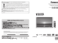 1
1
-
 2
2
-
 3
3
-
 4
4
-
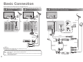 5
5
-
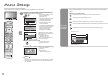 6
6
-
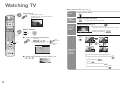 7
7
-
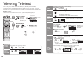 8
8
-
 9
9
-
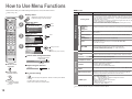 10
10
-
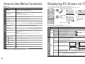 11
11
-
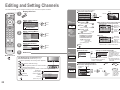 12
12
-
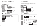 13
13
-
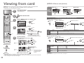 14
14
-
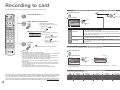 15
15
-
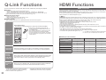 16
16
-
 17
17
-
 18
18
-
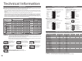 19
19
-
 20
20
-
 21
21
-
 22
22


Panasonic TH42PV600EY Owner's manual
- Category
- LCD TVs
- Type
- Owner's manual
- This manual is also suitable for
Ask a question and I''ll find the answer in the document
Finding information in a document is now easier with AI
Related papers
-
Panasonic TH37PV60EY Operating instructions
-
-
-
-
-
-
Panasonic TH-37PV60E Owner's manual
-
Panasonic TH-42PV62EH Operating instructions
-
-
Other documents
-
Polaroid 20070918 User manual
-
Palsonic LCD TV COMBO User manual
-
Sanyo CE22LD90-B User manual
-
Audiovox FPE2706DV User manual
-
-
-
-
LG 42LH5700 User manual
-
Philips FlatTV Matchline 50FD9955 Owner's manual
-
Sanyo CE32FWN6-B User manual