Page is loading ...

Read these instructions carefully. These
instructions MUST stay with this product.
USA
SERVICE OFFICE
Dometic Corporation
1120 North Main Street
Elkhart, IN 46514
SERVICE CENTER &
DEALER LOCATIONS
Please Visit:
www.eDometic.com
This Unit is designed for OEM installation. All initial installations must be approved by Dometic Corporation.
RECORD THIS INFORMATION FOR FUTURE
REFERENCE:
Model Number
Serial Number
ADB Model Number
ADB Serial Number
Date Purchased
REVISION C
Form No. 3316201.000 6/18
(French 3316202.000_C)
©2018 Dometic Corporation
LaGrange, IN 46761
Roof Top Unit (Quiet Zone Ducted Application)
Description Blizzard NXT
TM
Model
Board Built In Thermostat Optional Indoor
Temperature
Sensor
Air Conditioner
CCC 2 Controls H541815A
H541816A
Board Built In 3314082.000 CCC 2-Blk
3314082.011 CCC 2-Wht
3311931.000-20′
3311931.012-40′
3311931.020-60′
LCD SZ Controls H541915A
H541916A
Board Built In 3313192.000 C/F-Wht
3313192.019 C/F-Blk
N/A
Heat Pump
CCC 2 Controls H551816A Board Built In 3314082.000 CCC 2-Blk
3314082.011 CCC 2-Wht
3311931.000-20′
3311931.012-40′
3311931.020-60′
LCD SZ Controls H551916A Board Built In 3313193.000 C/F/HP-Wht
3313193.017 C/F/HP-Blk
N/A
INSTALLATION
INSTRUCTIONS

2
TABLE OF CONTENTS
INTRODUCTION ..................................................................................................................................................................2
DOCUMENT SYMBOLS.......................................................................................................................................................2
IMPORTANT SAFETY INSTRUCTIONS ............................................................................................................................3
A. Recognize Safety Information ...................................................................................................................................3
B. Understand Signal Words ..........................................................................................................................................3
C. Supplemental Directives ............................................................................................................................................ 3
D. General Safety Messages .........................................................................................................................................3
SPECIFICATIONS ................................................................................................................................................................4
A. Table - Unit Data ........................................................................................................................................................4
B. Roof Requirements ....................................................................................................................................................4
C. Table - Air Distribution Duct Sizing & Design ............................................................................................................. 4
INSTALLATION INSTRUCTIONS .......................................................................................................................................5
A. Choosing Proper Location For Unit ...........................................................................................................................5
B. Roof Preparation .......................................................................................................................................................5
C. Air Distribution Duct Sizing & Design ........................................................................................................................6
D. Wiring Requirements .................................................................................................................................................8
E. Choosing Thermostat Location ..................................................................................................................................9
F. Thermostat, Optional Indoor Temperature Sensor & Thermostat Communication Cable Installation ......................9
G. Placing Unit On Roof ............................................................................................................................................... 11
H. (CCC2SystemOnly)Conguration ........................................................................................................................ 11
I. 120 Vac Power Supply Connection .........................................................................................................................12
J. LCD SZ System Low Voltage Wire Connections ..................................................................................................... 14
K. CCC 2 System Low Voltage Wire Connections .......................................................................................................14
L. Securing Unit To Roof ..............................................................................................................................................14
M. (LCD SZ System Only) System Checkout ............................................................................................................... 16
N. (CCC 2 System Only) Reset & Checkout ................................................................................................................16
O. (CCC2SystemOnly)Furnace/AquaTemperatureDierentialSetting ................................................................... 16
GENERAL INFORMATION ................................................................................................................................................17
A. Heat Gain ................................................................................................................................................................17
B. Condensation ..........................................................................................................................................................17
C. Air Distribution .........................................................................................................................................................17
WIRING DIAGRAMS ..........................................................................................................................................................18
A. Simple RV Wiring Diagram ...................................................................................................................................... 18
B. Unit Wiring Diagrams ...............................................................................................................................................19
DOCUMENT SYMBOLS
Indicates additional information that is NOT related
to physical injury.
Indicates step-by-step instructions.
INTRODUCTION
This air conditioner/heat pump (hereinafter referred to as “unit” or “product”) is designed and intended for installation on the
roof of a Recreational Vehicle (hereinafter referred to as RV) during the time it is manufactured.
Read these instructions and highlight the appropriate steps for your particular procedure before starting the installation.
This unit can be installed by one person with brief help from additional personnel. Use these instructions to ensure a properly
installed, and properly functioning product.
DometicCorporationreservestherighttomodifyappearancesandspecicationswithoutnotice.

3
IMPORTANT SAFETY INSTRUCTIONS
This manual has safety information and instructions to help
users eliminate or reduce the risk of accidents and injuries.
A. Recognize Safety Information
This is the safety alert symbol. It is used to
alert you to potential physical injury hazards.
Obey all safety messages that follow this
symbol to avoid possible injury or death.
B. Understand Signal Words
A signal word will identify safety messages and
property damage messages, and will indicate the
degree or level of hazard seriousness.
indicates a hazardous situation that,
if NOT avoided, could result in death or serious in-
jury.
indicates a hazardous situation that,
if NOT avoided, could result in minor or moderate
injury.
is used to address practices NOT
related to physical injury.
C. Supplemental Directives
Read and follow all safety information and
instructions to avoid possible injury or death.
Read and understand these instructions be-
fore [installing / using / servicing / performing
maintenance on] this product.
Incorrect [installation / operation / servicing /
maintaining] of this product can lead to seri-
ous injury. Follow all instructions.
The installation MUST comply with all ap-
plicable local or national codes, including
the latest edition of the following standards:
U.S.A.
● ANSI/NFPA70, National Electrical Code
(NEC)
● ANSI/NFPA 1192, Recreational Vehicles
Code
CANADA
● CSA C22.1, Parts l & ll, Canadian Electri-
cal Code
● CSA Z240 RV Series, Recreational
Vehicles
D. General Safety Messages
Failure to obey the following warn-
ings could result in death or serious injury:
● This product MUST be [installed / serviced] by a
qualiedservicetechnician.
● Do NOT modifythisproductinanyway.Modica-
tion can be extremely hazardous.
● Do NOT add any devices or accessories to this
product except those specically authorized in
writing by Dometic Corporation.

4
A. Table - Unit Data
Model No. Nominal
Capacity
(BTU HR)
Cooling
Electrical
Rating
Compressor
Rated Load
Amps
Compressor
Locked
Rotor
Amps
Fan Motor
Rated Load
Amps
Fan Motor
Locked
Rotor
Amps
Refrigerant
R-410A
(oz)
Minimum
Wire Size*
AC Circuit
Protection
***Installer
Supplied
Minimum
Generator
Size**
1 Unit / 2 Units
H541815A72X 13,500 120 Vac
60 Hz 1 ph
12.7 68.0 2.8 8.0 19.5 12 AWG
Copper
Up to 24'
20 Amp 3.5 kW / 5.0 kW
H541816A72X 15,000 13.2 70.0 2.8 8.0 20.1 20 Amp 3.5 kW / 5.0 kW
H541915A72X 13,500 12.7 68.0 2.8 8.0 19.5 20 Amp 3.5 kW / 5.0 kW
H541916A72X 15,000 13.2 70.0 2.8 8.0 20.1 20 Amp 3.5 kW / 5.0 kW
H551816A72X 15,000 13.2 70.0 2.8 8.0 21.0 20 Amp 3.5 kW / 5.0 kW
H551916A72X 15,000 13.2 70.0 2.8 8.0 21.0 20 Amp 3.5 kW / 5.0 kW
* For wire length over 24 ft., consult the National Electrical Code for proper sizing.
** Dometic Corporation gives GENERAL guidelines for generator requirements. These guidelines come from experiences
people have had in actual applications. When sizing the generator, the total power usage of your RV must be considered.
Keep in mind generators lose power at high altitudes and from lack of maintenance.
*** CIRCUIT PROTECTION: Time Delay Fuse or Circuit Breaker Required.
B. Roof Requirements
● A14-1/4″x14-1/4″(±1/8″)squareopening(hereinafterreferredtoas“roofopening”)isrequiredforinstallingthis
unit. This opening is part of the return air system of the unit and MUSTbenishedinaccordancewithNFPA1192.
● Roof construction with rafters/joists support frames on a minimum of 16 inch centers.
C. Table - Air Distribution Duct Sizing & Design
Duct Cross Sectional Area 21.0 Sq. In. Min.
Duct Size
Depth
Width
Total Duct Length
Duct Length (short run)
1-1/2 In. Min. - 2-1/2 In. Max.
7.0 In. Min. - 10.0 In. Max.
15.0 Ft. Min. - 40.0 Ft. Max.
1/3 Total Duct Length
Register Requirements per A/C Unit
Number Required
Supply Register Free Air Area
Return Register Free Air Area
Distance From Duct End
Distance From Elbow
4 Min. - 8 Max.
14.0 Sq. In.
40.0 Sq. In.
5.0 In. Min. - 8.0 In. Max.
15.0 In.
Total System Static Air Pressure
Blower at High Speed,
Filter & Grille In Place
0.55 - 1.10 In. W.C.
SPECIFICATIONS

5
A. Choosing Proper Location For Unit
Thisunitisspecicallydesignedforinstallationontheroof
of an RV. When determining your cooling requirements, the
following should be considered:
● Size of RV;
● Window area (increases heat gain);
● Amount of insulation in walls and roof;
● Geographical location where the RV will be
used;
● Personal comfort level required.
1. For one unit installation: The unit should be
mounted slightly forward of center (front to back)
and centered from side to side.
2. For two unit installations: Install one unit 1/3 and
one unit 2/3’s from front of RV and centered from
side to side.
Itispreferredthattheunitbeinstalledonarelativelyat
and level roof section measured with the RV parked on a
level surface. See table below for maximum acceptable tilt.
Model
Number
Max Tilt
(All Directions)
H541815A
H541816A
H541915A
H541916A
H551816A
H551916A
15°
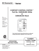
3. After Location Has Been Selected:
a. Check for obstructions in the area where unit
will be installed. See (FIG. 1).
FIG. 1
Dimensions Are Nominal
Keep These Air
Flow Areas Free
Of Obstructions
Front
Center Line Of Unit
Roof Opening
13-7/8″
40″
30″
4″
18″
4″
INSTALLATION INSTRUCTIONS
b. Maintain structural integrity.
Otherwise damage to product and/or RV
could occur.
The roof must be designed to support 130
pounds when RV is in motion. Normally
a 200 lb. static load design will meet this
requirement.
B. Roof Preparation
1. FIRE OR ELECTRICAL SHOCK
HAZARD. Make sure there are no obstacles
(wires, pipes, etc.) inside RV’s [roof / oor /
walls]. Shut OFF gas supply, disconnect 120
Vac power from RV, and disconnect positive (+)
12 Vdc terminal from supply battery BEFORE
drilling or cutting into RV. Failure to obey these
warnings could result in death or serious injury.
Opening Requirements - Before preparing
the ceiling opening, the type of system op-
tions MUST be decided upon. Read all of
the following instructions before beginning
the installation.
2. Carefully mark and cut the required roof opening.
See "B. Roof Requirements" on page (4).
3. Using the roof opening as a guide, cut the match-
ing hole in the ceiling.
4. Maintain structural integrity. Oth-
erwise damage to product and/or RV could oc-
cur.
NEVER create a low spot on RV
roof. Otherwise, water will pool and could cause
a leak.
The opening created must be framed to provide
adequate support and prevent air from being
drawn from theroof cavity. Framingstock 3/4″
or more in thickness must be used. Remember
to provide an entrance hole for power supplies,
indoor temperature sensor (if applicable), ther-
mostat communication cable, and furnace wires
(if applicable) at the front of the opening. See
(FIG. 2).

6
INSTALLATION INSTRUCTIONS
3/4″ Min.
Leave Access For
Power Supply Wiring
FIG. 2
15″ Min. At
Front Of
Opening
Do Not Cut Roof
Structure Or
Rafters
Good-Rafters
Supported By
Cross Beams
Good Location
Between Roof
Rafters
Frame Opening So It
Won't Collapse When
Bolting Down Unit
C. Air Distribution Duct Sizing & Design
The installer of this system must design the air distribution
system for their particular application. Several requirements
must be met for the unit to operate properly. These require-
ments are as follows:
1. Make sure ductwork will NOT
bend or collapse during and after installation,
and that it is correctly insulated and sealed.
Otherwise, damage to roof structure and ceiling
could occur.
2. All discharge air ducts must be properly insu-
lated to prevent condensation from forming on
their surfaces or adjacent surfaces during op-
eration of unit. This insulation must be R-7 mini-
mum. See (FIG. 3).
3. Ducts and their joints must be sealed to prevent
condensation from forming on adjacent surfaces
during operation of the unit.
4. Return air openings must have 40 square inches
minimumfreeareaincludingthelter.
5. Returnairtotheunitmustbelteredtoprevent
dirt accumulation on unit cooling surface.
Frame
DuctDuct
Frame
Frame
Roof Opening
Roof Opening
Roof
SIDE VIEW
(TOWARD BACK OF RV)
Duct
Ceiling
Duct
Insulation
TOP VIEW
(BACK OF RV)
FIG. 3
6. Air Distribution Installation
a. Dometic Corporation recommends the basic
congurations shown in (FIG. 4), (FIG. 5),
(FIG. 6), & (FIG. 7). We have found by test-
ing, that these congurations work best in
most applications. It is the responsibility of
theinstallertorevieweachRVoorplanto
determine the following:
● Duct size
● Duct layout
● Register size
● Register location
● Thermostat location
● Indoor Temperature Sensor Location
These items must be determined in conjunc-
tion with the Air Distribution Duct System
Sizing & Design requirements. See "C. Table
- Air Distribution Duct Sizing & Design" on
page (4).
Installer responsible for any necessary
adapters between unit and ductwork.

7
INSTALLATION INSTRUCTIONS
Return
Supply
Supply
Return
FIG. 4
Return
Supply
Return
Supply
FIG. 5
Return
Return
Supply
Supply
Supply
Supply
FIG. 6

8
D. Wiring Requirements
1. Route a copper, with ground, 120 Vac supply
wire from the time delay fuse or circuit breaker
box to the roof opening. Use a listed/certied
non metallic - sheathed single strand cable. See
"A. Table - Unit Data" on page (4).
a. This supply wire must be located in the front
portion of the roof opening.
b. The power MUST be on an appropriately
sized separate time delay fuse or circuit
breaker. See "A. Table - Unit Data" on page
(4).
c. Make sure that at least 15″ of supply wire
extends into the roof opening. This ensures
an easy connection at the junction box.
d. Protect the wire where it passes into the
opening with approved method.
2. Route a dedicated 12 Vdc supply wire (18-22)
AWG) from the RV converter (ltered side) or
battery to the roof opening.
When a Comfort Control Center 2 (here-
inafter referred to as CCC 2) thermostat
is being installed with more than 2 zones,
route a dedicated 12 Vdc supply wire
(18-22 AWG) to zone 1 and zone 3 roof
opening.
a. This supply wire must be located in the front
portion of the roof opening.
b. Make sure that at least 15″ of supply wire
extends into the roof opening.
3. Thermostat Communication Cable
a. CCC 2 Thermostat
I. Route a 4 conductor communication ca-
ble from the roof opening to the thermo-
stat mounting location using the shortest
most direct route. Make sure that at least
15″ofthewireextendsintotheroofopen-
ing and 6″ extends from the wall at the
thermostat mounting location. See "E.
Choosing Thermostat Location" on page
(9).
When more than one unit is being
installed (additional zones) with the
CCC 2 thermostat, an additional
4 conductor communication cable
MUST be routed to each additional
unit roof opening. Make sure that
atleast15″ofthewireextendsinto
the roof opening. See (FIG. 35).
b. LCD SZ Thermostat
I. Route a 3 conductor communication ca-
ble, 18 to 22 AWG, from the roof open-
ing to the Liquid Crystal Display Single
Zone (hereinafter referred to a LCD SZ)
thermostat mounting location. Make sure
thatatleast15″ofthewireextendsinto
theroofopeningand6″extendsfromthe
wall at the thermostat mounting location.
See "E. Choosing Thermostat Location"
on page (9).
4. (CCC 2 system only) Optional Indoor Tempera-
ture Sensor
INSTALLATION INSTRUCTIONS
Return
Return
Return
Return
Supply
Supply
FIG. 7

9
F. Thermostat, Optional Indoor
Temperature Sensor & Thermostat
Communication Cable Installation
1. CCC 2 System
a. The previously run communication cable (4
conductor telephone cable) must be termi-
nated with two (2) RJ-11-6C4P telephone
connectors. Refer to the crimp tool manufac-
turer for crimping instructions. See (FIG. 8)
& (FIG. 9).
RJ-11-6C4P connectors MUST be in-
stalled as shown in (FIG. 8) & (FIG. 9).
FIG. 8
FIG. 9
Flat 4-Conductor
Communication Cable
RJ-11-6C4P
Connector
Pin 1
Black
Red
Green
Yellow
b. Route the communication cable through the
2" diameter hole in the wall required for the
thermostat. See (FIG. 10).
c. Optional Indoor Temperature Sensor
I. Refer to the instructions provided with the
indoor temperature sensor for details of
installation.
a. Route an indoor temperature sensor (option-
al) from the roof opening to the indoor tem-
perature sensor location. The 2 pin connec-
tor end goes to the roof opening. See indoor
temperature sensor installation instructions
for proper sensor location.
5. If system includes a gas furnace, route two 18
gauge thermostat wires from the furnace to the
roof opening of the unit that will control it. If more
than one furnace is to be used, route the second
set of thermostat wires to the second unit. Make
sure that at least 15″ of wire extends into the
opening.
6. (CCC 2 system only) If an Energy Management
System (load shed feature) is to be used with
the control, two wires must be routed to the
roof opening of the zone to be managed. The
signal required for this function is normally an
open relay contact. When the EMS calls for the
compressortoshuto,therelaycontactsshould
close. Make sure that at least 15″ ofthe EMS
wire extends into the roof opening.
7. (CCC 2 system only) If an Automatic Generator
Start (AGS) kit will be installed, an additional 4
conductor communication cable must be routed
from the last unit to the location of the AGS kit.
Follow AGS kit instructions for installation.
E. Choosing Thermostat Location
1. CCC 2 system without an optional indoor tem-
perature sensor and LCD SZ system
a. The proper location of the thermostat is very
important to ensure that it will provide a com-
fortable RV temperature. Observe the follow-
ing rules when selecting a location.
● Locatethethermostat54″abovetheoor.
● Install the thermostat on a partition, not
on an outside wall.
● NEVER expose the thermostat to direct
heat from lamps, sun, or other heat pro-
ducing items.
● Avoid locations close to doors that lead
outside, windows, or adjoining outside
walls.
● Avoid locations close to supply registers
and the air from them.
2. CCC 2 system with an optional indoor tempera-
ture sensor in ALL zones
a. The thermostat may be mounted anywhere
in the RV that is convenient. Try to avoid
hard to reach and hard to see areas.
I. Refer to the instructions provided with the
indoor temperature sensor for details of
installation.
INSTALLATION INSTRUCTIONS

10
INSTALLATION INSTRUCTIONS
FIG. 10
CCC 2 Thermostat
(Rear View)
Wall
2" Diameter
Communication Cable
d. Thermostat Installation
I. Carefully separate the thermostat base
plate from the thermostat cover. Insert a
small screw driver into the slot on bottom
of thermostat and disengage the tab. See
(FIG. 11).
FIG. 11
Disengage Tab
CCC 2 Thermostat
II. Insert the 4 conductor communication ca-
ble through the hole in base plate. Align
thermostat base plate with hole in wall.
Make sure base plate is level and attach
base plate to wall using the four (4) sup-
plied screws.
III. Insert the 4 conductor communication
cable connector (RJ-11-6C4P) into the
connector on the back of the thermostat.
See (FIG. 12).
IV. Align the thermostat with the back plate
and snap into position.
FIG. 12
4 Conductor
Communication Cable
2. LCD SZ System
Wire colors listed for the communication
cable (3 conductor cable) match the wire
colors in the unit wire harness and the wire
harness at the LCD SZ electronic control
box. Available wire colors may vary.
a. Remove the cover from the LCD SZ thermo-
stat. Depress tab on bottom of thermostat
and separate it from the base.
b. Insert the previously run communication ca-
ble (3 conductor cable) through the hole in
the base assembly.
c. Cut back the outer cable shield approxi-
mately3inchesandstrip1/4″insulationfrom
each wire.
d. Mount the thermostat level on the wall using
the screws provided.
e. Make the following connections to the ther-
mostat. See (FIG. 13).
FIG. 13
12-
COMMS
12+
● Red/white wire to the 12V+ terminal
● Black wire to the 12V– terminal
● Orange wire to the "COMMS" terminal

11
f. Inspect all connections to make sure they
are tight and not touching any other termi-
nals or wires.
g. Push the wires back through the base into
the wall. Place cover on the thermostat and
push until an audible click is heard.
G. Placing Unit On Roof
1. Remove the unit from the carton and discard
carton.
2. LIFTING HAZARD. Use proper
lifting technique and control when lifting product.
Failure to obey this caution could result in injury.
3. Identify foam blocks and roof gasket as shown.
Ensure they are properly located. See (FIG. 14).
FIG. 14
Roof Gasket
Foam
Blocks
Foam
Blocks
4. Place unit on roof.
5. Do NOT slide unit. Otherwise,
damage to gasket (on bottom of unit) may occur,
and could cause a leak. See (FIG. 15).
FIG. 15
Do Not Slide
6. Position unit to the side of the roof opening to
access wiring.
H. (CCC 2 System Only) Conguration
1. ElectronicControlConguration
Depending on the equipment options installed
by the RV manufacturer, the appropriate dip
switches will need to be switched to the "ON"
position. Placing the switch in the "ON" position
selects that option. See (FIG. 16), (FIG. 17), &
(FIG. 18).
FIG. 16
Dip Switches
Dip switches are in the "OFF" position
when shipped from the factory except
heat pump and factory installed heat strip
models. On these models the appropriate
dip switch, heat pump or heat strip, is in
the "ON" position from the factory.
To gain access to the dip switches, the
outside plastic shroud MUST be removed
from the unit. Next remove the electrical
box cover. The electrical box will be on the
curb side of the RV after installation. See
(FIG. 16).
FIG. 17
Dip Switches
Zone 2
Ext. Stage
Zone 3
Zone 4
Stage
Heat Strip
Heat Pump
Furnace
Dehumidify
Gen Start
INSTALLATION INSTRUCTIONS

12
a. Ext. Stage - Ext. Stage is not used on this
unit. Leave in the "OFF" position.
b. Zone selection - Each CCC 2 thermostat can
have up to 4 zones. When only one unit is in-
stalled it becomes Zone 1 and no dip switch
setting is required. Each additional unit must
be assigned a zone (2 through 4). Each unit
musthaveadierentzonesetting.
c. Stage selection - Stage is not used on this
unit. Leave in the "OFF" position.
d. Heat Strip - On heat strip models the #6
dip switch is in the "ON" position from the
factory. Non heat strip models leave in the
"OFF" position.
e. Heat Pump - On heat pump models the #7
dip switch is in the "ON" position from the
factory. Non heat pump models leave in the
"OFF" position.
f. Furnace - If a Furnace/Aqua heat system
has been connected to this unit, the fur-
nace dip switch must be placed in the "ON"
position.
g. Dehumidify - Dehumidify is not used on this
unit. Leave in the "OFF" position.
h. Gen Start selection - Leave in the "OFF"
position.
i. Install unit electrical box cover and out side
plastic shroud.
j. Repeat this procedure for each additional
zone.
FIG. 18
On Position
O Position
I. 120 Vac Power Supply Connection
1. ELECTRICAL SHOCK HAZARD.
Make sure 120 Vac power is disconnected from
RV. Failure to obey this warning could result in
death or serious injury.
2. ELECTRICAL SHOCK HAZARD.
Provide grounding in compliance with all appli-
cable electrical codes. Failure to obey this warn-
ing could result in death or serious injury.
3. Reach up into the return air opening of the unit
and pull down the unit electrical cord and power
supply wires. Note the included strain relief at-
tached to the electrical cord. See (FIG. 19).
FIG. 19
Low Voltage Wires
AC Power
Supply
Electrical
Cord
Strain Relief
Included
4. Remove the strain relief from its packaging and
set aside momentarily.
5. Carefully strip and prepare 120 Vac supply wire.
See (FIG. 20), (FIG. 21), (FIG. 22), (FIG. 23), &
(FIG. 24).
FIG. 20
Strip Jacket To 1″
FIG. 21
Hand Bend White
And Black Wires
Outward 90°
INSTALLATION INSTRUCTIONS

13
FIG. 22
Use Tip Of Pliers To Hold Wire In Place
While Hand Bending Wire At 90°
FIG. 23
Repeat With
Other Wire
FIG. 24
Trim Ground Wire To Length Of Outer Wires
6. Hold the clear strain relief cover with the bottom
facing upward. See (FIG. 25).
FIG. 25
Load Cable into Strain Relief
Wire Locator
Slots
Position Black Wire
Into Locator Slot
Strain Relief Cover
(Bottom Facing Upward)
Strain
Relief
Fingers
Roll Cable Sheath Into
Integral Strain Relief
7. Lay wire into locator slots, making sure the black
wire is placed into the polarization slot. See
(FIG. 25).
8. Press the cable sheath into the integral strain
relief slot. See (FIG. 25). Trimming of ground
wire and possibly others will be necessary.
Wires must not extend beyond the locators. See
(FIG. 26).
FIG. 26
Housing Assembly
Hinge
Slots
Strain Relief Cover
Wires Trimmed And
Correctly Located
In Locator Stops
Hinge
Posts
9. While holding the strain relief cover, position
the housing's hinge posts into the hinge slots
and press down until both lock into place. See
(FIG. 26).
10. Close the strain relief cover and housing by
hand. Squeeze the top and bottom closed with
tongue and groove pliers. See (FIG. 27). Pliers
mustbeaminimumof10″long.Squeezermly
on both sides, squarely across the connector
between ribs A and B to ensure wires seat com-
pletely into slots.
FIG. 27
Attaching Housing Assembly To Strain
Relief Cover With Tongue And Groove
Pliers, Squeeze Squarely & firmly
Between Ribs A & B
Strain Relief Cover 10″ Minimum
Rib A
Locking
Ramp
Locking
Latch
Rib B
Housing Assembly
INSTALLATION INSTRUCTIONS

14
11. Inspect the connector to ensure the wires have
been properly engaged into the housing assem-
bly contacts. A properly terminated wire is fully
seated into its proper slots with no signicant
bow of the cover. If the wires extend past the
insulation stops the wires must be re-terminated
with a NEW CONNECTOR. Once the cover has
been closed the connector cannot be re-used.
Failure to comply with this procedure may result
in the failure of the connector.
12. Mating and un-mating the completed connector
is illustrated below. See (FIG. 28).
FIG. 28
Housing
Assembly
Strain Relief
Cover
Depress Mating Latch
To Disconnect
To release the connector system, depress both mating
latches at the same time and pull the connectors apart.
To reconnect, simply re-mate the connectors and slide
them together until mating latches lock.
Strain Relief
Cover
Depress Mating
Latch To Disconnect
Housing
Assembly
"Hermaphroditic" Part Mates With Itself
J. LCD SZ System Low Voltage Wire
Connections
Make sure the positive (+) 12 Vdc
terminal is disconnected from supply battery. Oth-
erwise, damage to unit could occur.
1. Connect the previously run +12 Vdc supply wire
to the red wire protruding from the roof opening.
2. Connect the previously run –12 Vdc supply wire
to both the black wire protruding from the roof
opening and to the wire of the three wire cable
that goes to the thermostat 12V– terminal.
3. Connect the previously run furnace thermostat
wires (if applicable) to the blue wires protruding
fromtheroofopeningusingthesupplied1/4″in-
sulated connectors. The polarity of this connec-
tion does not matter.
4. Connect the red/white wire protruding from the
roof opening to the wire of the three wire cable
that goes to the thermostat 12V+ terminal.
5. Connect the orange wire protruding from the
roof opening to the wire of the three wire cable
that goes to the thermostat COMMS terminal.
K. CCC 2 System Low Voltage Wire
Connections
Make sure the positive (+) 12 Vdc
terminal is disconnected from supply battery. Oth-
erwise, damage to unit could occur.
1. Connect the previously run 12 Vdc supply wires
to the red and black wires protruding from the
roof opening. Connect +12 Vdc to the red wire;
–12 Vdc to the black wire.
2. Connect the previously run furnace thermostat
wires (if applicable) to the blue wires protruding
from the roof opening. The polarity of this con-
nection does not matter.
3. Terminate the 4 conductor communication
cable(s) protruding from the roof opening. The
cable(s) must be terminated with a telephone
RJ-11-6C4P connector. Refer to the crimp tool
manufacturer for crimping instructions.
RJ-11-6C4P connectors MUST be in-
stalled as shown in (FIG. 8) & (FIG. 9).
4. Plug the 4 conductor communication cable into
one of the couplers protruding from the roof
opening. If more than one zone is used, the sec-
ond coupler is used to join each additional zone.
5. Plug the indoor temperature sensor cable (if ap-
plicable) into the 2 pin matching connector pro-
truding from the roof opening.
6. Connect the previously run Energy Management
System wires (if applicable) to the yellow wires
protruding from the roof opening. The polarity of
this connection does not matter.
7. If an automatic generator start (AGS) kit is in-
stalled, follow installation instructions furnished
with AGS kit.
L. Securing Unit To Roof
LIFTING HAZARD. Use proper lift-
ing technique and control when lifting product. Fail-
ure to obey this caution could result in injury.
Do NOT slide unit. Otherwise, dam-
age to gasket (on bottom of unit) may occur, and
could cause a leak.
1. Lift and place the unit over the prepared open-
ing using the gasket on the unit as a guide. See
(FIG. 29).
INSTALLATION INSTRUCTIONS

15
FIG. 29
Do Not Slide
Lift And Place
Front
Unit May Vary In Appearance
Model
H540315
H540316
Shown
2. Remove shroud.
3. Align four (4) Dometic cubes with base pan as
shown. See (FIG. 30).
Dometic cubes ensure proper foam block
compressionofapproximately1-1/6″.
Dometic
Cube
(X 4)
FIG. 30
Front
4. Maintaining alignment, place Dometic cubes be-
neath edge of base pan. See (FIG. 30), (FIG. 31)
& (FIG. 32).
FIG. 31
Front
Dometic Cubes
FIG. 32
Front
Dometic Cubes
5. Locate mounting holes in base pan.
6. Pre-drill the mounting holes in roof with 15/64"
bit with a drill gun using a depth gauge.
Do NOT drill without depth gauge to en-
sure bit does NOT penetrate cold air duct.
7. Match3″lagwithbondedsealingwasher.
8. Drivescrewusing9/16″socket.Finishinstalla-
tion with socket until base pan is lightly seated
on Dometic cubes. See (FIG. 30).
Tighten mounting bolts to achieve
proper foam block compression. Overtightening
could damage unit’s base pan. Under tighten-
ing will allow an inadequate roof seal, and could
cause a leak.
Proper compression is achieved when
foam blocks compress to approximately
1-1/6″ so that Dometic cubes no longer
move freely beneath the base pan. There
should be slight resistance between Do-
metic cubes and base pan upon attempt-
ed removal of cubes.
FIG. 33
Dimensions Are Nominal
1-1/6″
INSTALLATION INSTRUCTIONS

16
O. (CCC 2 System Only) Furnace/Aqua
Temperature Dierential Setting
Thissystemcanbeconguredtooperateusingan
ON//OFFdierentialofeither1degreeFor2de-
gree F. See (FIG. 34).
1. To set the dierential, simultaneously press
the PROGRAM button and the up button
on the CCC 2 thermostat. “diF1” will appear in
the display while the buttons are pressed. See
(FIG.34).Tosetthe2degreedierential,simul-
taneously press the PROGRAM button and the
down button “diF2” will appear in the display
while the buttons are pressed.
FIG. 34
9. Remove Dometic cubes.
Save Dometic cubes for future unit instal-
lations.
10. Reinstall shroud.
M. (LCD SZ System Only) System Checkout
1. Verify that all features of the system work. See
the LCD SZ thermostat Operating Instructions or
User's Guide. Reconnect the 12 Vdc and 120
Vac power supplies. Check fan speeds, cooling
mode, heating mode, and furnace mode (if con-
nected) operation.
If features do not work, disconnect the 120 Vac
and 12 Vdc power supplies and verify that all
wiring is correct.
N. (CCC 2 System Only) Reset & Checkout
1. System Reset
After setting the dip switches in the electronic
control, do a system reset.
a. Re-connect the 12 Vdc and 120 Vac power
supplies.
b. Make sure the CCC 2 thermostat is in the
OFF mode.
c. Simultaneously press the MODE and ZONE
buttons. The LCD will display "IniT" and all
available zones.
d. Release the MODE and ZONE buttons.
e. Press the ON/OFF button to exit system set
up.
f. When a dip switch is turned on after initial
conguration,asystemresetwillneedtobe
done before the CCC 2 thermostat will rec-
ognize the updated selection.
2. System Checkout
a. Verify that all features of the installed sys-
tem work. See CCC 2 thermostat Operating
Instructions or User's Guide. Check the fan
mode, cooling mode, heating mode (if appli-
cable), and furnace mode (if applicable) op-
eration. If features do not work, disconnect
the 120 Vac and 12 Vdc power supplies and
verify that all wiring is correct and that the
correct dip switches have been set to the
"ON" position.
INSTALLATION INSTRUCTIONS

17
GENERAL INFORMATION
A. Heat Gain
The ability of this air conditioner to maintain the desired
inside temperature depends on the heat gain of the RV.
Some preventative measures taken by the occupants of
the RV can reduce the heat gain and improve the perfor-
mance of the air conditioner. During extremely high outdoor
temperatures, the heat gain of the RV may be reduced by:
1. Parking the RV in a shaded area
2. Using window shades (blinds and/or curtains)
3. Keeping windows and doors shut or minimizing
usage
4. Avoiding the use of heat producing appliances
Operation on High Fan/Cooling mode will give optimum
or maximum eciency in high humidity or high outside
temperatures.
Starting the air conditioner early in the morning and giving
it a “head start” on the expected high outdoor ambient will
greatly improve its ability to maintain the desired indoor
temperature.
For a more permanent solution to high heat gain, acces-
sories like Dometic outdoor patio and window awnings will
reduce heat gain by removing the direct sun. They also add
a nice area to enjoy company during the cool of the evening.
B. Condensation
The manufacturer of this unit will not be responsible for
damage caused by condensation forming on ceilings,
windows, or other surfaces. Air contains water vapor which
condenses when temperature of a surface is below Dew
point. During normal operation this unit is designed to
remove a certain amount of moisture from the air, depend-
ing on the size of the space being conditioned. Keeping
doors and windows closed when this air conditioner is in
operation will greatly reduce the chance of condensation
forming on interior surfaces.
C. Air Distribution
Each A/C unit operating in cool mode, must have a mini-
mum of 2 distribution vents, or the quick cool vent and one
vent open, to avoid the risk of freezing coils and improper
function.

18
A. Simple RV Wiring Diagram
(OPTIONAL)
12 VDC INPUT
2 WIRES
12 VDC INPUT
2 WIRES
FIG. 35
WIRING DIAGRAMS

19
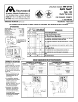
3. H551816A Wiring Diagram
WHT
COM
CAP
SENSOR
OUTDOOR
TEMP
BLK
BLK
REVERSING VALVE
A/C POWER MODULE BOARD
SENSOR
TEMP
INDOOR
GRN/YEL
FURNACE
LOAD SHED
FURNACE
LOAD SHED
12V +
12V -
BLK
START
RED
PTCR
RED
(OPT)
FAN
BRN
PASSED
HERM
WHT
C
GRN/YEL
GRN/YEL
RED
MOTOR
WHT
WHT
O.L.
R
C
S
BLK
BLU
BLK
FIELD WIRING
FACTORY WIRING
BLK
YEL
FREEZE
SENSOR
RJ-11 CABLE
TO T-STAT
3312453.032
ONLY
CONDUCTORS
115 VAC
60 Hz, 1ɸ
USE COPPER
DIELECTRIC
COMPRESSOR
WHT
RED
T2 T3
T5
BLK
COM
K2
NO
RELAY
T4
BLK
RED
BLU
YEL
P6
BLU
T7
T6
P5 P4 P3
YEL
NO
T1
RELAY
P1
6
5
4
2
3
1
P2
K1
FIG. 38
4. H551916A Wiring Diagram
K1 RELAY
BLK
3313503.025
PTCR
(OPT)
RED
OL
C
R
S
YL
J4
OUTDOOR
TEMP
SENSOR
}
SOLAR OR
DIRTY FILTER
INDICATOR
IF USED
MOTOR
NO
COM
Y8
Y5
Y10
BLU
BLK
RED
Y9
FREEZE
SENSOR
J5
115 VAC,
USE COPPER
60 HZ, 1
ɸ
CONDUCTORS
ONLY
GRN/YEL (EARTH)
WHT (NEUT)
BLK (LINE)
TSTAT)
(TO
12V +
BLU/WHT
BLU/WHT
Y3
Y4
1
2
4
3
12V -
COMM
ORG
BLK
RED
RED/WHT
12V +
FURNACE
FURNACE
+
-
}
12V
SUPPLY
TSTAT
TO
J2
FACTORY WIRING
FIELD WIRING
PASSED DIELECTRIC
REVERSING VALVE
BR
WHT
WHT
BR
START
CAP
RED
WHT
BLK
BLU
FIG. 39
B. Unit Wiring Diagrams
1. H541815A & H541816A Wiring Diagram
P2
1
3
2
4
5
6
P1
RELAY
T1
NO
YEL
P3P4P5
T6
T7
BLU
P6
YEL
BLU
RED
BLK
T4
RELAY
NO
K2
COM
BLK
K1
T5
T3
RED
WHT
COMPRESSOR
DIELECTRIC
USE COPPER
60 Hz, 1ɸ
115 VAC
CONDUCTORS
ONLY
3312441.045
TO T-STAT
RJ-11 CABLE
SENSOR
FREEZE
YEL
BLK
FACTORY WIRING
FIELD WIRING
BLK
BLU
WHT
BLK
S
C
R
O.L.
WHT
WHT
MOTOR
RED
GRN/YEL
GRN/YEL
C
WHT
HERM
PASSED
BRN
FAN
(OPT)
RED
PTCR
RED
START
BLK
12V -
12V +
LOAD SHED
FURNACE
LOAD SHED
FURNACE
GRN/YEL
INDOOR
TEMP
SENSOR
A/C POWER MODULE BOARD
TEMP
OUTDOOR
SENSOR
CAP
MODELS
ON SOME
NOT USED
BLK
HEATER ELEMENT
GRY
LIMIT SWITCH
WHT
T2
COM
FIG. 36
2. H541915A & H541916A Wiring Diagram
COM
3313500.021
PTCR
(OPT)
BR
WHT
WHT
BR
START
CAP
RED
WHT
BLU
RED
OL
C
R
S
YL
}
SOLAR OR
DIRTY FILTER
INDICATOR
IF USED
MOTOR
NO
Y8
Y5
Y10
BLU
BLK
RED
Y9
FREEZE
SENSOR
J5
115 VAC,
USE COPPER
60 HZ, 1
ɸ
CONDUCTORS
ONLY
GRN/YEL (EARTH)
WHT (NEUT)
BLK (LINE)
TSTAT)
(TO
12V +
BLU
BLU
Y3
Y4
1
2
4
3
12V -
COMM
ORG
BLK
RED
RED/WHT
12V +
FURNACE
FURNACE
+
-
}
12V
SUPPLY
TSTAT
TO
J2
FACTORY WIRING
FIELD WIRING
BLK
PASSED DIELECTRIC
K1 RELAY
FIG. 37
WIRING DIAGRAMS
/