
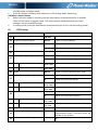
ENGLISH
Quick Guide
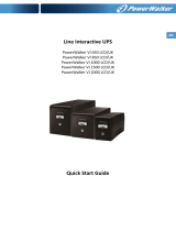
PowerWalker VFI RMG PF1 Series
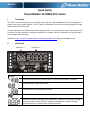
I. Assembly
The UPS can be assembled in a rack form using rack ears (Rack Mount Kit is not included) or in
tower form using tower holder. The LCD part can be taken out and turned 90 degrees to align
with orientation of the UPS.
Internal batteries are disconnected for transportation. It is necessary to open front panel and
connect the two available connectors before first usage. External batteries are connected in
front using third connector.
Details at https://support.powerwalker.com/kb/faq.php?id=83 (faq.powerwalker.com)
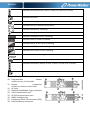
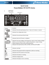
II. LCD Panel
Display
Function
Indicates the estimated backup time. H: hours, M: minute, S: second.
Indicates the configuration items
Indicates the warning and fault codes
Indicates that the UPS alarm is disabled.
Indicates the input voltage, input frequency, input current, battery voltage,
battery current, battery Power, ambient temperature, output voltage,
output frequency, load current and load percent.
Parameter 1
Parameter 2

ENGLISH
Indicates the load level by 0-24%, 25-49%, 50-74% and 75-100%.
Indicates overload.
Indicates that programmable management outlets are working.
Indicates the UPS connects to the mains.
Indicates the battery is working.
Indicates charging status
Indicates the bypass circuit is working.
Indicates the ECO mode is enabled.
Indicates the AC to DC circuit is working.
Indicates the PFC circuit is working.
Indicates the inverter circuit is working.
Indicates the UPS is working in converter mode.
Indicates the output is working.
Indicates the battery level by 0-24%, 25-49%, 50-74%, and 75-100%.
Indicates low battery.
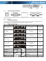
III. Rear panel view
10. Programmable outlets:
connect to non-critical loads.
11. Output receptacles:
connect to mission-critical loads.
12. AC input
13. Network/Fax/Modem surge protection
14. USB communication port
15. RS-232 communication port
16. SNMP intelligent slot
17. Emergency Power Off connector (EPO)
18. External battery connection
1
1000-1500 VA
2000 VA

ENGLISH
3000 VA
IV. Communication connection
USB port
RS-232 port
Intelligent slot
Network Surge Protection
Apart from standard USB Port, the UPS is equipped with RS-232. Those two ports do not work
at the same time.
V. Battery Replacement
The series offers hot-swappable battery sets easily accessible from front. The battery set can
be disconnected and replaced without changing any settings in the UPS.
VI. Modes and warnings
Warning
Icon
Alarm
Muted
Online mode
No Alarm
N/A
ECO mode
No Alarm
N/A
Frequency Converter
mode
No Alarm
N/A
Battery mode
Sounding every 5 seconds
Yes
Bypass mode
Sounding every 10
seconds
Yes
Standby mode
No Alarm
N/A
Low Battery
Sounding every 2 seconds
No
Overload
Sounding every second
No
Over input current
Sounding 2 beep every 10
seconds
No
Battery is not
Sounding every 2 seconds
No

ENGLISH
connected
Over Charge
Sounding every 2 seconds
No
Site wiring fault
Sounding every 2 seconds
No
EPO enable
Sounding every 2 seconds
No
Over temperature
Sounding every 2 seconds
No
Charger failure
Sounding every 2 seconds
No
Battery fault
Sounding every 2 seconds
(At this time, UPS is off to
remind users something
wrong with battery)
No
Out of bypass voltage
range
Sounding every 2 seconds
No
Bypass frequency
unstable
Sounding every 2 seconds
No
Battery replacement
Sounding every 2 seconds
No
EEPROM error
Sounding every 2 seconds
No
VII. Frequency Converter Mode
When input frequency is within 40 Hz to 70 Hz, the UPS can be set at a constant output
frequency, 50 Hz or 60 Hz. The UPS will still charge battery under this mode. Frequency
Converter requires de-rating of the UPS Power to 80%.
VIII. Button operation
ON/Mute Button
Press and hold ON/Mute button for at least 2 seconds to turn on the UPS.
When the UPS is on battery mode, press and hold this button for at least 3 seconds to
disable or enable the alarm system. But it’s not applied to the situations when warnings
or errors occur.
Press this button to display previous selection in UPS setting mode (up key)
Press and hold ON/Mute button for 3 seconds to enter UPS self-testing while in AC
mode, ECO mode, or converter mode.
OFF/Enter Button
Press and hold this button at least 2 seconds to turn off the UPS. UPS will be in standby
mode under power normal or transfer to Bypass mode if the Bypass enable setting by
pressing this button.
Press this button to confirm selection in UPS setting mode.
Select Button
Press this button to change the LCD message for input voltage, input frequency, battery
voltage, output voltage and output frequency. It will return back to default display when
pausing for 10 seconds.
Press and hold this button for 3 seconds to enter UPS setting mode when UPS is in

ENGLISH
standby mode or bypass mode.
Press this button to display next selection in UPS setting mode. (down key)
ON/Mute + Select Button
When the main power is normal, press the two buttons simultaneously for 3 seconds.
Then UPS will enter to bypass mode. This action will be ineffective when the input
voltage is out of acceptable range.
In setting mode, press the two buttons simultaneously for 0.2s to exit the setting mode.
IX. UPS Setting
Parameter 1
Parameter 2
01
Output voltage setting
200/208/220
/230/240
Value in V AC
02
Frequency Converter Mode
ENA/dIS
Enable or Disable (default)
03
Output frequency setting
50 / 60
Value in Hz
50 / 60
Value in Hz
04
ECO Mode
ENA/dIS
Enable or Disable (default)
05
ECO voltage range setting
HLS
Upper Limit for Input Voltage
LLS
Bottom Limit for Input Voltage
HS
Upper Limit for Input Voltage
Nominal
+7V to +24V
Value in V AC
LS
Bottom Limit for Input Voltage
Nominal
-7V to -24V
Value in V AC
06
Bypass
ENA/diS
Enable or Disable (default) bypass mode
07
Bypass Input Voltage setting
HLS
Upper Limit for Input Voltage
LLS
Bottom Limit for Input Voltage
HS
Upper Limit for Input Voltage
Nominal
+7V to +24V
Value in V AC
LS
Bottom Limit for Input Voltage
Nominal
-7V to -24V
Value in V AC
08
Bypass frequency range setting
HLS
Upper Limit for Input Frequency
LLS
Bottom Limit for Input Frequency
HS
Upper Limit for Input Voltage
Nominal
+1 to +5 Hz
Value in Hz
LS
Bottom Limit for Input Voltage
Nominal
-1 to -5 Hz
Value in Hz
09
Programmable outlets
ENA/dIS
Enable or Disable (default)
10
Programmable outlets setting
0-999
Backup time limit in minutes for
programmable outlets. 0 actually means 10s
and 999 means disabled
11
Autonomy limitation setting
0-999/dIS
Backup time limit in minutes. 0 actually means
10s

ENGLISH
12
Battery total AH setting
7-999
Total Power of batteries in Ah (2 strings of 9Ah
means 18Ah regardless of the length of the
string)
13
Maximum charger current setting
1 / 2 / 4 / 6 /
8 / 10 / 12
Total Power of batteries in Ah (2 strings of 9Ah
means 18Ah regardless of the length of the
string)
14
Charger boost voltage setting
2.25-2.40V
Boost Charging voltage per cell. Each battery
has 6 cells.Default is 2.36V/cell means
14.16V/bat
15
Charger float voltage setting
2.20-2.33V
Float Charging voltage per cell. Each battery
has 6 cells.Default is 2.28V/cell means
13.68V/bat
16
EPO logic setting
AO
Active Open (default). EPO will be activated if
pins 1 and 2 are not shorted
AC
Active Close. EPO will be activated if pins 1 and
2 are shorted
17
External output isolation transformer
connection
ENA/dIS
Allow or disallow (default) external output
isolation transformer connection.
18
Display setting for autonomy time
EAT/RAT
EAT will display the remaining autonomy time
(Default). RAT will show accumulated
autonomy time.
19
Acceptable input voltage range setting
HLS
Upper Limit for Input Voltage
LLS
Bottom Limit for Input Voltage
HS
Upper Limit for Input Voltage
280 / 290 /
300
Value in V AC
LS
Bottom Limit for Input Voltage
110 / 120 /
130 / 140 /
150 / 160
Value in V AC
00
Exit Settings
Maximum charger current setting
Please set the appropriate charger current based on battery Power used. The recommended
charging current is 0.1C~0.3C of battery Power as following table for reference.
Charging current (A)
2
4
6
8
10
12
Battery Power(AH)
7-20Ah
20-40Ah
40-60Ah
60-80Ah
80-100Ah
100-150Ah
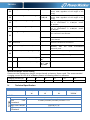
X. Technical Specification
MODEL
VFI 1000 RMG
VFI 1500 RMG
VFI 2000 RMG
VFI 3000 RMG
POWER*
1000VA/1000
W
1500VA/1500
W
2000VA/2000
W
3000VA /
3000W
INPUT
Voltage
Low Line Transfer
160VAC/140VAC/120VAC/110VAC ± 5 %
Low Line
Comeback
175VAC/155VAC/135VAC/125VAC ± 5 %
High Line Transfer
300 VAC ± 5 %
High Line
Comeback
290 VAC ± 5 %

ENGLISH
Frequency Range
40Hz ~ 70 Hz
Power Factor
≧ 0.99 @ full load
THDi
≦ 5% @ 205-245VAC
THDU < 1.6% @ input and full linear load condition
OUTPUT
Output voltage
200/208/220/230/240VAC
AC Voltage
Regulation
± 1% (Batt. Mode)
Frequency
Synchronized
Range
47 ~ 53 Hz or 57 ~ 63 Hz
Frequency Range
50 Hz ± 0.1 Hz or 60Hz ± 0.1 Hz (Batt. Mode)
Current Crest Ratio
3:1
Harmonic
Distortion
≦ 2 % THD (Linear Load) ; 4 % THD (Non-linear Load)
Transfer Time
Zero from AC Mode to Battery Mode
Below 4ms from Inverter to Bypass
Waveform
Pure Sinewave
EFFICIENCY
AC Mode
≧89% @ full charged battery
≧91% @ full charged battery
ECO Mode
≧96% @ full charged battery
Battery Mode
≧88%
≧90%
BATTERY
Battery Type
12V/7AH
12V/9AH
12V/7AH
12V/9AH
Numbers
3
6
Recharge Time
3 hours recover to 95% Power for internal battery@ 2A charging
current
Charging Current
Default 2A, max. 12A
adjustable
Default: 2A, Max: 8A adjustable
PHYSICAL
Dimension, D x W x
H
410 x 438 x 88
630 x 438 x 88
Net Weight (kgs)
14.1
15.5
23.3
27.5
ENVIRONMENT
Operation
Humidity
20-95 % RH @ 0- 40°C (non-condensing)
Noise Level
Less than 50dBA @ 1 Meter (With fan speed control)
MANAGEMENT
USB with HID
PowerWalker ViewPower
* Derate Power to 80% of Power when the output voltage is adjusted to 200VAC or 208VAC.
-
 1
1
-
 2
2
-
 3
3
-
 4
4
-
 5
5
-
 6
6
-
 7
7


PowerWalker VFI 1500 RMG PF1 Quick start guide
- Type
- Quick start guide
- This manual is also suitable for
Ask a question and I''ll find the answer in the document
Finding information in a document is now easier with AI
Related papers
-
 PowerWalker VFI 1500 CG PF1 UK Quick start guide
-
 PowerWalker VFI 1000 CRM LCD Uninterruptible Power Supply System User manual
-
PowerWalker VI CW Series User manual
-
 PowerWalker VFI 1500 LCD Owner's manual
-
PowerWalker VFI 2000 CRS Quick start guide
-
PowerWalker VFI 1000 C LCD Quick start guide
-
PowerWalker VFI 2000 AT FR Quick start guide
-
 PowerWalker VFI 2000C LCD Specification
-
PowerWalker VI 800 Owner's manual
-
PowerWalker VFI 10000 RMG Owner's manual


Other documents
-
Liebert GHT MT+ User manual
-
PROLINK Master II Series (1P/1P) User manual
-
 Power-all FRUK19-3000HV-01V User manual
-
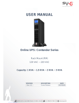 Sy-G Contender 1.5 KVA User manual
-
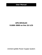 Orvaldi V1000 User manual
-
 Smartbitt 1.5K User manual
-
Vertiv Liebert® GXT MT+ 1000VA - 3000VA User manual
-
DirekTronik 20104114 Owner's manual
-
 BlueWalker PowerWalker VI 850 LCD/UK Specification
-
BlueWalker VFI 1000R LCD Specification


