Page is loading ...

Forum™
(IMA-240)
Classroom Audio System
Installation Manual

1
Welcome
Congratulations on the purchase of your new TeachLogic®
classroom audio system. You can be assured that this product
fulfills all specifications and was produced to high quality
control standards.
TeachLogic incorporates the latest state of the art technology,
employs the most advanced manufacturing methodology and
uses only premium quality components to assure many years
of reliable performance. We appreciate your confidence by
your selection of our product. It is TeachLogic’s intent to
uphold that confidence by providing factory assistance and
reseller support. This manual will help you learn to use and
gain the maximum benefit of the system.
We hope you will take the time to review
this manual to familiarize yourself with
the product operation and features.
TeachLogic, LLC
Longmont, Colorado USA
www.teachlogic.com

2
Safety Instructions
Read Instructions
All safety and operation instructions
should be read before operating this
TeachLogic product.
Retain Instructions
Safety and operating instructions should
be kept for future reference.
Water & Moisture
This product should not be operated near
water.
Heat Environment
Do not subject this product to excessive
heat conditions.
Power Source
This product must be connected to an AC
power source per the voltage input
specified and marked on the power
supply.
Do not insert any power cable not
provided by the manufacturer into the
product. Long prongs can penetrate
inside electrical components or current
charging conductors.
Certifications
TeachLogic systems are manufactured
using lead-free processes and are free
of materials harmful to the environment.
They conform to European RoHS
guidelines for consumer products.
Power Cord Caution
Power cable should be routed clear of foot
traffic and supported clear of kinking or
abrasion.
Object Protection
Locate the operating unit so it will not be
subjected to falling objects or water entry.
Do not drill hole in or screw objects into the
product except as specified by
manufacturer.
Internal Service
User should not attempt to service this
product. All internal service must be
accomplished by a qualified technician.
Electric Shock
Do not adapt or modify the AC power plug.
Do not remove thus lifting the earth ground
connection (3rd prong) or use power supply
without a connector to a 3-prong grounded
outlet.
CAUTION
Recycle—Do not dispose rechargeable batteries in
trash. It is unlawful to do so in numerous states. Go
Green. Save our resources and do not contaminate.
Contact: Earth911.com
1-800-CLEANUP

3
System info
Date of Purchase
Model Number
Serial Number
Notes
Contact
If you should encounter an
unresolved issue, please contact
the TeachLogic customer service
department for further assistance.
760-631-7800 | support@teachtogic.com | teachlogic.com
Limited warranty
For full warranty details refer to teachlogic.com/warranty.

4
Contents
System Overview .......................................................................................................................... 5
System Diagram ........................................................................................................................... 6
Installation ................................................................................................................................... 7
Installation Planning ...................................................................................................................... 7
Connection of Speakers ............................................................................................................. 8-9
Installation of Ceiling Sensor ...................................................................................................... 10
Integration ................................................................................................................................. 11
Computer Anti-Hum .................................................................................................................... 11
Video Conferencing Connection ................................................................................................. 12
Configuration ............................................................................................................................ 13
Final Setup .................................................................................................................................. 13
Power Button Lights | Standby Function ..................................................................................... 14
Troubleshooting .......................................................................................................................... 15
System Specifications ................................................................................................................. 16

Forum
™
System Overview
5
www.teachlogic.com | support@teachlogic.com | (760) 631-7800
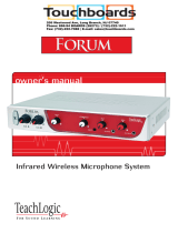
Front Panel
1. Power Button/ Indicator LED
2. Channel A Microphone Volume Control
3. Channel A Connectivity Indicator LED
4. Channel B Microphone Volume Control
5. Channel B Connectivity Indicator LED
6. DVD Input Volume Control
7. Computer Input Volume Control
8. Aux Input Volume Control
9. Aux Input Port (3.5 mm)
10. Line Output Volume Control
11. Line Output Port (3.5 mm)
(suitable for Lesson Capture)
Back Panel
1. Speaker Output
2. ALS Output (3.5 mm) & Gain Control
3. Three Band Equalizer Controls
4. Computer Input Port (3.5 mm) / Computer
Anti-Hum ON/OFF Switch
5. DVD Input Ports (Dual RCA, 0 dB)
6. Powered IR Ceiling Sensor Inputs (RCA x 2)
7. 5 Volt USB Output for chargers
8. Power Input: 19 VDC, 6.5 A
1
2
3
4
5
6
7
8
10
9
11
1
2
3
4
5
6
7
8


Forum
™
Installation Planning
7
www.teachlogic.com | support@teachlogic.com | (760) 631-7800
The goal of a classroom audio system is to evenly distribute sound throughout the listening area.
Component Placement
1. Amplifier: Choose location that
supports accessibility requirements and
wiring constraints for power, speakers,
ceiling sensor, and audio devices
connecting to the amplifier.
2. Ceiling Sensor: Locate in the center of
the ceiling; maintain line of sight to
teacher locations; keep away from
direct sunlight and electrical
interference.
3. Speakers: The Forum™ can power 4
classroom speakers. Mark location for
wall mount vs. ceiling mount and
confirm wiring run to the amplifier.
Ensure speakers evenly cover the
listening area.
4. Integrations/Connections: Confirm
location of other systems you plan to
connect to the amplifier such as audio
devices, computer, TV, projector, etc.,
noting how the wiring needs to run.
5. Charger: Confirm microphone charging
location for daily use/charging.

Forum
™
Speaker Installation
8
www.teachlogic.com | support@teachlogic.com | (760) 631-7800
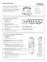
Speaker Location
Below are examples of room coverage for two and four speaker installations. For more than 4 speakers, space
the next row(s) accordingly.
Ceiling Speakers: Locate and identify the center most tile in each quadrant.
Wall Speakers: First observe the shape of the room: ceiling height, door locations, windows, mounting surface,
and seating area. Ordinary installation would be to locate the speakers on each side wall beginning
at the front row of listeners, approximately 6–7 feet above the floor.

Forum
™
Speaker Installation
9
www.teachlogic.com | support@teachlogic.com | (760) 631-7800
Connection of speakers
The IMA-240 has two channels of amplified audio, rated for a minimum 4-ohm speaker load (two 8-ohm
speakers each, connected in parallel provide 4 ohms impedance).
There is one blue phoenix style speaker connector on the back panel, providing two pairs of speaker
terminals.

Forum
™
Ceiling Sensor Installation
10
www.teachlogic.com | support@teachlogic.com | (760) 631-7800
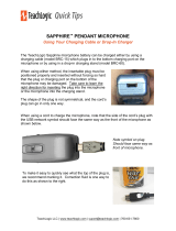
Installation of Infrared (IR) Ceiling Sensor (ICS-55)
The ideal mounting location is in the center of the room's ceiling. The ideal installation is flush mounted on
a white, reflective ceiling like suspended acoustic ceiling tiles. This will ensure 360º coverage and will
minimize the transmission distance for more reliable performance.
For additional coverage, or in large rooms, a second IR sensor may be placed on ceiling or a wall and
connected to the second sensor input. As many as three sensors may be powered by the amplifier (use a
wye adapter for two of them to connect to one input). The max cable length is 100 ft.
Installation 1 – Attach to T-bar rail
Installation 2 – Concrete or Drywall Surface
Installation 3 – Wood Surface
FINAL STEP: Route sensor cable to amplifier and plug into one of the amplifier’s two sensor inputs. An
illuminated green LED will indicate that the sensor is receiving power from the amplifier.

Forum
™
Anti-Hum Feature
11
www.teachlogic.com | support@teachlogic.com | (760) 631-7800
Anti-Hum Feature
The rear panel input port labeled “Computer” has a switchable
feature to eliminate or reduce hum sounds often present when
computers are connected to external amplifiers. The hum is
known as a ground loop hum and may be present if the
computer and amplifier have electrical grounding differences.
The telltale characteristic is that it is 60 hertz (a somewhat low
tone.) Inside the amplifier is a ground isolating balun that may
reduce or eliminate the hum when switched ON. If not needed,
it is getter the leave switched OFF as the sound quality for the
connected device will be slightly better in this case.

Forum
™
Video Conferencing Connection
12
www.teachlogic.com | support@teachlogic.com | (760) 631-7800
Video Conferencing Connection
All media devices connected to the TeachLogic amplifier (including microphones) will be heard by online
viewers. All audio—including devices connected directly to the computer—will play through the TeachLogic
amplifier/receiver in the classroom.
• Amplifier Output > Computer Microphone Input: enables online leaners to hear classroom audio including
wireless microphones
• Computer Speaker Output > Amplifier Input: enables classroom learners to hear computer & conference
audio
• For more detailed instructions, visit https://teachlogic.com/distance-learning/.

Forum
™
Final Setup
13
www.teachlogic.com | support@teachlogic.com | (760) 631-7800
Final Setup
Now that the system is installed and connected, turn the system “ON” and test its performance.
The testing will be done using an IR (infrared) microphone (Sapphire™ or Handheld) to confirm good
connectivity.
AMPLIFIER
• Connect power supply to amplifier, then plug into outlet.
• Turn the amplifier ON by pushing the power button. The “TL” illuminates solid blue when the amplifier is
powered ON.
• Confirm there is power to the IR ceiling sensor: A green LED on edge of sensor should be illuminated
that indicates it is receiving power.
• Set all gain/volume dials to mid scale (12 o’clock position)
IRT-60 (SAPPHIRE) MICROPHONE SETUP
• Confirm "Ch A" volume dial is at mid scale (12 o’clock position)
• Slide gain/volume control switch on Sapphire to "Normal" setting.
• Press and hold power mic button until the LED light illuminates.
• Observe Sapphire power LED. Solid blue indicates power is on and mic is transmitting.
• Observe amplifier Ch A indicator LED. It should be green, indicating a connection between the
microphone and ceiling sensor.
• If using two IRT-60 microphones in the same room, one must be changed to channel B to avoid
interference. Watch the how-to video on teachlogic.com/resources.
Note: Next steps should be performed with a second person as the listener
• Stand under or in front of a speaker.
• Hold the microphone with the top at your collarbone and observe the speaker volume in the room by
speaking in a natural voice.
• Raise the volume on Ch A until feedback begins, then reduce volume to an acceptable level and until
indications of feedback have stopped.
• Walk around the room while talking into microphone to confirm good connectivity and sound levels and
lack of feedback under/in front of each speaker.
IRH-35 HANDHELD MICROPHONE SETUP
• Confirm "Ch B" volume control is set to mid-scale (12 o’clock position)
• Power on microphone using ON/OFF switch.
• Observe LED above mic switch. Solid green indicates power is on and ready to use.
• Observe amplifier Ch B indicator LED. It should be green, indicating a connection between the
microphone and IR ceiling sensor.
• Hold the microphone about 3 inches from the mouth, above chin level and perform voice test.
• Raise the volume on “Ch B” until feedback begins, then reduce volume to eliminate all feedback.
• Walk around the room while talking into the microphone to confirm good connectivity and sound
under/in front of each speaker without feedback.
Once complete, charge microphones so they are ready for use.

Forum
™
Power Button Lights/Standby Function
14
www.teachlogic.com | support@teachlogic.com | (760) 631-7800
Power Button Operation
The main power button on the amplifier’s front panel has multiple indications as shown in the table below.
Red, solid
Off state; power is still supplied to USB port on back
panel used to charge microphones
Blue, solid On
Blue flashing Page received and audio sources muted
Amber, solid In Standby (or “Sleep”) mode. See below
Red, flashing Muted by Fire Alarm Mute Input
Purple, flashing
System in Ducked mode with all line inputs lowered in
volume to allow microphones to be better heard. The
Sapphire mic on Channel A can trigger this “Teacher
Priority” mode with a press of its priority button (toggles
mode on and off)
Green/Red flashing
Indications of Security Alert pulse mode (see section
above)
Green Flashing Security Alert activated
System Standby Function
Standby Mode is a feature that reduces power consumption after the amplifier has not been used to amplify audio
signal for a period of two hours. After entering the automatic standby mode, the amplifier displays an amber light
at power button.
Normal ON mode may be resumed by
1. speaking into a microphone that is on,
2. sending an audio signal into one of the line inputs *such as a projector or flat panel audio signal), or
3. pressing the power button once.
It may take a few seconds for the normal mode to resume after one of these actions is taken. A page signal can
also “wake” the amplifier, but to hear the full first page of a morning, be sure to wake it first with one of the methods
above since, or the initial several seconds may be missed if there are no other paging speakers provided to deliver
the page audio.

Forum
™
Troubleshooting
`
15
Troubleshooting
Problem
Solution
System will not power “ON” Verify AC power; the power button will illuminate Blue when turned ON
Check if system has been unplugged; reconnect to power outlet or
use another device to ascertain power available at outlet
Check circuit breaker
Call maintenance for assistance
System is turned “ON” but there
is no sound
or
System is in standby and does
not “wake up”
Turn “ON” microphone/ transmitter; the “TL” power button will illuminate
to solid Blue when turned ON
If the power button is illuminated red, the battery is low
Ensure the mic is not muted (blinking light on mic indicates it is muted)
Ensure gain/volume control knob on amplifier/receiver is turned up to
mid-scale (12 o’clock position)
On amplifier/receiver, ensure a green LED is illuminated just below Ch
A or Ch B knob (depending on the microphone used).
If no LED is illuminated:
• Check the green LED on the ceiling sensor
If sensor LED is not lit:
• Sensor has been disconnected (check cable plug ends), or
• Power output to sensor has failed (Sensor or amplifier may need
to be replaced)
Voice is distorted and/or signal
drop-out occurs
Verify that the sensor is not being covered
Verify there is no obstruction between microphone and sensor
Ensure there is no direct sunlight on sensor
Ensure no other IR mics in room are turned on
If sensor is mounted on a dark surface or without a flush ceiling
surface, reception can be hampered.

Forum
™
Specifications
`
16
Forum™ (IMA-240)
Amplifier Output Power
50 W RMS, 2 x 25 W channels
Receiver Input
Infrared FM, 2 wireless mic channels
Modulation
Wide-band FM
Reception Frequencies
Ch. A: 2.08 MHz | Ch. B: 2.54 MHz
Deviation
10 kHz Nominal, 25 kHz Maximum
De-emphasis
50 µs
Tone Key
32.768 kHz
Infrared Wavelength
850 nm
External Sensor Input
2, RCA, powered ports
Connectivity Coverage
1,600 sq ft per sensor, up to 3 sensors supported
Total Harmonic Distortion
<1% @ 1 kHz
Frequency Response
40 Hz –18 kHz, ± 3 dB
Line Level Inputs
Rear Panel: DVD input, dual RCA, 0dB
Rear Panel: Computer input, 3.5mm, -10 dB
Front panel: Auxiliary input, 3.5 mm, -10 dB
Anti-Hum Balun
Present on Computer input
Line Outputs
Front panel: 3.5mm w/ gain control
Rear Panel: 3.5 mm w/ +10 dB gain control
Output Impedance
Rated Load: 4Ω minimum impedance
Equalization
3-band, ±10 dB
S/N Ratio
65 dB
Speaker Connection
4-pin Phoenix Connectors
Charger Output
5 VDC, USB
Power Supply
19 VDC / 3.5 A CE, CSA and UL Listed
Dimensions
8 1/2” W x 1 3/4” H x 7 1/2” D
Weight
1.7 lb.
Power Supply (AC-36)
Type
Regulated Switching Power Supply, CE, CSA and UL listed
Input Voltage
100-240 volts AV, 47-63 Hz
Output Voltage
19 VDC, 3.43 A
Power Output
65 watts max

Forum
™
Specifications
`
17
Sapphire (IRT-60) microphone/transmitter specs
Transmission Carrier
Infrared
Transmission Frequencies
2.08 MHz & 2.54 MHz
Channel Selection
Field Switchable
Transmitting Diodes
Six
Wavelength
850 nm
Modulation
FM Wide-Band
Frequency Response
100 Hz - 10 KHz
Pilotone Frequency
32.768 KHz
Peak Deviation
± 25 KHz
Dynamic Range
95.5 dB @ 2.8% THD
Operating Range
60 Ft. line of sight
Latency (mic to speakers)
0.87 ms
Battery Used
Lithium-ion polymer (3.7V / 620mAh)
Battery Life
8 hr/Charge
External Power Charger
5V DC Micro USB Connector
Transmission Angle
180° Conical
User Controls
Power (On/Off)
Press & Hold
Mute Switch (On/Off)
Momentary Press (blinks when muted)
Addt’l Mic Gain Control
Normal, -3dB, -6dB
Audio Source Vol./Gain
Increase, Decrease
Channel Select
(A or B) in battery compartment
External Mic/Aux Input
3.5 mm Line Level
Dimensions (H x W x D)
3.5” x 1.25” x 0.75”
Weight
1.4 oz including battery
Handheld (IRT-35) microphone/transmitter specs
Transmission Carrier
Infrared
Transmission Frequencies
2.08 MHz & 2.54 MHz
Channel Selection
Field Switchable
Transmitting Diodes
Ten
Wavelength
850 nm
Modulation
FM Wide-Band
Pilotone Frequency
32.768 KHz
Peak Deviation
± 25 KHz
Operating Range
50 ft. line of sight
Power Switch (Slide)
On/Off
Battery Charge Level (LED)
Green: Full | Orange: Medium | Red: Low
Battery Life
Approx. 7 Hr./Charge
Dimensions
2.125” dia. (Head), 1.4375” dia. (Body), 9.625” H
Weight
10.3 oz. w/ Battery

P/N UMM-240 20220301
541 Main St. Longmont, Suite B, CO 80501
TeachLogic.com | Support@TeachLogic.com | 760-631-7800
/