Toshiba RAS-24E2KVG-TR User manual
- Category
- Split-system air conditioners
- Type
- User manual

AIR CONDITIONER (SPLIT TYPE)
INSTALLATION MANUAL
1133550108
Indoor unit
RAS-24E2KVG-TR
Outdoor unit
RAS-24E2AVG-TR
R32
ENGLISH
TÜRKCE
IM_1133550108_EN_TR.indb 1IM_1133550108_EN_TR.indb 1 27/7/2565 BE 14:3327/7/2565 BE 14:33

CONTENTS
EN
İÇINDEKILER
TR
PRECAUTIONS FOR SAFETY ....................................................1
ACCESSORY PARTS ..................................................................5
INSTALLATION DIAGRAM OF INDOOR AND
OUTDOOR UNITS .......................................................................6
Optional Installation Parts .......................................................6
INDOOR UNIT ..............................................................................7
Installation Place .....................................................................7
Cutting a Hole and Mounting Installation Plate .......................7
How to Connect Remote Controller for Wire Operation ..........7
Piping and Drain Hose Installation ..........................................8
Indoor Unit Fixing ....................................................................9
Drainage ................................................................................10
OUTDOOR UNIT ........................................................................10
Installation Place ...................................................................10
Precautions about Installation in Regions
with Snowfall and Cold Temperatures ...................................10
Draining the Water .................................................................11
Refrigerant Piping Connection ..............................................11
Evacuating .............................................................................11
ELECTRICAL WORKS ..............................................................13
Wiring Connection .................................................................13
Power Supply and Connecting Cable Connection ................14
Power Supply Input Wiring Diagram .....................................15
OTHERS .....................................................................................16
Gas Leak Test........................................................................16
Remote Control A-B Selection ...............................................16
Test Operation .......................................................................16
Auto Restart Function Setting ...............................................16
APPENDIX .................................................................................17
GÜVENLİK ÖNLEMLERİ .............................................................1
AKSESUAR PARÇALARI ...........................................................5
İÇ VE DIŞ ÜNITENIN MONTAJ ŞEMASI ....................................6
İsteğe Bağlı Montaj Parçaları ..................................................6
İÇ ÜNİTE ......................................................................................7
Montaj Yeri ...............................................................................7
Bir Delik Açılması ve Montaj Plakasının Yerleştirilmesi ...........7
Kablolu Kullanım İçin Uzaktan Kumanda Bağlantısı
Nasıl Yapılır .............................................................................7
Boruların Bağlanması ve Boşaltma Hortumunun
Monte edilmesi ........................................................................8
İç Ünitenin Takılması ...............................................................9
Su Boşaltma ..........................................................................10
DIŞ ÜNİTE ..................................................................................10
Montaj Yeri .............................................................................10
Karlı ve Soğuk Bölgelerde Montaj İle İlgili Önlemler .............10
Suyun Boşaltılması ................................................................11
Soğutma Maddesi Boru Bağlantısı ........................................ 11
Boşaltma ...............................................................................11
ELEKTRİK İŞLERİ .....................................................................13
Bağlantı Kablosu ...................................................................13
Güç Kaynağı ve Bağlantı Kablosu Bağlantısı ........................14
Güç Beslemesi Girişi Kablo Şeması ......................................15
DİĞERLERİ ................................................................................16
Gaz Kaçağı Testi ...................................................................16
Uzaktan Kumanda ile A-B Seçimi ..........................................16
Test İşlemi .............................................................................16
Otomatik yeniden başlama işlevi ayarı ..................................16
EK...............................................................................................17
IM_1133550108_EN_TR.indb 2IM_1133550108_EN_TR.indb 2 27/7/2565 BE 14:3327/7/2565 BE 14:33

EN
ES
FR
IT
DE
PT
PL
CZ
RU
CR
HU
TR
NL
GR
SV
FI
NO
DK
RO
BG
EE
LV
SK
SI
1
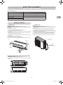
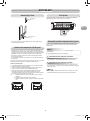
PRECAUTIONS FOR SAFETYPRECAUTIONS FOR SAFETY
Read the precautions in
this manual carefully before
operating the unit.
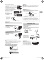
This appliance is fi lled with R32.
Warning indications on the air conditioner unit
Warning indication Description
CAUTION
BURST HAZARD
Open the service valves before the operation,
otherwise there might be the burst.
• Before installation, please read these precautions for safety carefully.
• Be sure to follow the precautions provided here to avoid safety risks.
The symbols and their meanings are shown below.
WARNING : It indicates that incorrect use of this unit may cause severe injury or
death.
CAUTION : It indicates that incorrect use of this unit may cause personal injury
(*1), or property damage (*2).
*1: Personal injury means a slight accident, burn, or electrical shock
which does not require admission or repeated hospital treatment.
*2: Property damage means greater damage which affects assets or
resources.
For general public use
Power supply cord and connecting cable of appliance use shall be at least
polychloroprene sheathed fl exible cord (design H07RN-F) or cord designation
60245 IEC66. (Shall be installed in accordance with national wiring regulations.)
This appliance must be connected to the main power supply by means of a circuit
breaker or a switch with a contact separation of at least 3 mm in all poles.
CAUTION To disconnect the appliance from the main power supply
IM_1133550108_EN_TR.indb 1IM_1133550108_EN_TR.indb 1 27/7/2565 BE 14:3327/7/2565 BE 14:33

2
WARNING
• Never modify this unit by removing any of the safety guards or bypassing any of
the safety interlock switches.
• Do not install in a place which cannot bear the weight of the unit.
Personal injury and property damage can result if the unit falls.
• Before doing the electrical work, attach an approved plug to the power supply
cord.
Also, make sure the equipment is properly earthed.
• Appliance shall be installed in accordance with national wiring regulations.
If you detect any damage, do not install the unit. Contact your dealer
immediately.
• Do not use any refrigerant different from the one specifi ed for complement or
replacement.
Otherwise, abnormally high pressure may be generated in the refrigeration
cycle, which may result in a failure or explosion of the product or an injury to
your body.
DANGER
• FOR USE BY QUALIFIED PERSONS ONLY.
• TURN OFF MAIN POWER SUPPLY BEFORE ATTEMPTING ANY ELECTRICAL
WORK. MAKE SURE ALL POWER SWITCHES ARE OFF.
FAILURE TO DO SO MAY CAUSE ELECTRIC SHOCK.
• CONNECT THE CONNECTING CABLE CORRECTLY. IF THE CONNECTING
CABLE IS CONNECTED WRONGLY, ELECTRIC PARTS MAY BE DAMAGED.
• CHECK THE EARTH WIRE THAT IT IS NOT BROKEN OR DISCONNECTED
BEFORE INSTALLATION.
• DO NOT INSTALL NEAR CONCENTRATIONS OF COMBUSTIBLE GAS OR
GAS VAPORS.
FAILURE TO FOLLOW THIS INSTRUCTION CAN RESULT IN FIRE OR
EXPLOSION.
• TO PREVENT OVERHEATING THE INDOOR UNIT AND CAUSING A FIRE
HAZARD, PLACE THE UNIT WELL AWAY (MORE THAN 2 M) FROM HEAT
SOURCES SUCH AS RADIATORS, HEATERS, FURNACE, STOVES, ETC.
• WHEN MOVING THE AIR CONDITIONER FOR INSTALLING IT IN ANOTHER
PLACE AGAIN, BE VERY CAREFUL NOT TO GET THE SPECIFIED
REFRIGERANT (R32) WITH ANY OTHER GASEOUS BODY INTO THE
REFRIGERATION CYCLE. IF AIR OR ANY OTHER GAS IS MIXED IN THE
REFRIGERANT, THE GAS PRESSURE IN THE REFRIGERATION CYCLE
BECOMES ABNORMALLY HIGH AND IT RESULTINGLY CAUSES BURST OF
THE PIPE AND INJURIES ON PERSONS.
• IN THE EVENT THAT THE REFRIGERANT GAS LEAKS OUT OF THE PIPE
DURING THE INSTALLATION WORK, IMMEDIATELY LET FRESH AIR
INTO THE ROOM. IF THE REFRIGERANT GAS IS HEATED BY FIRE OR
SOMETHING ELSE, IT CAUSES GENERATION OF POISONOUS GAS.
IM_1133550108_EN_TR.indb 2IM_1133550108_EN_TR.indb 2 27/7/2565 BE 14:3327/7/2565 BE 14:33

EN
ES
FR
IT
DE
PT
PL
CZ
RU
CR
HU
TR
NL
GR
SV
FI
NO
DK
RO
BG
EE
LV
SK
SI
3
• Do not use means to accelerate the defrosting process or to clean, other than
those recommended by the manufacturer.
• The appliance shall be stored in a room without continuously operating ignition
sources (for example: open fl ames, an operating gas appliance or an operating
electric heater).
• Be aware that refrigerants may not contain an odour.
• Do not pierce or burn as the appliance is pressurized. Do not expose the
appliance to heat, fl ame, sparks, or other sources or ignition. Else, it may
explode and cause injury or death.
• For R32 model, use pipes, fl are nut and tools which is specifi ed for R32
refrigerant. Using of existing (R22) piping, fl are nut and tools may cause
abnormally high pressure in the refrigerant cycle (piping), and possibly result in
explosion and injury.
• Thickness of copper pipes used R32 must be more than 0.8 mm.
Never use copper pipes thinner than 0.8 mm.
• After completion of installation or service, confi rm there is no leakage of
refrigerant gas. It may generate toxic gas when the refrigerant contacts with fi re.
• Comply with national gas regulations.
WARNING
• After installation work, make sure below before operation.
- Connection pipes are connected properly and no leakage.
- Packed valves are fully open.
Running compressor without open packed valves may cause abnormal high
pressure and parts failure.
Leakage at connection piping may suck air and make further high pressure
cause burst and injure.
• During pump down work make sure below process.
- Don’t mix air into the refrigerant cycle.
- Stop the compressor before removing piping after packed valves are fully
closed.
Removing piping under the compressor running and packed valves open, air
might be sucked and refrigeration cycle pressure becomes abnormally high, and
it causes burst or injury on persons.
IM_1133550108_EN_TR.indb 3IM_1133550108_EN_TR.indb 3 27/7/2565 BE 14:3327/7/2565 BE 14:33

4
REQUIREMENT OF REPORT TO THE LOCAL POWER SUPPLIER
Please make absolutely sure that the installation of this appliance is reported
to the local power supplier before installation. If you experience any problems
or if the installation is not accepted by the supplier, the service agency will take
adequate countermeasures.
■Important information regarding the refrigerant used
This product contains fl uorinated greenhouse gases.
Do not vent gases into the atmosphere.
Refrigerant type: R32
GWP(1) value: 675 * (ex. R32 ref. AR4)
(1)GWP = global warming potential
The refrigerant quantity is indicated on the unit name plate.
* This value is based on F gas regulation 517/2014
CAUTION
• Exposure of unit to water or other moisture before installation could result in
electric shock.
Do not store it in a wet basement or expose to rain or water.
• After unpacking the unit, examine it carefully for possible damage.
• Do not install the unit at place where leakage of fl ammable gas may occur. In
case gas leaks and accumulates at surrounding of the unit, it may cause of fi re.
• Do not install in a place that can increase the vibration of the unit. Do not
install in a place that can amplify the noise level of the unit or where noise and
discharged air might disturb neighbors.
• To avoid personal injury, be careful when handling parts with sharp edges.
• Please read this installation manual carefully before installing the unit. It contains
further important instructions for proper installation.
• The manufacturer shall not assume any liability for the damage caused by not
observing the description of this manual.
IM_1133550108_EN_TR.indb 4IM_1133550108_EN_TR.indb 4 27/7/2565 BE 14:3327/7/2565 BE 14:33

EN
ES
FR
IT
DE
PT
PL
CZ
RU
CR
HU
TR
NL
GR
SV
FI
NO
DK
RO
BG
EE
LV
SK
SI
5
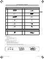
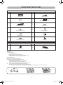
ACCESSORY PARTSACCESSORY PARTS
Indoor Unit
No. Part name No. Part name
1
Installation plate × 1
2
Wireless remote control × 1
3
Battery × 2
4
Remote control holder × 1
5
Ultra Fresh fi lter × 2
6
Mounting screw × 6
7
Flat head wood screw × 2
8
Owner’s Manual × 1
9
Installation Manual × 1
!
Screw × 2
"
Flat head wood screw × 1
#
Battery cover × 1
Outdoor Unit
No. Part name No. Part name
$
Drain nipple × 1
%
Cap water proof × 2
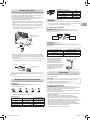
Air fi lters
Clean every 2 weeks.
1. Open the air inlet grille.
2. Remove the fi lters if they are on the air fi lter.
3. Vacuum or wash and then dry them.
4. Reinstall the fi lters and close the air inlet grille.
Ultra Fresh fi lter
Maintaining your strong purifying and revitalizing fi lter.
Clean every 6 months or when dust covers the fi lter.
1. Shake and blow with normal air or
2. Rinse the fi lter in water and dry it in under sunlight or in air.
(Do not wash or rinse with high pressure water)
3. Replace every 3 years or sooner. (P/N: RB-A701FE)
Note: Filter life depends on the level of impurities in your operating environment.
Higher levels of impurities may require more frequent cleaning and replacement.
In all cases, we recommend an additional set of fi lters to improve the purifying and deodorizing performance of your air conditioner.
Filter
IM_1133550108_EN_TR.indb 5IM_1133550108_EN_TR.indb 5 27/7/2565 BE 14:3327/7/2565 BE 14:33

6
1
7
#
"
3
5
7
4
2
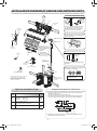
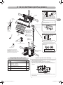
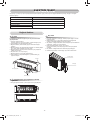
INSTALLATION DIAGRAM OF INDOOR AND OUTDOOR UNITSINSTALLATION DIAGRAM OF INDOOR AND OUTDOOR UNITS
Part
code Parts name Q’ty
A
Refrigerant piping
Liquid side : Ø6.35 mm
Gas side : Ø12.70 mm
One
each
BPipe insulating material
(polyethylene foam, 8 mm thick) 1
CPutty, PVC tapes One
each
Optional Installation Parts
• Secure the outdoor unit with fi xing bolts and nuts if the unit is likely to be
exposed to a strong wind.
• Use Ø8 mm or Ø10 mm anchor bolts and nuts.
• If it is necessary to drain the defrost water, attach drain nipple $ and cap
water proof % to the bottom plate of the outdoor unit before installing it.
w When using a multi-system outdoor unit, refer to the installation manual
provided with the model concerned.
Fixing bolt arrangement of outdoor unit
The auxiliary piping can be connected to
the left, rear left, rear right, right, bottom
right or bottom left.
Right
Rear
right
Bottom
right
Rear
left Bottom left
Left
Insulate the refrigerant pipes separately
with insulation, not together.
8 mm thick heat resisting
polyethylene foam
Batteries
Flat head
wood screw
Remote control holder
Vinyl tape
Apply after carrying
out a drainage test.
Wireless remote control Saddle
Extension drain hose
(Not available, provided
by installer)
Shield pipe
(Attach to the front panel.)
Air fi lter
Hook
Installation
plate
Hook
50 mm or more
300 mm or more
170 mm or more
600 mm or more
100 mm or more
100 mm or more
600 mm or more
600 mm or more
The provided Remote Controller is a wireless
type, which also can be used as a wire.
Please see “How to Connect The Remote
Controller for Wired Operation”, in case of
wired control is required.
Cut out a piece of SPACER from indoor
unit packaging box, roll it and insert
between the indoor unit and wall to tilt
the indoor unit for better operation.
For the rear left, bottom left and left piping
Wall
Make sure to run the drain hose sloped
downward.
Do not allow the drain hose to get slack.
Cut the piping
hole sloped
slightly.
Refrigerant piping
must be protected
from physical
damage.
Install a plastic
cover or equivalent.
Filter
Flat head
wood screw
Flat head
wood screw
Battery
cover
125 mm108 mm
28 mm
320 mm
600 mm
90 mm
Drain outlet
86 mm
102 mm
Air outlet
Air inlet
340 mm
IM_1133550108_EN_TR.indb 6IM_1133550108_EN_TR.indb 6 27/7/2565 BE 14:3327/7/2565 BE 14:33

EN
ES
FR
IT
DE
PT
PL
CZ
RU
CR
HU
TR
NL
GR
SV
FI
NO
DK
RO
BG
EE
LV
SK
SI
7
6
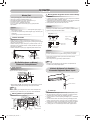
INDOOR UNITINDOOR UNIT
Installation Place
• Direct sunlight to the indoor unit’s wireless receiver should be avoided.
• The microprocessor in the indoor unit should not be too close to RF
noise sources.
(For details, see the owner’s manual.)
Remote control
• A place where there are no obstacles such as a curtain that may block the
signal from the indoor unit
• Do not install the remote control in a place exposed to direct sunlight or
close to a heating source such as a stove.
• Keep the remote control at least 1 m apart from the nearest TV set or
stereo equipment. (This is necessary to prevent image disturbances or
noise interference.)
• The location of the remote control should be determined as shown below.
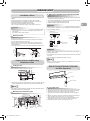
Cutting a Hole and Mounting
Installation Plate
NOTE
• When drilling a wall that contains a metal lath, wire lath or metal plate, be sure
to use a pipe hole brim ring sold separately.
Cutting a hole
When installing the refrigerant pipes from the rear
Mounting the installation plate
When the installation plate is directly mounted
on the wall
1. Securely fi t the installation plate onto the wall by screwing it in the upper and
lower parts to hook up the indoor unit.
2. To mount the installation plate on a concrete wall with anchor bolts, use the
anchor bolt holes as illustrated in the below fi gure.
3. Install the installation plate horizontally in the wall.
When installing the installation plate with a mounting screw, do not use the
anchor bolt holes. Otherwise, the unit may fall down and result in personal
injury and property damage.
1. After determining the pipe hole position on the mounting plate (¨), drill
the pipe hole (Ø65 mm) at a slight downward slant to the outdoor side.
• A place which provides the spaces around the indoor unit as shown in the
diagram
• A place where there are no obstacles near the air inlet and outlet
• A place which allows easy installation of the piping to the outdoor unit
• A place which allows the front panel to be opened
• The indoor unit shall be installed at least 2.5 m height.
Also, it must be avoided to put anything on the top of the indoor unit.
CAUTION
54 °
45°
06 °
(Side view) (Top view)
Indoor unit
Reception range
Remote
control
Remote
control
Reception
range
Indoor unit
CAUTION
Failure to fi rmly install the unit may result in personal injury and property
damage if the unit falls.
• In case of block, brick, concrete or similar type walls, make 5 mm dia. holes
in the wall.
• Insert clip anchors for appropriate mounting screws 6.
NOTE
• Secure four corners and lower parts of the installation plate with 4 to 6
mounting screws to install it.
CAUTION
Installation plate
(Keep horizontal direction.)
5 mm dia. hole
Clip anchor
(local parts)
Mounting screw
Ø4 mm x 25R
Anchor bolt
Projection
15 mm or less
m from the right side edge is
e center of pipe hole
35 120 180 240
The center of the pipe hole
is above the arrow.
Pipe hole
Ø65 mm
23 mm
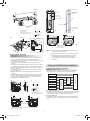
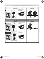
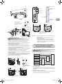
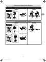
1. Open two screw caps and securely remove two screws at the front panel.
2. Slightly open the lower part of the front panel then pull the upper part of
the front panel toward you to remove it as shown on fi gure 1.
3. Arrange the control wire as detail and specifi cation as shown on fi gure
2.
4. Securely connect the control wire to terminal of Display unit as shown on
fi gure 3 (tighten fi rmly but not over 0.12 N·m (0.01 kgf·m)).
5. Set the control wire out from indoor unit same portion as power supply
and connecting cable as shown on fi gure 3. (Notch for wire out)
6. Reassembly the indoor unit by reverse process of 1 to 2.
Indoor unit
Control wire
Remote controller
How to Connect Remote Controller
for Wire Operation
For indoor unit
61
Hook
Hook
Hook
Pipe hole
Pipe hole
Installation plate
Mounting
screw
Weight
Indoor unit
Thread
Anchor bolt holes
50
40
170
132
23
Ø65 mm
300
85
IM_1133550108_EN_TR.indb 7IM_1133550108_EN_TR.indb 7 27/7/2565 BE 14:3327/7/2565 BE 14:33

8
Piping and Drain Hose Installation
* Since dewing results in a machine trouble, make sure to insulate both
connecting pipes. (Use polyethylene foam as insulating material.)
Piping and drain hose forming
1. Die-cutting front panel slit
Cut out the slit on the left or right side of the front panel for the left or right
connection and the slit on the bottom left or right side of the front panel
for the bottom left or right connection with a pair of nippers.
Rear right
Rear left
Bottom left
Left
Bottom right
Right
Die-cutting
front panel slit
Changing
drain hose
Piping preparation
2. Changing drain hose
For leftward connection, bottom-leftward connection and rear-leftward
connection’s piping, it is necessary to change the drain hose and drain
cap.
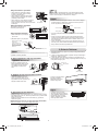
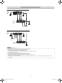
1. Remove cover of remote controller by sliding down and take it out.
2. If batteries are exist, please take them out. The combination of using
wire controller and batteries may cause of batteries explosion.
3. Make hole for insert control wire by use screwdriver break the plastic for
cover hole as shown on fi gure 4.
4. Insert control wire from rear side of remote controller as shown on
fi gure 5.
5. Fix control wire which arrange as shown on fi gure 6 and 7 to terminal
by provided screws (tighten fi rmly but not over 0.25 N·m (0.03 kgf·m)).
6. Set control wire through gutter way at rear side of remote controller as
shown on fi gure 8.
7. Fix provided screw (Ø3.1×16L) on the wall to hang remote controller as
shown on fi gure 9.
8. Mark and arrange hole for fi x below screw (Ø3.1×25L) as shown on
fi gure 9.
9. Assembly battery cover which provided with accessory bag then use
provide screw (Ø3.1×25L) to fi x battery cover together with wall as
shown on fi gure ! (tighten fi rmly but not over 0.15 N·m (0.02 kgf·m)).
10. Reassembly cover of remote controller.
For remote controller
*Remark : 1. Recommend to use double insulation lead wire for connect
remote control and air conditioner.
2. For wire operation, 1 remote control can control only 1 indoor
unit.
3. In wire operation, remote controller will return to initial
condition (PRESET, TIMER and CLOCK will return to
initial condition) when user shutdown power supply of air
conditioner.
2
3
* Wire size 28-22AWG
or 0.08-0.32 mm2
Outer diameter not over 4.7 mm,
control wire length 30 m. or less.
70 mm
5 mm
Terminal
Control wire
Notch for wire out
Control wire
Display unit
1
Screw
Screw cap
Screw
Front panel
45
Plastic for cover hole
* Terminals for wiring can be either on right (type A) or left (type B), depending
on the controller packed in carton.
Control wire
Type A Type B
Terminal
Control wire
6
7
* Wire size 28-22AWG
or 0.08-0.32 mm2
Outer diameter not over 4.7 mm,
control wire length 30 m. or less.
30 mm
10 mm
Control wire
Hole for hang
remote controller
Remote controller
Battery cover
Screw
Tighten fi rmly but not over
0.15 N·m (0.02 kgf·m)
Control wire
Screw (Ø3.1×16L)
for hang remote
controller
Wall
Remote controller
Screw (Ø3.1×25L)
for fi x battery cover
89
!
Type BType A
IM_1133550108_EN_TR.indb 8IM_1133550108_EN_TR.indb 8 27/7/2565 BE 14:3327/7/2565 BE 14:33

EN
ES
FR
IT
DE
PT
PL
CZ
RU
CR
HU
TR
NL
GR
SV
FI
NO
DK
RO
BG
EE
LV
SK
SI
9
How to remove the drain cap
Clip the drain cap by needle-nose
pliers and pull out.
How to remove the drain hose
• The drain hose can be removed by removing the
screw securing the drain hose and then pulling out
the drain hose.
• When removing the drain hose, be careful of any
sharp edges of steel plate. The edges can injuries.
• To install the drain hose, insert the drain hose
fi rmly until the connection part contacts with heat
insulator, and then secure it with original screw.
How to fi x the drain cap
1) Insert hexagon wrench (4 mm)
in a center head.
2) Firmly insert the drain cap.
Firmly insert the drain hose and drain cap; otherwise, water may leak.
CAUTION
Drain hose
Left-hand connection with piping
• Bend the connecting pipe so that it is laid within 43 mm above the wall
surface. If the connecting pipe is laid exceeding 43 mm above the wall
surface, the indoor unit may unstably be set on the wall.
When bending the connecting pipe, make sure to use a spring bender so
as not to crush the pipe.
Bend the connecting pipe within a radius of 30 mm.
To connect the pipe after installation of the unit (fi gure)
80
520 mm
420 mm
43 mm
Liquid side
Gas side
(To the forefront of fl are)
Outward form of indoor unit
R 30 mm (Use polisin (polyethylene)
core or the like for bending pipe.)
Use the handle of screwdriver, etc.
NOTE
If the pipe is bent incorrectly, the indoor unit may unstably be set on the wall.
After passing the connecting pipe through the pipe hole, connect the
connecting pipes to the auxiliary pipes and wrap the facing tape around
them.
In case of right or left piping
• After scribing slits inside of the front
panel with a knife or a making-off
pin, cut them with a pair of nippers
or an equivalent tool.
In case of bottom right or bottom left piping
• After scribing slits inside of the front
panel with a knife or a making-off pin,
cut them with a pair of nippers or an
equivalent tool.
Slit
Slit
CAUTION
• Bind the auxiliary pipes (two) and connecting cable with facing tape
tightly. In case of leftward piping and rear-leftward piping, bind the
auxiliary pipes (two) only with facing tape.
Indoor unit
Connecting cable
Auxiliary pipes
Installation plate
• Carefully arrange pipes so that any pipe does not stick out of the rear
plate of the indoor unit.
• Carefully connect the auxiliary pipes and connecting pipes to one
another and cut off the insulating tape wound on the connecting pipe
to avoid double-taping at the joint; moreover, seal the joint with the
vinyl tape, etc.
• Since dewing results in a machine trouble, make sure to insulate both
connecting pipes. (Use polyethylene foam as insulating material.)
• When bending a pipe, carefully do it, not to crush it.
1
1
2
Hook here.
Installation plate
Hook Press
(unhook)
Push Push
Indoor Unit Fixing
• For detaching the indoor unit
from the installation plate,
pull the indoor unit toward
you while pushing its bottom
up at the specifi ed parts.
1. Pass the pipe through the hole in the wall and hook the indoor unit on the
installation plate at the upper hook.
2. Swing the indoor unit to right and left to confi rm that it is fi rmly hooked up
on the installation plate.
3. While pressing the indoor unit onto the wall, hook it at the lower part on the
installation plate. Pull the indoor unit toward you to confi rm that it is fi rmly
hooked up on the installation plate.
The lower part of indoor unit may fl oat,
due to the condition of piping and you
cannot fi x it to the installation plate. In
that case, use the ! screws provided
to fi x the unit and the installation plate.
Information
!
Screw
Do not apply lubricating oil
(refrigerant machine oil)
when inserting the drain
cap. Application causes
deterioration and drain
leakage of the plug.
Insert a hexagon wrench
(4 mm).
No gap
IM_1133550108_EN_TR.indb 9IM_1133550108_EN_TR.indb 9 27/7/2565 BE 14:3327/7/2565 BE 14:33

10
Drain
guide
Space for pipes
Wall
Shield pipe
Inside the room
Drain hose Extension drain hose
Arrange the drain pipe for proper drainage from the unit.
Improper drainage can result in dew-dropping.
This air conditioner has the structure designed
to drain water collected from dew, which forms
on the back of the indoor unit, to the drain pan.
Therefore, do not store the power cord and other
parts at a height above the drain guide.
CAUTION
OUTDOOR UNITOUTDOOR UNIT
Installation Place
• A place which provides the spaces around the outdoor unit as shown in the
diagram
• A place which can bear the weight of the outdoor unit and does not allow an
increase in noise level and vibration
• A place where the operation noise and discharged air do not disturb your
neighbors
• A place which is not exposed to a strong wind
• A place free of a leakage of combustible gases
• A place which does not block a passage
• When the outdoor unit is to be installed in an elevated position, be sure to
secure its feet.
• The allowable length of the connecting pipe.
Models RAS-24E2AVG-TR
Chargeless Up to 15 m
Maximum length 20 m
Additional refrigerant charging 16 - 20 m (20 g / 1 m)
Maximum refrigerant charging 1.28 kg
• The allowable height of outdoor unit installation site.
Models RAS-24E2AVG-TR
Maximum height 12 m
• A place where the drain water does not raise any problems or with good
drainage.
• A place where it can be installed horizontally.
CAUTION
1. Install the outdoor unit without anything blocking the air discharging.
2. When the outdoor unit is installed in a place always exposed to strong
wind like a coast or on a high storey of a building, secure the normal
fan operation using a duct or a windshield.
3. In particularly windy areas, install the unit such as to avoid admission
of wind.
4. Installation in the following places may result in trouble.
Do not install the unit in such places.
• A place full of machine oil
• A saline-place such as the coast
• A place full of sulfi de gas
• A place where high-frequency
waves are likely to be generated
as from audio equipment, welders,
and medical equipment
Strong
wind
• Do not use the supplied drain nipple for draining water. Drain the water
from all the drain holes directly.
• To protect the outdoor unit from snow accumulation, install a holding
frame, and attach a snow protection hood and plate.
* Do not use a double-stacked design.
Precautions about Installation in Regions
with Snowfall and Cold Temperatures
Snow protection plate
Snow protection hood
Snow accumulation line
Holding frame
At least
50 cm
Install at least 50 cm
above the snow
accumulation line.
Anchor
bolts
Front
2. Put water in the drain pan and make sure that the water is drained out of
doors.
3. When connecting extension drain hose, insulate the connecting part of
extension drain hose with shield pipe.
Do not form the
drain hose into
a wavy shape.
Do not rise the
drain hose.
50 mm
or more
Do not put the
drain hose end
into water.
Do not put the
drain hose end
in the drainage ditch.
Drainage
1. Run the drain hose sloped downwards.
NOTE
• The hole should be made at a slight downward slant on the outdoor side.
When the outdoor unit is installed in a place where the drain water might
cause any problems, Seal the water leakage point tightly using a silicone
adhesive or caulking compound.
CAUTION
Use a scale having a precision with at least 10 g per index line when adding
the refrigerant.
Do not use a bathroom scale or similar instrument.
Precautions for adding refrigerant
IM_1133550108_EN_TR.indb 10IM_1133550108_EN_TR.indb 10 27/7/2565 BE 14:3327/7/2565 BE 14:33

EN
ES
FR
IT
DE
PT
PL
CZ
RU
CR
HU
TR
NL
GR
SV
FI
NO
DK
RO
BG
EE
LV
SK
SI
11
Flare nut
Half union
Externally
threaded side
Internally
threaded side
Use a wrench to secure. Use a torque wrench to tighten.
CAUTION
IMPERIAL (wing nut type)
Outer dia. of copper pipe R32
Ø6.35 1.5 to 2.0
Ø9.52 1.5 to 2.0
Ø12.70 2.0 to 2.5
Pipes thickness 0.8 mm or more
Align the centers of the connecting pipes and tighten the fl are nut as far as
possible with your fi ngers. Then tighten the nut with a spanner and torque
wrench as shown in the fi gure.
Tightening connection
Do not apply excess torque. Otherwise, the nut may crack depending on
the conditions.
(Unit : N·m)
Outer dia. of copper pipe Tightening torque
Ø6.35 mm 16 to 18 (1.6 to 1.8 kgf·m)
Ø9.52 mm 30 to 42 (3.0 to 4.2 kgf·m)
Ø12.70 mm 50 to 62 (5.0 to 6.2 kgf·m)
A
Die Pipe
Flare at
indoor unit side
Flare at
outdoor unit side
• Tightening torque of fl are pipe connections
The operating pressure of R32 is
higher than that of R22 (approx.
1.6 times). It is therefore necessary
to fi rmly tighten the fl are pipe
connecting sections (which connect
the indoor and outdoor units) up to the
specifi ed tightening torque. Incorrect
connections may cause not only a
gas leakage, but also damage to the
refrigeration cycle.
• Do not scratch the inner surface of the fared part when removing burrs.
• Flare processing under the condition of scratches on the inner surface of
fare processing part will cause refrigerant gas leak.
CAUTION
Evacuating
After the piping has been connected to the indoor unit, you can perform the
air purge together at once.
AIR PURGE
Evacuate the air in the connecting pipes and in the indoor unit using a
vacuum pump. Do not use the refrigerant in the outdoor unit.
For details, see the manual of the vacuum pump.
Be sure to use a vacuum pump with counter-fl ow prevention function so that
inside oil of the pump does not fl ow backward into pipes of the air
conditioner when the pump stops.
(If oil inside of the vacuum pump enters the air conditioner, which use R32,
refrigeration cycle trouble may result.)
1. Connect the charge hose from the manifold valve to the service port of the
packed valve at gas side.
2. Connect the charge hose to the port of the vacuum pump.
3. Open fully the low pressure side handle of the gauge manifold valve.
4. Operate the vacuum pump to start evacuating. Perform evacuating for
about 15 minutes if the piping length is 20 meters.
(15 minutes for 20
meters) (assuming a pump capacity of 27 liters per minute) Then confi rm that
the compound pressure gauge reading is –101 kPa (–76 cmHg).
5. Close the low pressure side valve handle of the gauge manifold valve.
6. Open fully the valve stem of the packed valves (both gas and liquid sides).
7. Remove the charging hose from the service port.
8. Securely tighten the caps on the packed valves.
Using a vacuum pump
Draining the Water
• Holes are provided on the base plate of the outdoor unit to ensure that the
defrost water produced during heating operations is drained off effi ciently.
If a centralized drain is required when installing the unit on a balcony or
wall, follow the steps below to drain off the water.
1. Proceed with water-proofi ng by installing the water-proof rubber caps in
the 2 elongated holes on the base plate of the outdoor unit.
[How to install the water-proof rubber caps]
1) Place four fi ngers into each cap, and insert the caps into the water
drain holes by pushing them into place from the underside of the base
plate.
2) Press down on the outer circumferences of the caps to ensure that
they have been inserted tightly. (Water leaks may result if the caps
have not been inserted properly, if their outer circumferences lift up or
the caps catch on or wedge against something.)
Drain nipple
Base plate
Water-proof rubber caps
(supplied with the outdoor unit)
2. Install the drain nipple and a commercially available drain hose (with
16 mm inside diameter), and drain off the water. (For the position where
the drain nipple is installed, refer to the installation diagram of the indoor
and outdoor units.)
• Check that the outdoor unit is horizontal, and route the drain hose at a
downward sloped angle while ensuring that it is connected tautly.
Commercially available
drain hose
Drain nippleBase plate
Do not use ordinary garden hose, but one can fl atten and prevent water
from draining.
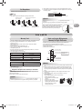
Refrigerant Piping Connection
Flaring
1. Cut the pipe with a pipe cutter.
90
Obliquity Roughness Warp
2. Insert a fl are nut into the pipe and fl are the pipe.
• Projection margin in fl aring : A (Unit : mm)
RIDGID (clutch type)
Outer dia.
of copper pipe R32 tool used Conventional tool
used
Ø6.35 0 to 0.5 1.0 to 1.5
Ø9.52 0 to 0.5 1.0 to 1.5
Ø12.70 0 to 0.5 1.0 to 1.5
Pipes thickness 0.8 mm or more
IM_1133550108_EN_TR.indb 11IM_1133550108_EN_TR.indb 11 27/7/2565 BE 14:3327/7/2565 BE 14:33

12
Packed valve at liquid side
Service port (Valve core (Setting pin))
Packed valve at gas side
Vacuum
pump
Vacuum pump adapter for
counter-fl ow prevention
Charge hose
Handle High
(Keep full closed)
Manifold valve
Pressure gauge
Compound pressure gauge
Handle Low
Charge hose
Connecting pipe
–101 kPa
(–76 cmHg)
CAUTION
• KEEP IMPORTANT 7 POINTS FOR PIPING WORK.
(1) Take away dust and moisture (inside of the connecting pipes).
(2) Tighten the connections (between pipes and unit).
(3) Evacuate the air in the connecting pipes using a VACUUM PUMP.
(4) Check gas leak (connected points).
(5) Be sure to fully open the packed valves before operation.
(6) Reusable mechanical connectors and fared joints are not allowed
indoors. When mechanical connectors are reused indoors, sealing
parts shall be renewed. When fared joints are reused indoors, the
fare part shall be refabricated.
(7) Don’t operate air conditioner in case no refrigerant in the system.
Packed valve handling precautions
• Open the valve stem all the way out, but do not try to open it beyond the
stopper.
Pipe size of Packed Valve Size of Hexagon wrench
12.70 mm and smallers A = 4 mm
15.88 mm A = 5 mm
Pump down process
1. Turn off the Air Conditioner system.
2. Connect the charge hose from the manifold valve to the service port of
the packed valve at gas side.
3. Turn on the Air Conditioner system in cooling operation more than
10 minutes.
4. Check the operating pressure of the system should be normal value.
(Ref. with product specifi cation)
5. Release the valve rod cap of both service valves.
6. Use the Hexagon wrench to turning the valve rod of Liquid side fully
close. (*Make sure no entering air into the system)
7. Continue operate Air Conditioner system until and the gauge of manifold
dropped into the range of 0.5 - 0 kgf/cm2
8. Use the Hexagon wrench to turning the valve rod of Gas side fully close.
And turn off the Air Conditioner system immediately thereafter.
9. Remove the gauge manifold from the service port of the packed valve.
10. Securely tighten the valve rod cap to the both service valves.
Should be check the compressor operating condition while pumping
down process. It must not any abnormal sound, more vibration.
It is abnormal condition appears and must turn off the Air Conditioner
immediately.
CAUTION
• Securely tighten the valve cap with torque in the following table:
Cap Cap Size (H) Torque
Valve Rod Cap
H17 - H19 14~18 N·m
(1.4 to 1.8 kgf·m)
H22 - H30 33~42 N·m
(3.3 to 4.2 kgf·m)
Service Port Cap
H14 8~12 N·m
(0.8 to 1.2 kgf·m)
H17 14~18 N·m
(1.4 to 1.8 kgf·m)
A
H
Hexagon wrench
is required.
Service Port Cap
Valve Rod Cap
IM_1133550108_EN_TR.indb 12IM_1133550108_EN_TR.indb 12 27/7/2565 BE 14:3327/7/2565 BE 14:33

EN
ES
FR
IT
DE
PT
PL
CZ
RU
CR
HU
TR
NL
GR
SV
FI
NO
DK
RO
BG
EE
LV
SK
SI
13
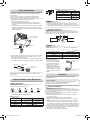
ELECTRICAL WORKSELECTRICAL WORKS
The power supply can be selected to connect to indoor unit or outdoor unit. Choose proper way and connect the power supply and connecting cable by follow
the instruction as following.
Indoor unit Outdoor unit
How to install the air inlet grille on the indoor
unit
• When attaching the air inlet grille, the contrary of the removed operation is
performed.
Wiring of the connecting cable can be carried out without removing the
front panel.
1. Remove the air inlet grille.
Open the air inlet grille upward and pull it toward you.
2. Remove the terminal cover and cord clamp.
3. Insert the connecting cable (according to the local cords) into the pipe hole
on the wall.
4. Take out the connecting cable through the cable slot on the rear panel so
that it protrudes about 20 cm from the front.
5. Insert the connecting cable fully into the terminal block and secure it tightly
with screws.
6. Tightening torque : 1.2 N·m (0.12 kgf·m)
7. Secure the connecting cable with the cord clamp.
8. Fix the terminal cover, rear plate bushing and air inlet grille on the indoor
unit.
Cord clamp
Terminal cover
Screw
Screws
Air inlet grille
Front panel
1. Remove the valve cover, the electric parts cover and the cord clamp from
the outdoor unit.
2. Connect the connecting cable to the terminal as identifi ed by the
matching numbers on the terminal block of indoor and outdoor unit.
3. Insert the power cord and the connecting cable carefully into the terminal
block and secure it tightly with screws.
4. Use vinyl tape, etc. to insulate the cords which are not going to be used.
Locate them so that they do not touch any electrical or metal parts.
5. Secure the power cord and the connecting cable with the cord clamp.
6. Attach the electric parts cover and the valve cover on the outdoor unit.
Valve cover
Terminals block
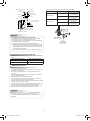
Model RAS-24E2KVG-TR
Power source 50Hz, 220 – 240V Single phase
Maximum running current 12.00 A
Circuit breaker rating 20 A
Power supply cable H07RN-F or 60245 IEC66 (2.0 mm2 or more)
Connecting cable
Wiring Connection
IM_1133550108_EN_TR.indb 13IM_1133550108_EN_TR.indb 13 27/7/2565 BE 14:3327/7/2565 BE 14:33

14
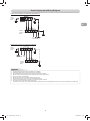
Power Supply and Connecting Cable Connection
Power Supply Input at Outdoor Unit Terminal Block (Recommend)
Indoor Unit Outdoor Unit
Connecting cable
connect to 1 2 3
Terminal block (L N 1 2 3)
Earth line
Connecting
cable
Connecting cable Stripping length of the
connecting cable
3
2
1
Earth line
50 mm
10 mm
70 mm
10 mm
123
LN
50 mm
60 mm
40 mm
45 mm
10 mm
10 mm
10 mm
10 mm
Earth line Earth line
Connecting cable Power supply cable
Power Supply Input at Indoor Unit Terminal Block (Optional)
Indoor Unit Outdoor Unit
Power supply cable
connect to L N
Terminal block (L N 1 2 3)
Earth line
Power supply
cable
Power supply cable Stripping length of the power
supply cable
N
L
Earth line
50 mm
10 mm
70 mm
10 mm
123
60 mm
45 mm
10 mm
10 mm
Earth line
Connecting cable
Connecting cable
connect to 1 2 3
Terminal block (L N 1 2 3)
Earth line
Power supply
cable Connecting
cable
Earth line
Connecting cable Stripping length of the
connecting cable
3
50 mm
Earth line
10 mm
70 mm
10 mm
IM_1133550108_EN_TR.indb 14IM_1133550108_EN_TR.indb 14 27/7/2565 BE 14:3327/7/2565 BE 14:33

EN
ES
FR
IT
DE
PT
PL
CZ
RU
CR
HU
TR
NL
GR
SV
FI
NO
DK
RO
BG
EE
LV
SK
SI
15
Power Supply Input Wiring Diagram
Power input at Outdoor Terminal Block (Recommend)
Indoor
Terminal
Block
Power input
Outdoor
Terminal
Block
Power input at Indoor Terminal Block (Optional)
Indoor
Terminal
Block
Power input
Outdoor
Terminal
Block
CAUTION
1. The power supply must be same as the rated of air conditioner.
2. Prepare the power source for exclusive use with air conditioner.
3. Circuit breaker must be used for the power supply line of this air conditioner.
4. Be sure to comply power supply and connecting cable for size and wiring method.
5. Every wire must be connected fi rmly.
6. Perform wiring works so as to allow a general wiring capacity.
7. Wrong wiring connection may cause some electrical part burn out.
8. Incorrect or incomplete wiring is carried out, it will cause an ignition or smoke.
9. This product can be connected to main power supply.
Connection to fi xed wiring : A switch which disconnects all poles and has a contact separation at least 3 mm must be incorporated in the fi xed wiring.
IM_1133550108_EN_TR.indb 15IM_1133550108_EN_TR.indb 15 27/7/2565 BE 14:3327/7/2565 BE 14:33

16
OTHERSOTHERS
Test Operation
To switch the TEST RUN (COOL) mode, press [RESET] button for
10 seconds. (The beeper will make a short beep.)
OPERATION /
RESET Button
Auto Restart Function Setting
This product is designed so that, after a power failure, it can restart
automatically in the same operating mode as before the power failure.
The product is shipped with Auto Restart function in the ON position.
Turn it OFF if this function is not required.
Information
How to turn OFF the Auto Restart Function
• Press and hold the [OPERATION] button on the indoor unit for 3 seconds
(3 Beep sound but OPERATION lamp does not blink).
How to turn ON the Auto Restart Function
• Press and hold the [OPERATION] button on the indoor unit for 3 seconds
(3 Beep sound and OPERATION lamp blink 5 time/sec for 5 seconds).
NOTE
• In case of ON timer or OFF timer are set, AUTO RESTART OPERATION
does not activate.
Gas Leak Test
Check places for
the indoor unit.
Check places for
the outdoor unit.
• Check the fl are nut connections for the gas leak with a gas leak detector
or soap water.
Remote Control A-B Selection
• When two indoor units are installed in the same room or adjacent two
rooms, if operating a unit, two units may receive the remote control signal
simultaneously and operate. In this case, the operation can be preserved
by setting either one remote control to B setting. (Both are set to A setting
in factory shipment.)
• The remote control signal is not received when the settings of indoor unit
and remote control are different.
• There is no relation between A setting/B setting and A room/B room when
connecting the piping and cables.
To separate using of remote control for each indoor unit in case of 2 air
conditioner are installed near.
Remote Control B Setup.
1. Press [RESET] button on the indoor unit to turn the air conditioner ON.
2. Point the remote control at the indoor unit.
3. Push and hold [CHECK] button on the Remote Control by the tip of the
pencil. “00” will be shown on the display (Picture 1).
4. Press [MODE] during pushing [CHECK]. “B” will show on the display
and “00” will disappear and the air conditioner will turn OFF. The Remote
Control B is memorized (Picture 2).
Note : 1. Repeat above step to reset Remote Control to be A.
2. Remote Control A have not “A” display.
3. Default setting of Remote Control from factory is A.
21
IM_1133550108_EN_TR.indb 16IM_1133550108_EN_TR.indb 16 27/7/2565 BE 14:3327/7/2565 BE 14:33

EN
ES
FR
IT
DE
PT
PL
CZ
RU
CR
HU
TR
NL
GR
SV
FI
NO
DK
RO
BG
EE
LV
SK
SI
17
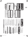
APPENDIXAPPENDIX
Work instructions
The existing R22 and R410A piping can be reused for
inverter R32 product installations.
WARNING
Confirming the existence of scratches or dents on
the existing pipes and confirming the reliability of
the pipe strength are conventionally referred to the
local site.
If the specified conditions can be cleared, it is
possible to update existing R22 and R410A pipes
to those for R32 models.
Basic conditions needed to reuse existing
pipes
Check and observe the presence of three conditions in
the refrigerant piping works.
1. Dry (There is no moisture inside of the pipes.)
2. Clean (There is no dust inside of the pipes.)
3. Tight (There are no refrigerant leaks.)
Restrictions for use of existing pipes
In the following cases, the existing pipes should
not be reused as they are. Clean the existing pipes
or exchange them with new pipes.
1. When a scratch or dent is heavy, be sure to use new
pipes for the refrigerant piping works.
2. When the existing pipe thickness is thinner than the
specified “Pipe diameter and thickness,” be sure to
use new pipes for the refrigerant piping works.
yThe operating pressure of R32 is high (1.6 times
that of R22). If there is a scratch or dent on the pipe
or a thinner pipe is used, the pressure strength may
be inadequate, which may cause the pipe to break
in the worst case.
* Pipe diameter and thickness (mm)
Pipe outer diameter Ø6.4 Ø9.5 Ø12.7
Thickness R32, R410A 0.8 0.8 0.8
R22
3. When the outdoor unit was left with the pipes
disconnected, or the gas leaked from the pipes and
the pipes were not repaired and refilled.
yThere is the possibility of rain water or air, including
moisture, entering the pipe.
4. When refrigerant cannot be recovered using a
refrigerant recovery unit.
yThere is the possibility that a large quantity of dirty
oil or moisture remains inside the pipes.
5. When a commercially available dryer is attached to the
existing pipes.
yThere is the possibility that copper green rust has
been generated.
6. When the existing air conditioner is removed after
refrigerant has been recovered.
Check if the oil is judged to be clearly different from
normal oil.
yThe refrigerator oil is copper rust green in color:
There is the possibility that moisture has mixed with
the oil and rust has been generated inside the pipe.
yThere is discolored oil, a large quantity of residue,
or a bad smell.
yA large quantity of shiny metal dust or other wear
residue can be seen in the refrigerant oil.
7. When the air conditioner has a history of the
compressor failing and being replaced.
yWhen discolored oil, a large quantity of residue,
shiny metal dust, or other wear residue or mixture of
foreign matter is observed, trouble will occur.
8. When temporary installation and removal of the air
conditioner are repeated such as when leased etc.
9. If the type of refrigerator oil of the existing air
conditioner is other than the following oil (Mineral oil),
Suniso, Freol-S, MS (Synthetic oil), alkyl benzene
(HAB, Barrel-freeze), ester series, PVE only of ether
series.
yThe winding-insulation of the compressor may
deteriorate.
NOTE
The above descriptions are results have been confirmed
by our company and represent our views on our air
conditioners, but do not guarantee the use of the existing
pipes of air conditioners that have adopted R32 in other
companies.
Curing of pipes
When removing and opening the indoor or outdoor unit for
a long time, cure the pipes as follows:
yOtherwise rust may be generated when moisture or
foreign matter due to condensation enters the pipes.
yThe rust cannot be removed by cleaning, and new
pipes are necessary.
Placement
location Term Curing manner
Outdoors 1 month or more Pinching
Less than 1 month Pinching or taping
Indoors Every time
Are there scratches or dents on the existing pipes?
Is it possible to operate the existing air conditioner?
yAfter the existing air conditioner is operated in cooling
mode for approx. 30 minutes or longer,* recover the
refrigerant.
yFor cleaning the pipes and recovering oil
yRefrigerant recovery: Pump down method
yRemove the existing air conditioner from the piping
and carry out flushing (nitrogen pressure 0.5 MPa) to
remove any remains inside of the pipe.
Note: In case of twin pipes, also be sure to flush the
branching pipe.
Connect the indoor / outdoor units to the existing pipe.
yUse a flare nut attached to the main unit for the indoor
/ outdoor units. (Do not use the flare nut of the existing
pipe.)
yRe-machine the flare machining size to size for R32.
y(Airtight test), Vacuum dry, Refrigerant charge, Gas
leak check
Test run
Was largely discolored oil or a large quantity
of remains discharged? (When the oil deteriorates,
the color of the oil changes to a muddy
or black color.)
Existing pipes: Cannot be used.
yUse new pipes.
Clean the pipes or use new pipes.
Piping necessary to change the flare nut / machining
size due to pipe compression
1) Flare nut width: H
H
(mm)
Copper pipe outer
diameter Ø6.4 Ø9.5 Ø12.7
For R32, R410A 17 22 26
For R22 Same as above 24
2) Flare machining size: A
A
(mm)
Copper pipe outer
diameter Ø6.4 Ø9.5 Ø12.7
For R32, R410A 9.1 13.2 16.6
For R22 9.0 13.0 16.2
Becomes a little larger for R32
Do not apply refrigerator oil to the flare surface.
(If there is discharge of remains, it is judged that a
large quantity of remains are present.)
YES
YES
NO
NO
NO
YES
Nitrogen gas pressure 0.5 MPa
IM_1133550108_EN_TR.indb 17IM_1133550108_EN_TR.indb 17 27/7/2565 BE 14:3327/7/2565 BE 14:33

1
GÜVENLİK ÖNLEMLERİGÜVENLİK ÖNLEMLERİ
Üniteyi çalıştırmadan önce bu
kılavuzdaki önlemleri dikkatlice
okuyun.
Bu aygıt R32 ile doldurulmuştur.
Klima ünitesindeki uyarı göstergeleri
Uyarı göstergesi Açıklama
DİKKAT
PATLAMA TEHLİKESİ
Çalıştırmadan önce servis vanalarını açın; aksi
halde patlama meydana gelebilir.
• Lütfen, montaj işleminden önce güvenliğiniz için bu önlemleri dikkatli bir şekilde
okuyun.
• Güvenlik risklerinden sakınmak için burada verilen önlemleri uyguladığınızdan
emin olun.
Semboller ve anlamları aşağıda gösterilmektedir.
UYARI : Bu ünitenin yanlış kullanılmasını ciddi yaralanma veya ölüme neden
olabileceğini gösterir.
DİKKAT : Bu ünitenin yanlış kullanılmasını kişisel yaralanma (*1) veya maddi
hasara (*2) neden olabileceğini gösterir.
*1: Kişisel yaralanma, hastaneye yatma veya tekrarlanan tedavi
gerektirmeyen hafi f kaza, yanık veya elektrik çarpması demektir.
*2: Maddi hasar, mal varlıkları veya kaynaklarını etkileyen daha büyük
hasar demektir.
Genel kullanım için
Aygıtın elektrik kablosu ve bağlantı kablosu en azından polikloropren madeni kılıfl ı
esnek kablo (tasarım H07RN-F) veya 60245 IEC66 no.lu kablo olmalıdır.
(Ulusal kablolama düzenlemelerine göre monte edilecektir.)
Bu aygıt ana güç kaynağına bir sigorta veya her kutbunda en az 3 milimetrelik bir
kontak mesafesi olan bir şalterle bağlanmalıdır.
DİKKAT Cihazın ana elektrik şebekesinden bağlantısının kesilmesi
IM_1133550108_EN_TR.indb 1IM_1133550108_EN_TR.indb 1 27/7/2565 BE 14:3327/7/2565 BE 14:33
Page is loading ...
Page is loading ...
Page is loading ...
Page is loading ...
Page is loading ...
Page is loading ...
Page is loading ...
Page is loading ...
Page is loading ...
Page is loading ...
Page is loading ...
Page is loading ...
Page is loading ...
Page is loading ...
Page is loading ...
Page is loading ...
Page is loading ...
Page is loading ...
-
 1
1
-
 2
2
-
 3
3
-
 4
4
-
 5
5
-
 6
6
-
 7
7
-
 8
8
-
 9
9
-
 10
10
-
 11
11
-
 12
12
-
 13
13
-
 14
14
-
 15
15
-
 16
16
-
 17
17
-
 18
18
-
 19
19
-
 20
20
-
 21
21
-
 22
22
-
 23
23
-
 24
24
-
 25
25
-
 26
26
-
 27
27
-
 28
28
-
 29
29
-
 30
30
-
 31
31
-
 32
32
-
 33
33
-
 34
34
-
 35
35
-
 36
36
-
 37
37
-
 38
38


Toshiba RAS-24E2KVG-TR User manual
- Category
- Split-system air conditioners
- Type
- User manual
Ask a question and I''ll find the answer in the document
Finding information in a document is now easier with AI
in other languages
Related papers
-
Toshiba RAS-10SAX User manual
-
-
-
Toshiba RAS-07PKVP-E Datasheet
-
-
-
-
-
-
Toshiba RAV-GV1101AT8P-E User manual
Other documents
-
Carrier 38EYV025M Installation guide
-
-
-
Daikin FVXG35K Owner's manual
-
LG UM30F User manual
-
-
Daikin R32 Split Series User manual
-
Hitachi air Home 400 Split Unit Air Conditioner User manual
-
LG LSN120HE Installation guide
-
Sinclair ASP-18AI User manual