Page is loading ...

OUTDOOR UNIT
CONTROLLER
(OUC)
Program 4.0 D
Operation and Fault Diagnosis
Issue 3, January 2005
QUALITY AIR CONDITIONING
SYDNEY
temperzone australia pty ltd
7A Bessemer St,
PO Box 6448, Delivery Centre
Blacktown, NSW 2148
Phone (02) 8822 - 5700
Fax (02) 8822 - 5711
Email [email protected]
MELBOURNE
Phone (03) 9551 - 7422
Fax (03) 9551 - 8550
ADELAIDE
Phone (08) 8333 - 1833
Fax (08) 8333 - 1844
PERTH
Phone (08) 9314 - 3844
Fax (08) 9314 - 3855
TOWNSVILLE
Phone (07) 4773 - 9566
Fax (07) 4773 - 9166
BRISBANE
Phone (07) 3399 - 2544
Fax (07) 3399 - 2577
NEWCASTLE
Phone (02) 4962 - 1155
Fax (02) 4961 - 5101
HOBART
Phone (03) 6272 - 0066
Fax (03) 6272 - 0506
01/05 Pamphlet No. 2446 Manx Press
AUCKLAND
temperzone Ltd
38 Tidal Road,
Mangere, Auckland.
Private Bag 93303, Otahuhu, N.Z.
Phone 0-9-279 5250
Fax 0-9-275 5637
Email [email protected]
WELLINGTON
Phone 0-4-569 3262
Fax 0-4-566 6249
CHRISTCHURCH
Phone 0-3-379 3216
Fax 0-3-379 5956
SINGAPORE
temperzone Ltd
1 Claymore Drive #08-13
Rear Block, Orchard Towers
Singapore 229594
Phone SNG 6733 - 4292
Fax SNG 6235 - 7180
Email [email protected]
Visit our website www.temperzone.biz

CONTENTS
Section Page
1Introduction 3
2Features 3
3Operation
3.1 Initial Power-Up & System Checks 3
3.2 Power on LED 3
3.3 Compressor Cycling Protection 3
3.4 Minimum Run Time Protection 4
3.5 Maximum Starts Per Hour Protection 4
3.6 High Pressure Protection 4
3.7 Loss of Refrigerant Protection 4
3.8 Low Pressure Protection 5
3.9 Service Valve Sensor Fault 5
3.10 Indoor Coil Ice Protection 5
3.11 HP Fan Speed Controller & Sensor 5
3.12 Head Pressure Sensor Fault 5
3.13 Outdoor Coil De-Ice Control 8
3.14 De-Ice Sensor Fault 9
3.15 Remote Common Fault Output 9
3.16 Repeat Fault Lockout Protection 9
3.17 Test Function 9
3.18 Commissioning Mode 10
3.19 Test Button Functions 10
4Dip Switch Settings 10
5Jumper 11
6Sensors Temperature vs Resistance Comparison 11 - 11 -
5 Jumper
There is a jumper fitted across two pins located next to the Test button. This must
remain fitted at all times for normal operation.
6 Temperature Sensors Temperature vs Resistance Comparison
Temperature °C Blue or Yellow Sensor Red Sensor
– 10 58 kohm 56 kohm
– 5 44 kohm 43 kohm
0 34 kohm 33 kohm
10 20 kohm 20 kohm
20 12.6 kohm 12.5 kohm
30 8 kohm 8 kohm
40 5.2 kohm 5.3 kohm
50 3.5 kohm 3.6 kohm
60 2.3 kohm 2.5 kohm
80 1.15 kohm 1.25 kohm
100 n/a 0.67 kohm
110 n/a 0.50 kohm
Do not test sensors while they are still plugged on to the control board.

- 3 -
1 Introduction
The temperzone Outdoor Unit Controller (OUC) is a pre-programmed electronic
controller of the outdoor unit's refrigeration system complete with system protection
features.
It responds to a 230 volt thermostat or temperature controller signal for the
compressor to run and a 230 volt 'Heat' signal that changes the operating mode
from Cooling to Heating.
2 Features
The OUC provides the following features:
- Compressor cycling protection
- Minimum run time (3 mins)
- High pressure protection
- Low pressure protection (if LP switch fitted)
- Loss of refrigerant protection
- HP fan speed control
- Indoor coil icing protection
- Run and fault LED indication
- Remote common fault output (if extra relay board fitted)
- Repeat fault lockout protection.
3 Operation
3.1 Initial Power-Up & System Checks
On initial power-up, the LEDs on the right hand side of the board will flash in
a pattern from the outside to the centre and back for 15 seconds. Nothing
will operate until this system check is complete. This is then followed by the
1 minute anti-rapid cycle time out.
3.2 Power On LED
Indicates power is reaching the controller board. It does not necessarily
indicate the board is functioning. If 230 volt is present at 'P' terminal and
Power LED is not illuminated then board is faulty and needs replacement.
3.3 Compressor Cycling Protection
Prevents the compressor from restarting too quickly. Ensures a minimum of
3 minutes rest from the last stop, to allow the system to equalise. This is not
adjustable.
Should a 230 volt signal be received at the COMP terminal during this period
then the (fault and De-ice safety,) LEDs on the right hand side of the
controller board will flash from bottom to top until the cycle has timed out.
- 10 -
3.18 Commissioning Mode
By pressing the Test button for a full 10 seconds in any mode the OUC will
be set in a 'Commissioning' mode. This reduces many of the running timers
(eg Minimum Run and Anti-Rapid Cycle) so that commissioning can be done
without continuously being impeded by time delays each time the Comp and
Heat signals are switched.
The Commissioning mode is allowed to run for 30 minutes after which time
normal operation resumes. The commissioning mode is indicated by the
column of LEDs flashing briefly every five seconds. Any fault lights will stay
on or flash differently so they will be obvious.
3.19 Test Button Fuctionality
Mode Press Time Accessible States Result
Commissioning 10 sec. Cooling Reduces minimum run
Heating & anti-rapid cycle timers.
Dead Zone Resets automatically after 30 mins.
Thermostat Off
Test Function < 1 sec. Dead Zone Runs 'Test' routine of functions
Thermostat Off (refer 3.17). Resets automatically.
Inhibition of 2 sec. Heating De-ice cycle allowable as soon as
De-ice Timer coil reaches –4°C.
Resets automatically.
Forced De-Ice 5 sec. Heating De-ice cycle starts immediately
if coil below 'STOP' temperature.
Resets automatically.
4 Dip Switch Settings
DP1 Factory set to OFF position to suit ducted units with
reasonable and high airflows.
Can be set to ON position if indoor units are ductless or have
very low airflows.
DP2 Factory set to OFF position to maintain a head pressure
equivalent to 42°C.
Can be set to ON position to maintain a head pressure
equivalent to 50°C.
DP3 Factory set to OFF position to prevent a de-ice cycle occurring
less than 30 minutes after intial start-up.
Can be set to ON position to allow a de-ice to occur
immediately on start-up.
DP4 Factory set to OFF position allows outdoor fan to cut off at
minimum speed setting.
Can be set to ON position so outdoor fan continues running at
minimum speed setting.

- 4 -
3.4 Minimum Run Time Protection
Ensures the compressor runs for at least 3 minutes to ensure oil is returned
to the compressor after start up. This is not adjustable.
If the 230 volt signal is removed from the COMP terminal during this period,
the (fault and safety) LEDs on the right hand side of the controller board will
flash from top to bottom until the cycle has timed out.
If however the 'Heat' signal is lost in 'Heat' mode or gained in 'Cool' mode
during this minimum run time period the compressor will be stopped and the
balance of the minimum run time added to the anti-rapid cycle time.
3.5 Maximum Starts Per Hour Protection
The Compressor Cycling Protection and Minimum Run Time functions
combined will only allow a maximum of 10 starts per hour.
3.6 High Pressure Protection
A High Pressure switch is connected to the controller board from which an
HP fault is indicated by the red safety trip 'H.P.' LED illuminated/flashing and
the compressor will be shut down for at least 3 minutes.
After 3 consecutive trips the compressor will be prevented from running for
30 minutes. This will be repeated after a further 3 trips. After another 3 trips
the compressor will be 'Locked Out' from running (the 'HP' LED remains
flashing) until power to the board (unit) is removed and restored.
3.7 Loss of Refrigerant Protection
On the cooling cycle the temperature at the service valve (suction on
cooling) is compared to the temperature of the HPC sensor and should there
be insufficient temperature difference, indicating loss of refrigerant, then a
fault is indicated by the red safety trip 'L.P.' LED illuminated/flashing and the
compressor will be shut down temporarily.
On the heating cycle the temperature at the service valve (discharge on
heating) is monitored and should this reach too high a temperature,
indicating loss of refrigerant, then an LP fault is indicated by the red safety
trip 'L.P.' LED illuminated/flashing and the compressor will be shut down
temporarily.
After 3 consecutive trips the compressor will be 'Locked Out' from running
until power to the board (unit) is removed and restored.
Note: Some units are fitted with manual reset thermal overloads on the
compressor/s. Should an 'L.P.' LED be illuminated, first check that one of
these overloads is not tripped as this could be the cause of the 'L.P.' fault signal.
The Service Valve sensor is located, either (i) in a pocket on the pipe
between the reversing valve and the service valve on split system outdoor
units, or (ii) on the indoor coil of packaged units.
- 9 -
2. By pressing the Test button for 5 seconds an immediate de-ice cycle
should occur, even if the 'Start' LED is not illuminated. It will not occur if
the ambient temperature is too high (above 12°C) and the 'Stop' LED is
illuminated. Normal de-ice function resumes once the de-ice is initiated.
This proves that the de-ice control is functioning correctly subject to
receiving the signal from the sensor.
If Test 2 is successful, but Test 1 was not, then check the sensor is located
correctly in the coil (embedded in the fins). Consider possibility of sensor
with incorrect calibration as a possible fault.
Should no de-icing cycle occur in either instance then the OUC board must
be treated as faulty and replaced. However if the LEDs illuminate and the
relays switch in the correct sequence but de-icing does not occur check the
Neutral link at the indoor unit, or possibly a faulty reversing valve.
If an extra wire has been run and connected between the 'De-ice' terminal on
the outdoor unit and terminal '1' of the indoor unit, then the link between
terminals 'N' and '1' of the indoor unit must be removed.
3.14 De-Ice Sensor Fault
A fault with the (blue lead) 'De-Ice' sensor, or the sensor not connected will
illuminate/flash the red 'De-ice' sensor fault LED. In 'Fault' mode the
compressor will not start in heating mode or will shutdown if running. The
compressor will operate in cooling mode.
3.15 Remote Common Fault Output
Two pins are provided to allow for the connection of an optional relay sub
board (temperzone item no 201 000 105) that will then in turn provide a 'no
volt' set of contacts that can be utilised as a common fault indication circuit.
3.16 Repeat Fault Lockout Protection
Faults that are detected, if repeated a number of times, will eventually result
in a 'Lockout' of the compressor from operation. Different faults have
different fail sequences that will lead to lockout and these are detailed under
their respective headings above. Repetitive sensor faults will also result in
shutdown and 'Lockout'. Flashing LEDs indicating faults will remain flashing
during a lockout of any device to aid in fault diagnosis.
3.17 Test Function
Once the initial power-up system check has been completed (refer 3.1) and
if neither cooling nor heating modes are active (i.e. dead zone condition), the
test button can be pressed momentarily and the controller will enter a test
sequence of LEDs and operating functions. Condenser fans and the
compressor should run for a few seconds and relays and contactors will be
heard or seen switching. At the end of this sequence normal operation will be
resumed. Do not repeat this sequence frequently as it may cause
damage to the compressor.

- 5 -
3.8 Low Pressure (Switch) Protection (if fitted)
If an optional Low Pressure Switch is connected to the controller board, an
LP fault is indicated by the red safety trip 'L.P.' LED illuminated/flashing and
the compressor will be shut down for 3 minutes.
After 3 consecutive trips the compressor will be 'Locked Out' from running
until power to the board (unit) is removed and restored (the 'LP' LED remains
flashing during lockout).
3.9 Service Valve Sensor Fault
A fault with the (red lead) 'Service Valve' sensor or the sensor not connected
will illuminate/flash the red 'S/V' sensor fault LED. In 'Fault' mode the
compressor will not start or will shutdown if running.
3.10 Indoor Coil Icing Protection
The 'Service Valve' sensor (Suction service valve on cooling cycle) is also
used as a protection for indoor coil ice up. At a pre-set low limit it shuts down
the compressor for 15 minutes and the 'Frost' safety trip LED will illuminate/
flash. After 4 consecutive trips the compressor will be 'Locked Out' from
running until power to the board (unit) is removed and restored.
3.11 Head Pressure Fan Speed Controller and Sensor
Cooling Mode
Controls the outdoor fan speed in the cooling cycle to maintain a condensing
temperature that can be set by Dip Switch 2 to either 42°C or 50°C.
The sensor is located in a return bend pocket on the outdoor coil.
The outdoor fan can be set to run continuously at minimum speed setting or
set to cut off (via Dip Switch 4). Continuous will give a more settled operation
but could in very cold outdoor ambient conditions lead to insufficient head
pressure. The choice of setting is therefore at the installers discretion. The
factory setting is for cut off.
Heating Mode
Reduces the outdoor fan speed when on the heating cycle in high ambients
to limit the head pressure and avoid nuisance 'HP' trips.
The sensor utilised is the 'Service Valve' sensor.
3.12 Head Pressure 'HPC' Sensor Fault
A fault with the (yellow lead) 'HPC' sensor, or the sensor not connected will
illuminate/flash the red 'HPC' sensor fault LED. In 'Fault' mode the
compressor will not start or will shutdown if running.
- 8 -
3.13 Outdoor Coil De-Ice Control (Icing In Low Ambients during Heat Cycle)
Amber De-Ice 'Start' LED will illuminate as temperature of coil falls below the
lower limit temperature. De-ice may start immediately or wait for the time
cycle to be timed out.
Every 30 minutes, from the end of a previous de-ice cycle, the de-ice cycle
will be initiated if the coil temperature is below the lower limit. On initial start-
up it may be preferable for the de-ice to occur immediately. This preference
is achieved by setting Dip Switch 3 to 'ON' (refer Section 4, page 11).
Green 'De-Ice' LED will illuminate indicating de-ice cycle operating. The
compressor pauses at the start of every de-ice cycle, the outdoor fan stops
and during this pause the reversing valve changes over, the compressor
then restarts and the de-icing commences. The indoor fan may also stop if
the optional “de-ice” wire has been connected between the indoor and
outdoor units or if a thermostat with indoor coil sensor is used.
Amber De-Ice 'Start' LED will go off as the temperature of the coil rises
above the lower limit during the de-ice cycle.
Eventually the amber De-Ice 'Stop' LED should illuminate indicating coil
temperature has reached the upper limit (unless time termination occurs
after 10 minutes and before this temperature is reached).
Green 'De-Ice' LED will go off as de-ice terminates. Compressor pauses at
the end of every de-ice cycle. During this pause the reversing valve changes
back and then the compressor and fan(s) will restart.
Amber De-Ice 'Stop' LED will go off (if illuminated) as the coil temperature
falls below the upper limit after the de-ice cycle has completed.
Normal heating operation is resumed, although amber De-Ice 'Start' LED
may illuminate quite quickly after de-ice cycle is completed if conditions are
cold enough and the lower limit temperature is reached.
Should an LP switch be fitted, and should an LP fault occur and the red 'LP'
LED indicate/flash during de-ice, or within two minutes of restart on heating,
the compressor will not shutdown. This is nothing to be concerned about, it
simply avoids nuisance tripping.
Time between de-ice cycle repeats.
There are two de-ice test options available should the de-ice cycle not
appear to operate correctly. These two test options are only available
when in the heat cycle.
1. By pressing the Test button for 2 seconds the de-ice timer is inhibited and
de-ice should occur whenever –4°C coil temperature is reached and the
amber De-Ice 'Start' LED is illuminated. Normal timer operation and
function resumes immediately after de-ice is initiated. This should prove
the de-ice control is still functioning correctly and the sensor is reading
correctly.

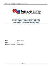
Power On (Amber)
LED Functions
Features DIP Switch Settings
OFF Ducted Indoor units
ON Ductless Indoor units
OFF HP control to maintain 42°C
ON HP control to maintain 50°C
OFF No De-Ice on start-up for 30 min.
ON Immediate De-Ice on start-up allowed.
OFF Outdoor fan low temp. cut off
ON Outdoor fan low temp. continuous
1
2
3
4
TZ.129 01/05
Other Functions / Indications
Outdoor Unit coil above 12°C. Terminates De-ice cycle.
Outdoor Unit coil below –4°C. May initiate De-ice cycle.
Suction (Discharge) service valve below –10°C.
Indoor coil icing protection. Stops compressor for 15 mins.
High Pressure fail
Low Pressure fail. Loss of refrigerant.
Suction (Discharge) service valve sensor fault
Head Pressure control sensor fault.
De-Ice sensor fault
Test Button
DIP switches
Fault Output (via auxillary relay board)
De-Ice Cycle operating (Green)
Outdoor Unit Controller (OUC)
LEDs when lit indicate:
Outdoor Fan operating (Green) Compressor
operating (Green)
(Red) (Amber)
(Red)
NOTE: Controller will shut down
this unit's operation after repeated
faults. Take note of 'fault' indication.
Power unit OFF, then ON to RESET.
(Factory standard settings
are to OFF position)
When power is switched on, LEDs on right side will flash in
a pattern from outside to centre and back for 15 seconds.
During this 3 min. cycle LEDs flash from bottom to top if signal
received on COMP terminal. (Compressor not allowed to run)
During this cycle LEDs flash from top to bottom if signal is
removed from COMP terminal. (Ensures compressor runs
no less than 3 mins)
In Heat cycle, press for 5 sec. to intiate a de-ice cycle – even
if 'Start' LED not lit. Resumes normal operation automatically.
In Heat cycle, press for 2 sec. to initiate a de-ice cycle if/when
'Start' LED lit. Resumes normal operation automatically.
System
Check
Anti Rapid
Cycle Timer
Running
Minimum
Run Timer
Running
Test
Button
Compressor Cycling Protection (3 mins)
Minimum Run Time (3 mins)
High Pressure Protection
Low Pressure Protection (if LP switch fitted)
Loss of Refrigerant Protection
Head Pressure Fan Speed Control
Indoor Coil Icing Protection
Outdoor Coil De-Icing (Heat Cycle)
Run & Fault LED Indication
Remote Common Fault Output
Repeat Fault Lockout Protection
Jumper (do not remove)
PCB Version
Release 2
temperzone ltd
LP Switch (if fitted)
connects here
Version
Program
In any state, press for 10 sec. to run Commissioning mode
(reduces some timers); resets automatically.
/