Page is loading ...

English
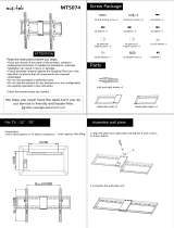
Motorized Full Motion LCD/Plasma Wall Mount - EU42SM
Installation Instructions
DO NOT RETURN THIS PRODUCT TO THE
STORE OR WEB SITE YOU PURCHASED IT
FROM!
IF YOU BELIEVE THIS MOUNT IS DEFECTIVE,
HAS MISSING OR BROKEN PARTS, OR IF
YOU ARE HAVING DIFFICULTY INSTALLING
THIS MOUNT TO YOUR WALL OR FITTING
YOUR TV, PLEASE CONTACT OUR COMPANY,
LEVEL MOUNT, DIRECTLY.
Dial +44 08700429781 or email us at
[email protected] any time of
the day or night for a quick and efficient solution
to your problem.
Our trained Customer Service Department is
open 24 hours a day, 7 days a week, every day
of the year and is prepared to assist you in both
English and Spanish.
Please also visit our Web Site at www.
LevelMount.com for assistance.
CAUTION:
Installer must make sure the LCD/Plasma
Wall Mount is properly and securely attached
and that appropriate fasteners are used. It is
the responsibility of the installer to verify that
the mount is anchored properly to the wall.
PLEASE NOTE: THE MOUNT MUST BE
ATTACHED TO WOOD STUDS OR TO
PROPERLY INSTALLED LEAD ANCHORS IN
MASONRY OR CONCRETE. DO NOT MOUNT
ONLY TO DRYWALL.
Before installing, check to make sure all parts
of the mount are included.
Make sure never to exceed the maximum
weight of 45 kg.
Make sure all screws and bolts are tightened
before allowing Wall Mount to bear the full
weight of the LCD/plasma display.
Mounting Hardware Included:
Bag Ref Description QTY
1
AM4X12/Bolts 4
BM4X20/Bolts 4
CM4X30/Bolts 4
DM4 Lock Washers 4
2
EM5X30/Bolts 4
FM5X12/Bolts 4
GM5X20/Bolts 4
HM5 Lock Washers 4
3
IM6X35/Bolts 4
JM6X24/Bolts 4
KM6X12/Bolts 4
LM6 Lock Washers 4
4
MM8x40 bolts 4
NM8X25/Bolts 4
OM8 Lock Washers 4
5
PM4/M5 Spacers 4
QM6/M8 Spacers 4
RWashersĭ20Xĭ5.5X1.2 4
6
SLag Bolts 3
TWashersĭ38Xĭ6.8X1.5 3
UHex wrench 1
VConcrete Anchor
ĭ12.5X44.5
3
Features:
• Integrated Bubble Level
• Durable Steel Construction
• Easy 2 Piece Mounting
• Tilts 15 degrees, Pans 30 degrees
• Locking Lever
• Stud Finder Included
AC
Adapter
SMM-08
Mount
LCD/Plasma
Mounting Arm
Remote
Control
Installation
Hardware
Stud Finder
Tools required for attachment to stud:
Hex Wrench (Included)•
Stud finder (Included)•
Electric drill•
4.7• mm Wood Drill Bit
Tools required for attaching to concrete:
Hex Wrench (Included)•
Electric drill •
1/2’’ (12mm) Masonry Bit•
www.LevelMount.com
+44 08700429781
©2008 Level Mount
Patents Pending
!
CAUTION
This wall mount was designed
speci¿ cally to hold LCD TV’s 10” - 42” and a
maximum weight of up to 45 kg. Using this
product with a TV heavier than the maximum
weight may result in injury.
CAUTION:
Installer must make sure the LCD/Plasma
Wall Mount is properly and securely attached
and that appropriate fasteners are used. It is
the responsibility of the installer to verify that
the mount is anchored properly to the wall.
PLEASE NOTE: THE MOUNT MUST BE
ATTACHED TO WOOD STUDS OR TO
PROPERLY INSTALLED LEAD ANCHORS IN
MASONRY OR CONCRETE. DO NOT MOUNT
ONLY TO DRYWALL.
Before installing, check to make sure all parts
of the mount are included.
Make sure never to exceed the maximum
weight of 45 kg.
Make sure all screws and bolts are tightened
before allowing Wall Mount to bear the full
weight of the LCD/plasma display.
Features:
• Integrated Bubble Level
• Durable Steel Construction
• Easy 2 Piece Mounting
• Tilts 15 degrees, Pans 30 degrees
• Locking Lever
• Stud Finder Included
®
D3012011bda.indd 1
D3012011bda.indd 1
09.10.2008 14:33:30 Uhr
09.10.2008 14:33:30 Uhr

Figure 1 Figure 2 Figure 3
Figure 4 Figure 5 Figure 6
Figure 7 Figure 8 Figure 9
Installation Instructions:
Attaching Wall Mount to Studs:
Locate a proper place to mount by using a quality stud finder 1.
(Figure 1). Mark center of stud. It is recommended that the
center of the stud be used and that a nail be used to verify that
a stud has been located.
Gently pull back vinyl cover at top of backplate to expose 2.
plate. Hold mount up to wall and mark wall at top of mount
backplate at desired height. (Figure 2) (Set mount aside after
marking)
Measure down stud from top of plate 66.6 mm and mark for 3.
first screw. (Figure 3) and drill (4.7 mm x 76 mm) deep pilot
hole into wall at mark
Using Hex Key (Provided) screw (1) Hex Screw into pilot hole 4.
leaving 3 mm gap to wall.
Carefully cut cable tie holding motorized plate. (Figure 9)5.
Place mount on screw using butterfly hole (second from top).6.
Level mount using Bubble Level and drill second (4.7 mm 7.
x 76 mm) deep pilot hole through bottom hole in backplate.
(Figure 7)
Using Hex Key attach 2nd screw/washer combination (Do Not 8.
Overtighten) (Figure 7)
Drill third (4.7 mm x 76 mm) deep pilot hole through hole 9.
through top hole in backplate. (Figure 8)
Attach third screw/washer combination (Do Not Overtighten)10.
Using Hex Key tighten first screw (Do Not Overtighten)11.
Attaching Wall Mount to Concrete:
Gently pull back vinyl cover at top of backplate to expose 1.
plate. Hold mount up to wall and mark wall at top of mount
backplate at desired height. (Figure 2) (Set mount aside after
marking)
Measure down from top of plate 66.6 mm and mark for first 2.
screw. (Figure 3)
Drill (12 mm x 83 mm) deep hole into wall at mark (Figure 4)3.
Insert Concrete Anchor flush with wall. (Figure 5)4.
Using Hex Key (Provided) screw (1) Hex Screw into concrete 5.
anchor leaving 3 mm gap to wall. (Figure 6)
Place mount on screw using butterfly hole (second from top).6.
Level mount using Bubble Level mark two remaining mounting 7.
holes on wall.
Remove mount and drill at marks (12 mm x 83 mm) deep 8.
holes.
Insert concrete anchors until flush with wall. (Figure 5)9.
Carefully cut cable tie holding motorized plate. (Figure 9)10.
Reinstall mount on single screw. 11.
Attach 2nd and 3rd screw/washer combination (Do Not 12.
Overtighten)
Using Hex Key tighten first screw (Do Not Overtighten)13.
Top of Mount
Top of Mount
Bottom of Mount
S
T
S
T
Top of Mount Mark
66.5 mm
Please Refer to Stud Finder
Instruction Manual
U
Attaching LCD/Plasma to Mounting Arms:
Determine Correct bolt to attach TV to Mounting Arm.1.
Caution: Carefully thread the bolt into the back
of your LCD to determine which bolt is to be used. If
there is any resistance remove the bolt immediately.
Select longest bolt that can be fully threaded into TV.
Never place LCD/Plasma screen face
down on any surface to prevent scratching.
DO NOT OVERTIGHTEN BOLTS WHEN INSTALLING ARMS
ON TELEVISION.
Install mounting arm to TV with Bolt, Lock Washer, and Flat 2.
Washer for M4 or M5 Bolts. (Figure 10)
Install mounting arm to TV with Bolt and Lock Washer3. for M6
or M8 Bolts. (Figure 11)
Figure 10
M4 and M5 Bolts
Bags 1 or 2
Figure 11
M6 and M8 Bolts
Bags 3 or 4
www.LevelMount.com
+44 08700429781
©2008 Level Mount
Patents Pending
(use spacer
Only if needed)
(use spacer
Only if needed)
®
D3012011bda.indd 2
D3012011bda.indd 2
09.10.2008 14:33:36 Uhr
09.10.2008 14:33:36 Uhr

Figure 12
Figure 13
Figure 14
Figure 15
Remote
Control
Attaching Mounting Arms to Wall Mount:
Place locking levers on mounting arm in horizontal position 1.
(Figure 12),
Slide arms with TV over mounting plate (Figure 13).2.
Rotate Locking Levers to vertical position (Figure 14) to 3.
secure TV to mount.
TV may be moved from left to right for final location.4.
Plug in AC power adapter to bottom of mount and wall outlet. 5.
(Figure 15)
Locking TV to Mount:
With locking lever in locked position, add padlock to prevent 1.
theft or accidental movement of lever. (Figure 16)
Figure 16
Using Cord Management:
Use Velcro strap at bottom of mount to secure all wires and 1.
cables. Make sure to leave enough wire above strap to allow
free movement of mount! (Figure 17)
Figure 17
Using Remote Control:
Press center button once to extend mount from wall1.
Adjust mount as desired.2.
Press center button again to return mount to seated position 3.
(mount will realign before moving back to wall)
Press top button to tilt mount up. (mount will
not tilt upward from parallel to wall)
Press bottom button to tilt mount down.
Press left button to pan mount left.
Press left button to pan mount right.
AAA x 3
Magnetic Holder
Back of Remote
Battery Cover
Note: Photos taken without TV
or mounting arms installed
Top View
Top View
Side View
Side View
Side View
www.LevelMount.com
+44 08700429781
©2008 Level Mount
Patents Pending
®
D3012011bda.indd 3
D3012011bda.indd 3
09.10.2008 14:33:39 Uhr
09.10.2008 14:33:39 Uhr
/