Page is loading ...

Ceiling Fan
Instruction Manual
by PCI
(Hugger Fans Only)

Table of Contents
QUESTIONS, PROBLEMS, MISSING PARTS:
Before returning to your local retailer, please call our
Customer Service Team at 1-877-706-3267.
Safety Rules . . . . . . . . . . . . . . . . . . . . . . . . . . . . . . . . . . . 1
Unpacking Your Fan . . . . . . . . . . . . . . . . . . . . . . . . . . . . 2
Installing Your Fan . . . . . . . . . . . . . . . . . . . . . . . . . . . . . 3
Hanging Your Fan . . . . . . . . . . . . . . . . . . . . . . . . . . . . . 4
Making the Electrical Connection . . . . . . . . . . . . . . . . 6
Finishing the Fan Installation . . . . . . . . . . . . . . . . . . . 7
Glass Installation . . . . . . . . . . . . . . . . . . . . . . . . . . . . . . 8
Balancing Your Fan . . . . . . . . . . . . . . . . . . . . . . . . . . . .11
Operating Your Fan . . . . . . . . . . . . . . . . . . . . . . . . . . . 12
Care of Your Fan / Troubleshooting . . . . . . . . . . . . .13
Specications . . . . . . . . . . . . . . . . . . . . . . . . . . . . . . . .14
Warranty Information . . . . . . . . . . . . . . . . . . . . . . . . .15
Assistance Hotline . . . . . . . . . . . . . . . . . . . . . . . . . . . . 16
80009 ∙ 06/23/11 ∙ PCI
Another Fine
Ceiling Fan
by PCI
ank you for purchasing this PCI ceiling fan. is
instruction manual will provide you with all the
information to install and operate your new ceiling fan.
is product has been fabricated with the highest
standards of quality and safety. Before Installing your
new ceiling fan, for your records, remember to record your
model number for warranty assistance. Please refer to
page 15 (warranty) for further details.

! !
WARNING
! !
WARNING
TO REDUCE THE RISK OF PERSONAL INJURY,
DO NOT BEND THE BLADE BRACKETS, WHEN
INSTALLING THE BRACKETS, BALANCING THE
BLADES OR CLEANING THE FAN. DO NOT INSERT
FOREIGN OBJECTS IN BETWEEN ROTATING FAN
BLADES.
TO REDUCE THE RISK OF FIRE, ELECTRIC SHOCK
OR PERSONAL INJURY, MOUNT FAN TO OUTLET
BOX MARKED ACCEPTABLE FOR FAN SUPPORT
WITH THE SCREWS PROVIDED WITH THE
OUTLET BOX.
1
Safety Rules - Read and Save ese Instructions
1. WARNING: To reduce the risk of electric shock, insure electricity has been
turned o at the circuit breaker or fuse box before beginning.
2. All wiring must be in accordance with the National Electrical Code “ANSI/
NFPA 70-1999” and local electrical codes. Electrical installation should be
performed by a qualied licensed electrician.
3. WARNING: To reduce the risk of electrical shock or re, do not use this fan
with any solid-state fan speed control device. It may cause permanent dam-
age to the motor and electronics.
4. CAUTION: To reduce the risk of personal injury, use only the screws pro-
vided with the outlet box.
5. e outlet box and support structure must be securely mounted and capable
of reliably supporting a minimum of 35 pounds. Use only CUL Listed outlet
boxes marked “FOR FAN SUPPORT.”
6. e fan must be mounted with a minimum of 7 feet clearance from the trail-
ing edge of the blades to the oor.
7. Avoid placing objects in path of the blades.
8. To avoid personal injury or damage to the fan and other items, be cautious
when working around or cleaning the fan.
9. Do not use water or detergents when cleaning the fan or fan blades. A dry
dust cloth or lightly dampened cloth will be suitable for most cleaning.
10. After making electrical connections, spliced conductors should be turned
upward and pushed carefully up into outlet box. Turn wire nut connections
upwards, spreading them apart so the green (grounded) wire will be on one
side of the outlet box and the white, black, and blue wires will be on the other
side, and push carefully up into the outlet box.
11. All set screws must be checked and retightened where necessary before
installation.
80009 ∙ 06/23/11 ∙ PCI

Standard Bowl EStar Bowl Globe Multi-Arm
The Fan you have purchased will be made up of one of the following light kit
congurations:
Please follow the instructions as they pertain to your specic componets.
Standard Bowl
Estar Bowl
Globe
Multi-Arm
1
4
5
6
7
8
10
11
9
2
1
13 13
13
15
13
15
15
2
3
4
14
14
14
14
15
16
17
18
12
! !
WARNING
DO NOT INSTALL OR USE FAN IF ANY PART IS
DAMAGED OR MISSING. CALL TOLL FREE
1-877-706-3267
2
Unpacking Your Fan
1. Set of blades (5)
2. Balancing kit
3. Blade Mounting
Hardware Kit
(not shown)
Optional Remote Control
16. Remote Transmitter
17. Remote Receiver
18. Remote Owner’s Manual
4. Owners Manual
5. Blade Brackets (5)
6. Canopy / Bracket Assembly
7. Ball / Downrod assembly (4” and 12”)
8. Pull Chain and Fob (2)
9. Fan Motor Assembly
10. Motor Housing
11. Cap and Finials in all Finishes
12. Switch Housing Cover
Loose parts bags containing (not shown):
Mounting hardware, blade attachment hardware, electrical
hardware, pull chains, wire connectors, etc.
13. Bowl
14. Fitter
15. 13W CFL Bulbs
(2)
13. EStar Bowl
14. Fitter
15. 13W GU24
CFL Bulbs
(2)
13. Globe
14. Fitter
15. 13W CFL
Bulb
13. 3 or 4 Pieces of
Side Glass
14. 13W CFL Bulbs
(3 or 4)
15. Multi Arm Fitter
Replacement Parts
1. Blades (5)
2. Blade Brackets (5)
3. Hardware Kit
4. Glass (3 Options)
80009 ∙ 06/23/11 ∙ PCI

Outlet Box
Outlet Box
Outlet Box
! !
WARNING
TO REDUCE THE RISK OF FIRE, ELECTRIC
SHOCK OR PERSONAL INJURY, MOUNT FAN
ONLY TO AN OUTLET BOX MARKED ACCEPTABLE
FOR FAN SUPPORT AND USE THE MOUNTING
SCREWS PROVIDED WITH THE OUTLET BOX.
OUTLET BOXES COMMONLY USED FOR THE
SUPPORT OF LIGHTING FIXTURES MAY NOT
BE ACCEPTABLE FOR FAN SUPPORT AND MAY
NEED TO BE REPLACED. CONSULT A QUALIFIED
ELECTRICIAN IF IN DOUBT.
3
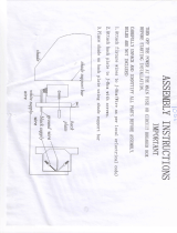
Installing Your FanInstalling Your Fan
Tools Required
Mounting Options
Phillips screwdriver, adjustable wrench, step
ladder, and wire cutters.
If there isn’t an existing mounting box, then
read the following instructions. Disconnect the
power by removing fuses or turning off circuit
breakers.
Secure the outlet box directly to the building
structure. Use appropriate fasteners and building
materials. The outlet box and its support
must be able to fully support the moving weight
of the fan (at least 35 lbs.) Do not use plastic
outlet boxes.
Figures 1-3 are examples of different ways to
mount the outlet box.
Figure 1
Figure 2
Figure 3
To hang your fan where there is an existing
xture but no ceiling joist, you may need an
installation hanger bar as shown in Figure 3
(available at your PCI Retailer).
80009 ∙ 06/23/11 ∙ PCI

Mounting
Screws
Washers
Mounting
Screw
Mounting
Bracket
Mounting
Bracket
“J” Hook
UL Listed
Electrical box
120V
Wires
Motor
Housing
Mounting
Bracket
! !
WARNING
TO REDUCE THE RISK OF FIRE, INSURE
ELECTRICITY HAS BEEN TURNED OFF AT THE
CIRCUIT BREAKER OR FUSE BOX BEFORE
BEGINNING.
4
Hanging Your Fan
Figure 6
Figure 4
Figure 5
Follow the steps below to hang your fan
properly.
1. Pass the 120-volt supply wires through
the center hole in the mounting bracket
(Figure 4).
2. Install the mounting bracket by raising the
mounting bracket to the UL listed electrical
box and securing with the 2 mounting screws
and washers (Figure 4).
3. Remove mounting crew that is preinstalled
on the motor bracket (Figure 5).
4. Carefully hang the motor assembly onto the
mounting bracket by inserting the “J” hook
into a slot on one side on the mounting bar
(Figure 6).
5. See “Making the Electrical Connection”
section for wiring the fan before continuing
to Step 6.
6. Lift motor assembly to mounting bracket.
Align holes and secure motor assembly with
nuts previously saved (Figure 7).
Figure 7
80009 ∙ 06/23/11 ∙ PCI

Mounting
Screws
Mounting
Screws
L-Slots
Mounting
Bracket
Mounting
Bracket
Washers
Washers
5
Hanging Your Fan
Figure 8
Figure 9
7. There are 4 housing mounting screws
preinstalled on the periphery of the mounting
bracket. Remove one pair of the screws and
washers which match the round holes of
the motor housing opposite each other, and
loosen the remaining 2 screws and washers
that are also opposite one another. Make sure
the washer is pushed toward the screw head
of each loosened screw (Figure 8).
8. Attach the motor housing to the mounting
bracket by aligning the 2 loosened screws
preinstalled on the mounting bracket into the
2 L-slots of the motor housing. Then turn the
housing clockwise so that the screws more
towards the end of the L-slots. The housing
should now sit securely on the screws. Then
insert the two housing mounting screws
preinstalled to secure the motor housing
(Figure 9).
NOTE: Make sure the washers are in between
the housing and the screw heads.
80009 ∙ 06/23/11 ∙ PCI

SUPPLY CIRCUIT
BLACK
WHITE
BLACK
BLUE
GREEN
WHITE
Ground
Conductor
Outlet Box
Green
Ground
Lead
Ground to
Downrod
Switch
Motor
Housing
Motor Housing
! !
WARNING
! !
WARNING
ELECTRICAL DIAGRAMS ARE FOR REFERENCE
ONLY. OPTIONAL USE OF ANY LIGHT KIT SHALL
BE UL LISTED AND MARKED SUITABLE FOR USE
WITH THIS FAN.
CHECK TO SEE THAT ALL CONNECTIONS ARE
TIGHT, INCLUDING GROUND, AND THAT NO
BARE WIRE IS VISIBLE AT THE WIRE NUTS,
EXCEPT FOR THE GROUND WIRE.
! !
WARNING
TO REDUCE THE RISK OF SHOCK, INSURE
ELECTRICITY HAS BEEN TURNED OFF AT THE
CIRCUIT BREAKER OR FUSE BOX BEFORE
BEGINNING.
6
Making e Electrical Connection
Figure 10
If you feel you do not have enough electrical
wiring knowledge or experience, have your fan
installed by a licensed electrician.
Follow the steps below to connect the fan to
your household wiring. Use the wire connecting
nuts supplied with your fan. Secure the
connectors with electrical tape. Make sure there
are no loose strands or connections.
1. Connect the ground conductor of the 120v
supply (this may be a bare wire or a wire with
green colored insulation) to the green ground
lead(s) of the fan (Figure 10). When using
“closeto-ceiling” mounting, there is only one
green ground lead from the ceiling mounting
bracket since the ball/downrod assembly is
not used.
2. Connect the fan motor white wire to the
supply white (neutral) wire using a wire nut
(Figure 10).
3. Connect the fan motor black wire to the
supply black (hot) wire using a wire nut
(Figure 10).
4. Connect the blue wire for the light kit to the
black household supply wire.
5. Turn wire nut connections upwards, spreading
them apart so the green (grounded) wire will
be on one side of the outlet box and the white,
black, and blue wires will be on the other
side, and push carefully up into the outlet box.
80009 ∙ 06/23/11 ∙ PCI

Screws
Blade Bracket
Blade Bracket
Screw
Paper Washer
Blade
Washers
! !
WARNING
MOTOR IS SHIPPED WITH RUBBER MOTOR
BLOCKS TO PREVENT MOVEMENT DURING
TRANSPORTATION. REMOVE MOTOR BLOCKS
PRIOR TO ATTACHING BLADE BRACKETS.
7
Finishing e Fan Installation
Figure 11
Figure 12
Attaching the Fan Blades
2. Tighten each screw securely.
3. Fasten the blade assembly to the motor by
inserting the alignment post into the slot on
the bottom of the motor and tightening the
motor screws. Please note that the motor
screws may be pre-attached into the blade
brackets (Figure 12).
4. Repeat steps 1-3 for the remaining blades.
1. Attach blade to blade bracket using the screws
provided (Figure 11). Insert a screw into the
bracket. Repeat for the two remaining screws.
1. Carefully unhook the fan from the mounting
plate and align the locking slots of the canopy
with the two screws in the mounting plate.
Push up to engage slots and turn clockwise
to lock in place. Immediately tighten the two
mounting screws rmly.
2. Install the remaining two mounting screws
into the holes in the canopy and tighten rmly.
3. You may now proceed to attaching the fan
blades.
Close-to-Ceiling Mounting
80009 ∙ 06/23/11 ∙ PCI

Switch Housing
Screws
Thumbscrews
Blue Wires
White Wires
Bulb
Light Kit
Globe
Fan with light kit
8
Glass Installation Options 1
Figure 13
Figure 14
1. Connect the two blue to blue light kit wires by
single pin and connect the two white to white
light kit wires by single pin.
2. Remove the three screws from the switch
housing, then insert the light kit into the
switch housing.
3. Align the three screw holes in the switch
housing with the screw holes in the light kit.
4. Re-Install the three screws.
5. Install bulb provided.
6. Insert the globe into the xture. Tighten the
thumbscrews manually until nger-tight. Do
not overtighten.
Note: If thumbscrews are pre-installed, loosen
the thumbscrews before inserting the globe,
then retighten securely.
Your Fan will have one of the following 3 light
kit options: Globe, Bowl, or Multi-Arm Light
Kit.
Option 1
Attaching the Globe
1. Only the fan pull chain is functional. Second
light pull chain in switch housing does not
function for this conguration but must
be in the “on” position for proper light kit
operation.
2. Refer to the instructions that came with your
accessory light kit for proper assembly.
3. Consult a certied electrician if needed.
Aftermarket Option
Accessory Light Kit
for fans without light kits
80009 ∙ 06/23/11 ∙ PCI

Screws
Pull Chains
Switch Housing
Bulbs
Glass
Shade
(Bowl)
Glass Cap
Decorative Nut
Metal Washer
Rubber Washer
Hex Nut
Wire Connectors
Light Kit
Assembly
Metal Stem
Switch Housing
Screws
Switch Housing
Cover
NOTE
NOTE
BEFORE STARTING INSTALLATION,
DISCONNECT THE POWER BY TURNING OFF
THE CIRCUIT BREAKER OR REMOVING THE
FUSE AT FUSE BOX. TURNING POWER OFF
USING THE FAN SWITCH IS NOT SUFFICIENT TO
PREVENT ELECTRIC SHOCK.
MAKE SURE TO LEAVE ENOUGH SPACE
BETWEEN THE FAN PULL CHAIN AND THE
BULBS SO THE CHAIN DOESN’T RUB AGAINST
ANY OF THE BULBS.
NOTE
LIGHT BULBS HAVE NO WARRANTY; CAN BE
PURCHASED AT ANY HOME RETAILER.
NOTE
YOUR FAN MAY HAVE A 4 PIN CONNECTOR THAT
WILL BE USED IN PLACE OF THE WHITE AND
BLUE WIRE CONNECTORS.
9
Option 2
Installing the
Bowl Light Kit
1. Unscrew the hex nut from the top of the light
socket and insert light socket through the hole
in the bottom center of the switch housing, then
reassemble the hex nut to the light socket securing
the two pieces rmly together.
2. While holding the light kit assembly under your
fan, locate two single white and blue wires in the
switch housing labeled FOR LIGHT. Make the
polarized plug connections:
- White to white
- Blue to black
3. Carefully push all wires back into the switch
housing. Attach the light kit tter by aligning its
keyhole slots with the three screws holes and
reversing switch on the side of switch housing.
Tighten the three screws securely to prevent the
light kit from vibrating loose. (Fig. 15)
Your fan is designed with light kit, in case you
intend to install the fan without light kit, attach
the switch housing cover to the switch housing
with the screws provided. (Fig. 16)
Fan without Bowl Light Kit
(Optional)
4. Install bulbs (included).
5. Place the glass shade over the light kit stem. While
holding the shade in place, position the glass cap
over the threaded stem and secure entire assembly
with the decorative nut. Do not overtighten.
6. Feed the pull chain(s) through the eyelet in the
shade and cap. Secure the light kit assembly with
decorative nut provided. Do not overtighten.
(Fig. 15)
Figure 15
Figure 16
Glass Installation Options 2
80009 ∙ 06/23/11 ∙ PCI

Screws
Light kit
Reverse
Switch
4 Pin Connector
(or 4 pin connector)
Switch Housing
Thumb
Screws
Bulbs
Glass Shade
NOTE
YOUR FAN MAY HAVE A 4 PIN CONNECTOR THAT
WILL BE USED IN PLACE OF THE WHITE AND
BLUE WIRE CONNECTORS
! !
CAUTION
BEFORE STARTING INSTALLATION,
DISCONNECT THE POWER BY TURNING OFF
THE CIRCUIT BREAKER OR REMOVING THE
FUSE AT FUSE BOX. TURNING POWER OFF
USING THE FAN SWITCH IS NOT SUFFICIENT TO
PREVENT ELECTRIC SHOCK.
NOTE
THE LIGHT KIT WITH YOUR FAN MAY HAVE 3
OR 4 LIGHTS
10
Glass Installation Options 3
Figure 17
Figure 18
Option 3
Installing the
Multi Arm Light Kit
1. While holding the light kit assembly under
your fan, locate two single white and blue
wires in the switch housing labeled FOR
LIGHT. Make the polarized plug connections:
- White to white
- Blue to black
2. Carefully push all wires back into the switch
housing. Attach the light kit tter by aligning
its keyhole slots with the three screw holes
and the reverse switch on the side of the
switch housing. Tighten the three screws
securely to prevent the light kit from vibrating
loose. (Fig. 17)
3. Mount the glass shades to the light xture
by unscrewing partway the thumbscrews on
the glass holders, insert the glass, then gently
tighten the thumbscrews by hand evenly to
the glass. DO NOT OVER TIGHTEN
(Fig. 18).
4. Install three bulbs (included). NOTE: CFL
bulbs are NOT dimmable.
80009 ∙ 06/23/11 ∙ PCI

Touching
Ceiling
Adhesive
Weight
Blade
Clip-On
Weight
11
Balancing Your Fan
The following procedure should correct most fan wobble.
Check after each step.
1. Check that all blade and blade bracket screws are secure.
2. Most fan wobble problems are caused when blade levels are unequal. Check this level
by selecting a point on the ceiling above the tip of one of the blades. Measure from a
point on the tip of each blade to a point directly above the blade on the ceiling. Measure
this distance as shown in Figure 19. Rotate the fan until the next blade is positioned for
measurement. Repeat for each blade. Measurements deviation should be within 1/8”. Run
the fan for 10 Minutes.
3. Use the enclosed Blade Balancing Kit if the blade wobble is still noticeable.
4. To use the kit, begin by adjusting the fan speed to nd where you get the most wobble.
5. Turn off the fan and then attach the clip-on weight about halfway down any blade.
6. Turn the fan back on to see if this has helped the wobble, continue moving the clip-on
weight from blade to blade.
7. Once you have isolated the “wobble” blade, start moving the clip-on weight up and down
the length of the blade (starting and stopping the fan each time) until you locate the correct
spot to stop the wobble.
8. Once the wobble has been located, place one of the adhesive weight on the upper side of
the blade where the clip-on weight was located.
9. Remove the clip-on weight, turn the fan on.
Figure 19
Figure 20
80009 ∙ 06/23/11 ∙ PCI

NOTE
WAIT FOR FAN TO STOP BEFORE CHANGING
THE SETTING OF THE SLIDE SWITCH.
12
Operating Your Fan
Turn on the power and check the operation of your fan. There are
two pull chains available in your fan:
1. 3-speed pull chain- it controls the fan speed as follows:
1-Pull = High Speed
2-Pulls = Medium Speed
3-Pulls = Low Speed
4-Pulls = Fan Off
Speed settings for warm or cool weather depend on factors such as
the room size, ceiling height, number of fans, and so on.
Cool weather - (Reverse) An upward airow moves warm air off
the ceiling area as shown in Figure 22. This allows you to set your
heating unit on a lower setting without affecting your comfort.
The slide switch controls directions: forward (switch down ) or
reverse (switch up ).
Warm weather - (Forward) A downward air ow creates a cooling
effect as shown in Figure 21. This allows you to set your air
conditioner on a higher setting without affecting your comfort.
Figure 21 Figure 22
80009 ∙ 06/23/11 ∙ PCI

! !
WARNING
MAKE SURE THE POWER IS OFF AT THE ELECTRICAL PANEL
BOX BEFORE YOU ATTEMPT ANY REPAIRS. REFER TO THE
SECTION, “MAKING ELECTRICAL CONNECTIONS.”
13
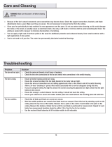
Care Of Your Fan / Troubleshooting
Care of Your Fan Troubleshooting
PROBLEM SOLUTION
Here are some suggestions to help you
maintain your fan.
1. Because of the fan’s natural movement,
some connections may become loose.
Check the support connections, brackets,
and blade attachments twice a year. Make
sure they are secure. (It is not necessary
to remove fan from ceiling.)
2. Clean your fan periodically to help
maintain its new appearance over the
years. Do not use water when cleaning.
Use only a soft brush or lint-free cloth to
avoid scratching the nish. The plating
is sealed with a lacquer to minimize
discoloration or tarnishing.
3. You can apply a light coat of furniture
polish to the wood for additional
protection and enhanced beauty. Cover
small scratches with a light application of
shoe polish.
4. There is no need to oil your fan. The
motor has permanently lubricated sealed
ball bearings.
1. Check main and branch circuit fuses or breakers.
2. Check line wire connections to the fan and switch wire
connections in the switch housing.
1. Make sure all motor housing screws are snug.
2. Make sure the screws that attach the fan blades bracket to the
motor hub are tight.
3. Make sure wire nut connections are not rattling against each
other or the interior wall of the switch housing.
CAUTION: Make sure main power is off.
4. Allow a 24-hour “breaking-in” period. Most noises associated
with a new fan disappear during this time.
5. If using the ceiling fan light kit, make sure the screws securing
the glassware are tight. Check that the light bulb is also secure.
6. Make sure there is a short distance from the ceiling to the
canopy. It should not touch the ceiling.
7. Make sure your ceiling box is secure and rubber isolator pads
are used between mounting bracket and outlet box.
Fan will not start
Fan sounds noisy
80009 ∙ 06/23/11 ∙ PCI

Typical Measurements for This Fan Series.
NOTE
THE VALUES ON THIS CHART ARE APPROXIMATE AND REPRESENTATIVE OF
THE PERFORMANCE OF TYPICAL FANS WITH THE SAME SIZE MOTOR, BLADE
DIAMETERS AND PITCH AS THE FAN YOU PURCHASED. THESE MEASUREMENTS
DO NOT INCLUDE ANY POWER THAT THE LIGHT KIT USES. FOR PRECISE
SPECIFICATIONS PLEASE REFER TO THE CHART ON THE CARTON.
14
Specications
These are approximate measures. They do not include Amps and Wattage used by the light kit.
Fan Size Speed Volts Amps Watts RPM CFM CFM/W
52”
(1.32 m)
Low 120 0.21 78 188 2988 38
Medium 120 0.34 30 125 1254 42
High 120 0.50 17 88 995 58
80009 ∙ 06/23/11 ∙ PCI

15
Warranty
IMPORTANT NOTE:
To ensure warranty service, your fan must be
registered (see warranty card herein)
You must present a copy of the original
purchase receipt to obtain warranty service.
CEILING FAN WARRANTY CENTER
3059 FOREST HILL IRENE RD., SUITE 103
GERMANTOWN, TN 38138
Attach receipt here for
easy location.
80009 ∙ 06/23/11 ∙ PCI
PCI Lifetime Limited Warranty
(Lifetime warranty on motor)
PCI warrants the fan motor to be free from defects in workmanship and material present at time of shipment from
the factory for a lifetime after the date of purchase by the original purchaser. PCI also warrants that all other fan
parts, excluding any glass or acrylic blades, to be free from defects in workmanship and material at the time of
shipment from the factory for a period of one years after the date of purchase by the original purchaser. We agree
to correct such defects without charge or at our option replace with a comparable or superior model if the product
is returned to PCI. To obtain warranty service, you must present a copy of the receipt as proof of purchase. All
costs of removing and reinstalling the product are your responsibility. Damage to any part such as by accident
or misuse or improper installation or by afxing any accessories, is not covered by this warranty. Because
of varying climatic conditions, this warranty does not cover any changes in plated nishes, including rusting,
pitting, corroding, tarnishing or peeling. Brass nishes of this type give their longest useful life when protected
from varying weather conditions. A certain amount of “wobble” is normal and should not be considered a defect.
Servicing performed by unauthorized persons shall render the warranty invalid. To obtain service, contact our
service department at 1-877-706-3267. You will be responsible for all insurance and freight charges. A copy
of the sales receipt is required to obtain service. We will return you fan freight pre-paid. Please pack your fan
properly to avoid damage in transit. PCI will not be responsible for such damages.
In no event shall PCI be liable for consequential or incidental damages.
Some states do not allow the exclusion or limitation of consequential or incidental damages, in which case the
above limitation or exclusion may not apply.
This warranty gives you specic legal rights. You may also have other rights which vary state to state.

16
Owner Registration Card
80009 ∙ 06/23/11 ∙ PCI
Owner Registration Card
Please ll out, cut along dashed line, afx proper postage and return the owner
registration card within 10 days to insure that your new Ceiling Fan is covered by the
limited warranty.
Purchaser’s Name:
Address:
State:
Zip:
Model No:
Purchase Date:
Where Purchased (Store Name):
Store Address:
State:
Zip:
Type of store where purchased:
If home installation, which room?
Where fan will be used:
If commercial Institution, what type of business?
Lighting Center
Building Supply Center
Department Store
Family Room
Patio
Living Room
Restaurant
Bar
Store
Ofce
Other
Bedroom
Porch
Kitchen
Other
Other
Vendor No:
UPC:

17
Assistance Hotline
80009 ∙ 06/23/11 ∙ PCI
CALL TOLL-FREE
FOR ASSISTANCE
WE PROVIDE
Prompt shipment of missing, broken, or
defective parts.
CALL 1-877-706-3267
Between 8:00 am and 5:00 pm
PacicStandardTime,Monday-Friday
Glass Broken
Missing Parts?
?
NEED HELP?
PleaseDONOTRETURNMERCHANDISE
BEFOREYOUCALL
/