READ AND SAVE THESE INSTRUCTIONS
Installation Instructions* for
High-Capacity Steam Humidiers
(Models HSP2000 and HSP2600)
Also includes:
Programmable Flushing Timer
Installation Instructions
Operating and Maintenance Instructions
CONTRACTOR: Read these instructions before install-
ing or servicing humidier
HOMEOWNER: Save this manual for future reference.
*See “Wiring Instructions for High-Capacity Steam Humidiers” separately
Model No:
Mfg. Date (see label on unit):
Installation Date:

2
3
Table of Contents
Page
CONTRACTOR:
How To Install a White-Rodgers ComfortPlus Steam Humidier ................. 3
Safety Precautions ................................................................................ 3
Tools & Materials Needed ..................................................................... 4
Selecting a Location .................................................................................... 4
Mounting the Humidier (Options A-C) ........................................................ 5
Plumbing and Setting the Water Level ........................................................ 8
How To Install the Programmable Automatic Flushing Timer .................... 10
To Reprogram the Automatic Flushing Timer .......................................11
How to Maintain a White-Rodgers Steam Humidier ................................ 12
Troubleshooting ......................................................................................... 14
Replacement Parts .................................................................................... 15
HOMEOWNER:
How Your Humidier Works ....................................................................... 17
How To Extend the Life of Your Humidier ................................................ 18
FAQs about IAQ ........................................................................................ 19
Contact Information ............................................................. 20 (Back Cover)
•
•
•
For the Contractor:
How To Install a White-Rodgers
ComfortPlus Steam Humidier
NOTES: This humidier must be installed by a qualied professional
contractor. Failure to comply with this requirement may nullify the
warranty.
Read all instructions before beginning installation of the humidier.
White-Rodgers assumes no responsibility under warranty if the contractor
and/or user do not follow these printed instructions.
FOR WIRING INSTRUCTIONS AND INSTALLATION OF THE ELEC-
TRONIC COMPENSATING HUMIDISTAT, PLEASE SEE SEPARATE
INSTRUCTIONS ENCLOSED IN THE HUMIDIFIER CARTON.
Safety Precautions
Do not install a humidier where the surrounding temperature may
exceed 200ºF.
CAUTION: Excessive heat will damage the humidier, possibly causing
an overow condition and water damage to the home.
Do not install a humidier where the surrounding temperature may be
32ºF or colder (e.g., attics, garages, etc.).
CAUTION: Freezing water will damage the humidier and burst the
supply pipe, resulting in damage to the home.
Do not cut or drill into any air conditioning components or electrical
enclosures during humidier installation.
DANGER: Electrocution is possible if you come in contact with a
live electrical wire. Blindness can occur if refrigerant contacts your
eyes.
When the humidier is installed in a nished basement or any area
where water damage could occur, be sure to connect the humidier’s
overow provision to a suitable drain.
For above-ceiling installations, install an additional drain pan plumbed
to a suitable drain.
Installation, wiring and plumbing of the humidier must comply with local
codes, ordinances and regulations.
1.
2.
3.
4.
5.
6.

4
5
Tools and Materials Needed
Safety glasses
Tin snips or aviation snips
Electric drill
3/8" and 7/64" drill bits
Pliers
Screwdrivers (medium at point and Phillips #1)
Level
Hammer
Small adjustable wrench
Center punch
Knife
Wire and hardware to connect fan control
Additional relay(s)
For some installations:
Duct tape
1/4" copper water line
Tubing and ttings for the overow connection
2 conductor low-voltage wire
Selecting a Location
For most installations, mount the humidier under the horizontal warm
air supply duct. As an alternative, the unit can be mounted on a verti-
cal plenum using a fabricated transition for support. (See “Mounting the
Humidier”, pages 5-7.)
NOTE: Ideally the White-Rodgers ComfortPlus Steam Humidier is not
intended for installation in or on the return air duct or plenum. However,
some contractors do so without complications. If you choose to install
a ComfortPlus Steam Humidier under a return air duct or on
a return air plenum, be aware that moisture MUST be absorbed
BEFORE entering the lter, blower, turn or transition. Therefore,
INSTALL THE HUMIDIFIER AT LEAST 4-TO-6 FEET PRIOR TO
THESE DEVICES AND CONFIGURATIONS.
Select a location where the humidier can be plugged in without the
use of an extension cord. (See separate manual, “Wiring Instructions for
High-Capacity Steam Humidiers”.)
Select a location that will not allow steam to condense on the system air
mover, electrical components, etc.
Mount the unit on rigid metal ductwork, never on duct board or internally-
insulated duct.
1.
2.
3.
4.
5.
6.
7.
8.
9.
10.
11.
12.
13.
14.
15.
16.
17.
1.
2.
3.
4.
CAUTION: For all installation congurations, the mounting area
must be strong enough to support the humidier’s weight when
it is full of water (approximately 18 lbs.), and to hold the humidier in
a level position for safe, reliable operation. Otherwise, additional duct
reinforcement will be necessary.
NOTE: If the installation includes exposed insulated materials, a sec-
tion of the ductwork must be removed and replaced with rigid metal duct
extending at least 6 feet downstream from the humidier.
Mount the unit at least 4-to-6 feet after the plenum transition. Avoid sud-
den turns or transitions in the ductwork in the immediate area down-
stream from the humidier.
5.
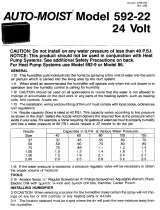
To install Option A:
Place the mounting bracket (provided)
on the edge of the ductwork where the
humidier is to be installed.
Use a marker to trace around the in-
side of the mounting bracket. Cut out
the duct opening.
CAUTION: DO NOT attach the
mounting bracket before the hole in
the ductwork has been cut.
1.
2.
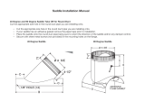
Mounting the Humidier
Option A is the preferred method of
mounting because it requires the least
amount or duct reinforcement to support
the humidier and keep it level. A duct
width of at least 10 inches is necessary.
Wider ducts may need to be reinforced in
order to hold the humidier level.
DANGER: Wear safety glasses when
cutting or drilling. Do not cut or drill
into any air conditioning components or
electrical enclosures during installation.
Electrocution is possible if you come
in contact with a live electrical wire;
blindness can occur if refrigerant con-
tacts your eyes.
Attach the mounting bracket to the ductwork with sheet metal screws.
Attach the L-shaped bracket to the top/front of the humidier, so that the
vertical wall is toward the reservoir.
3.
4.
Figure 1—Option A:
Duct Edge Mount
Figure 2—Mounting Bracket

6
7
Adjust the water level. (See Nos. 7 & 8 in “Plumbing and Setting the
Water Level”, pages 8 & 9.)
Slide the anges of the humidier reservoir into the mounting bracket until
the reservoir’s front ange comes in contact with the edge of the duct.
Secure the humidier to the duct with the screws provided.
Option B requires a transition to be
made, and usually needs duct reinforce-
ment to hold the humidier securely in
place.
NOTE: For this conguration, the humidi-
er is mounted on the outside of the ple-
num, rather than the inside, so as not to
restrict airow.
DANGER: Wear safety glasses when
cutting or drilling. Do not cut or drill
into any air conditioning components or
electrical enclosures during installation.
Electrocution is possible if you come
in contact with a live electrical wire;
blindness can occur if refrigerant con-
tacts your eyes.
To install Option B:
5.
6.
7.
Option C requires duct reinforcement
to hold the humidier securely in place.
DANGER: Wear safety glasses when
cutting or drilling. Do not cut or drill
into any air conditioning components or
electrical enclosures during installation.
Electrocution is possible if you come
in contact with a live electrical wire;
blindness can occur if refrigerant con-
tacts your eyes.
To install Option C:
Place the mounting bracket (provided)
at the selected location on the bottom
of the duct.
Use a marker to trace around the in-
side of the mounting bracket. Cut out
the duct opening.
CAUTION: DO NOT attach the
mounting bracket before the hole in
the ductwork has been cut.
Attach the mounting bracket to the
ductwork with sheet metal screws.
Adjust the water level. (See Nos. 7 &
8 in “Plumbing and Setting the Water
Level”, pages 8 & 9.)
1.
2.
3.
4.
Slide the anges of the humidier reservoir into the mounting bracket.
Secure the humidier to the duct with the screws provided.
NOTE: See separate wiring instruction manual, “Wiring Instructions
for High-Capacity Steam Humidiers”.
5.
6.
Construct a transition and attach it
to the plenum. (Additional humidier
support will be necessary for this
conguration.)
Place the mounting bracket (provided)
at the base of the transition.
Use a marker to trace around the
inside of the mounting bracket. Cut
out the duct opening.
CAUTION: DO NOT attach the
mounting bracket before the hole in
the ductwork has been cut.
1.
2.
3.
Attach the L-shaped bracket to the top/front of the humidier so that the
vertical wall is toward the reservoir.
Adjust the water level. (See Nos. 7 & 8 in “Plumbing and Setting the
Water Level”, pages 8 & 9.)
Slide the anges of the humidier reservoir into the mounting bracket.
Secure the humidier to the duct with the screws provided.
4.
5.
6.
7.
Figure 4—Mounting Bracket
Figure 6—Mounting Bracket
Figure 3—Option B:
External Side Mount
Figure 5—Option C:
Duct Center Mount

8
9
Plumbing and Setting the Water Level
NOTE: Use copper tubing only to plumb the humidier.
Select the nearest cold water pipe and install the saddle connector and
needle valve (provided) by following the instructions supplied with the
valve.
WARNING: Do not use any line connected to an air conditioner.
Lightly clean the tubing ends with ne sandpaper before making con-
nections.
1.
2.
Uncoil the copper tubing and
connect one end to the saddle
valve. Use the compression
ttings found in the self-
piercing saddle valve parts
bag.
Place the brass compres-
sion nut over the tubing,
then slide the brass ferrule
over the tubing.
Fully insert the tubing into
the saddle valve tting
and tighten the compres-
sion nut. (Do not over-tighten; moderate tightness should prevent
leakage.)
Thoroughly ush the supply tubing after attaching it to the saddle
valve. This will clear the line of debris which could block water ow
at the oat valve.
Route the tubing to the humidier oat valve, keeping the tubing away
from sharp edges.
Connect the remaining end of the tubing to the humidier oat valve.
Open the saddle valve so that the water ows slowly and gently into the
water pan.
Prior to mounting, adjust the humidier’s water level by following these
instructions:
Set the humidier reservoir on a level surface.
Allow the unit to ll until the oat valve shuts off the incoming ow of
water. (The water should be 2-3/8" deep, plus or minus 1/8". If it is
not, further adjustment will be necessary.)
3.
•
•
•
4.
5.
6.
7.
•
•
Figure 7—Saddle Valve and Fittings
If the water level is too high, remove enough water from the reservoir to
allow the oat valve to automatically ll and shut off the water. This will
verify that your nal adjustment is correct.
Shut off the water supply and remove all water from the reservoir.
Mount the humidier according to Options A, B or C, shown on pages
5-7.
Check the two compression ttings—one at the saddle valve, the other at
the oat valve. Stop any leakage by tightening the ttings.
Connect the humidier’s overow provision to a suitable waste drain.
A standard garden hose or a 3/8" N.P.T. male tting (not supplied)
can be attached to the overow tting.
Provide support at many points along the hose to prevent kinks—
particularly near any heat source.
Turn the water to the humidier on. The oat valve should shut the water
off when the pan is lled to 2-3/8".
Make sure the humidier is plugged into a powered outlet.
Adjust the compensating humidistat according to instructions provided
with the unit.
8.
9.
10.
11.
12.
•
•
13.
14.
15.
CAUTION: To prevent valve seat damage, never adjust the humidi-
fier’s water level without supporting the float arm. Make adjustments
in small increments.
To raise the water level, push down in the center of the oat arm.
(See Figure 8-A, below.)
To lower the water level, hold the oat on the bottom of the reservoir
with one hand and pull up on the center of the oat arm with the other
hand. (See Figure 8-B, below.)
•
•
Figure 8-A—Raising the
water level
Figure 8-B—Lowering the
water level

10
11
The Humidier Automatic Flushing Timer
automatically ushes accumulated min-
eral deposits from all central-system
steam- and reservoir-type humidiers.
This enables homeowners to enjoy the
benets of healthful, humidied air without
the hassles of frequent maintenance due
to mineral buildup.
The ushing timer is set at the factory
to ush the humidier every two hours
for a duration of 10 seconds, using
only about 1.5 gallons of water per day.
(See “To Reprogram the Automatic Flushing Timer”, pages 11 and 12, for
alternate settings.) This ushing reduces or eliminates servicing during the
humidication season, depending on the mineral content of the water.
How To Install the
Pro grammable Automatic Flushing Timer
To Install the Flushing Timer on a Steam Humidier:
Locate a suitable waste drain for disposal of ushed water.
CAUTION: Drain tubing must not kink or come in contact with
sharp edges or hot surfaces. Tubing must run in a continual down-
hill slope to allow proper drainage and to prevent overow.
4a. If this ushing timer was purchased as an accessory to install on a
steam humidier... remove the drain valve from the humidier and
install the 90º barbed tting (provided). (See Figure 9 on page 10.)
4b. If this ushing timer was purchased with the steam humidier as a
complete assembly... the 90º barbed tting should already be installed
on the humidier in the proper location. (See Figure 9 on page 10.)
Screw the unit to the mounting surface selected in Step #2.
Cut a piece of drain tubing to reach from the humidier tting to the tting
on the side of the ushing timer.
CAUTION: Drain tubing must not kink or come in contact with sharp
edges or hot surfaces. (This caution applies to step #7, as well.)
Cut a second piece of tubing to reach from the bottom tting on the
ushing timer to the drain. (See Step #3.)
Connect tubing with clamps or ttings suitable for your installation.
Return the steam humidier to its normal operating mode. Refer to pages
8 & 9 to properly set the water level.
Plug the ushing timer into the designated outlet. (See Step #2.)
Check all ttings for leaks. Tighten as necessary.
Test the ushing timer for proper operation.
Press and release the MANUAL button.
Wait 10 to 30 seconds* until the ushing noise stops, indicating that
the ushing cycle is complete.
*The number of seconds will vary depending upon how the unit is
programmed. (See “To Reprogram the Automatic Flushing Timer”,
below.)
To Reprogram the Automatic Flushing Timer:
The ushing timer is set at the factory to ush the humidier every two hours
for a duration of 10 seconds, using approximately 1.5 gallons of water per
day. Although the two-hour intervals between ushes may not be altered, the
duration may be lengthened to either 20 or 30 seconds per ush.
Unplug the ushing timer from the electrical outlet.
Take off the back cover plate by removing the three screws closest to
the mounting anges.
3.
5.
6.
7.
8.
9.
10.
11.
12.
A.
B.
1.
2.
Figure 9—Installation of a
Programmable Automatic
Flushing Timer on a Steam
Humidier
CAUTION: All plumb-
ing and electrical con-
nections must comply
with relevant codes and
ordinances.
If the humidier has
been preinstalled and
needs servicing, refer
to “How to Maintain a
White-Rodgers Com-
fortPlus Humidier”
(page 12) for instructions.
For either a new or preinstalled humidier, select a suitable mounting
locations for the ushing timer within 3 feet of the humidier, and within
10 feet of a properly fused electrical outlet.
1.
2.

12
13
Inside, on the circuit board, locate the red switch block which contains
two switches, numbered 1 and 2.
NOTE: The switches are pre-set in the 10-second mode,
with the #1 switch in the ON position and the #2 switch in the
OFF position, as shown at right. (Both switches in the ON
position will also produce a 10-second ush.)
To reprogram the ushing timer to 20-second ushes every
2 hours, move the #1 switch to the OFF position and the #2
switch to the ON position, as shown at left. At this setting,
the automatic ushing timer will use approximately 3 gallons
of water per day.
To reprogram the ushing timer to 30-second ushes every
2 hours, move both switches to the OFF position, as shown
at right. At this setting, the automatic ushing timer will use
approximately 4.5 gallons of water per day.
Reposition the back cover plate on the ushing timer and
secure it with the three screws.
Plug the ushing timer back into the wall outlet. Make sure it is function-
ing properly with the humidier (see Step #12, page 11).
NOTE: Lengthening the ushing duration will help keep the humidier
cleaner. However, it may also cause undesirable drain noise.
How to Maintain a White-Rodgers
ComfortPlus Steam Humidier
Because the White-Rodgers ComfortPlus Steam Humidier is designed
to emit mineral-free moisture into the air, the unit should be cleaned and
serviced every two-to-four months during the humidication season. Harder
water, colder weather and/or higher humidistat settings will increase the
frequency of required cleaning and service.
NOTE: A White-Rodgers Automatic Flushing Timer (see page 18) can
reduce maintenance signicantly. However, it is still wise for the homeowner
to check the humidier for mineral buildup every two months or so.
To perform routine maintenance tasks, follow these instructions:
WARNING: Do not touch the humidier when the operation indicator
light is on. Always unplug the unit and allow it to cool prior to service
or inspection.
3.
4.
5.
6.
7.
Unplug the humidier and fan control; disconnect the humidistat wires
from the external screw terminals.
Turn off the water supply and disconnect the supply tubing at the oat
valve. Disconnect the overow hose at the humidier.
Allow water in the humidier to cool before continuing.
WARNING: Scalding is possible if water in the humidier reservoir
has not been allowed to cool.
Use the automatic ushing timer to drain the unit by following these
instructions:
Press and release the MANUAL button on the ushing timer.
Wait 10 to 30 seconds until the ushing noise stops, indicating that
the ushing cycle is complete. (The number of seconds will vary
depending upon how the timer is programmed.)
Repeat Steps A and B until the humidier is drained.
Remove the humidier from its mounting.
Flush loose minerals from the reservoir and water, then gently rub min-
erals off the oat, heater, reservoir walls and safety oat switch. If min-
eral deposits have been allowed to build up, steel wool or other scouring
pads may be used.
Inspect the valve arm and oat for mineral buildup and deterioration.
CAUTION: If deterioration is noted on parts, replacement will be
necessary.
Reset the water level. (See Steps 7 & 8 of “Plumbing and Setting the
Water Level”, pages 8 & 9.)
Remount the humidier and make all electrical and plumbing reconnec-
tions. Check for leaks or overow. Set the humidistat as directed in the
humidistat instructions.
CAUTION: Never oil any part of the humidier.
NOTE: At the end of each humidication season (approximately the
same period as the heating season), the humidier should be thor-
oughly cleaned and the water and electricity turned off until the
next humidifying season.
CAUTION: Do not leave water in the humidier over the warm-
weather months.
1.
2.
3.
4.
A.
B.
C.
5.
6.
7.
8.
9.

14
15
Troubleshooting
P
ROBLEM
E
VIDENCE
S
OLUTIONS
Low Humidity Low water level (less See Plumbing and Setting
than 2-3/8" deep) Water Level, Steps 7 & 8, pgs.
8 & 9
No water in reservoir Turn water on at saddle valve
Turn off water main and check
for possible obstruction in
saddle valve or oat valve
Humidier heater is not Make sure the humidier is
operating plugged in
Set the humidistat higher
Check for blown circuit breaker
Check all external wiring con-
nections
Check for low water level
Check the humidistat switch for
continuity
Call a professional HVAC con-
tractor
Rapid air changes Keep doors and windows
(drafts) closed (cold, dry air is an
added load on the humidier)
Close replace damper when
not in use
Keep exhaust fan running time
to a minimum
Seal around doors and
windows
High Humidity Condensation on walls Turn humidistat off
Turn water to humidier off
until condensation is evapo-
rated
Heavy condensation Turn humidistat down enough
on windows to eliminate condensation (this
may be a temporary condition
caused by moisture from bath-
ing, mopping, cooking, etc.)
Humidier High water level Inspect valve seat for defects
Overows Inspect valve nozzle for cracks
or erosion
Readjust water level (see
Plumbing and Setting Water
Level, Steps 7 & 8, pgs. 8 & 9)
Make sure humidier is level
Table 1
Parts for Models HSP2000 and HSP2600
Item Part Name Part No.
1* 120 Volt Heater 000-0430-055
1** 240 Volt Heater 000-0430-056
2 Safety Float Switch 000-0814-132
3 Float for Water Fill Valve A00-1309-012
4 Water Fill Valve 000-1731-012
5 Water Pan Assembly A01-1730-078
*Model HSP2000 **Model HSP2600 continued...
Replacement Parts
Contractors: Parts may be ordered through your preferred heating or plumb-
ing distributor. When ordering, refer to the appropriate parts list (below and
on page 16) to give the following information:
Humidier Model Number Part Name Part Number
Humidier Manufacturing Date (see label on side near drains)
Figure 10—Parts Diagram of Models HSP2000 and HSP2600

16
17
Parts for Models HSP2000 and HSP2600 (cont’d.)
Item Part Name Part No.
6 Cover 000-0641-150
7* Transformer 120 Volt Primary, 24 Volt Secondary 000-0814-133
7** Transformer 240 Volt Primary, 24 Volt Secondary 000-0814-140
8 Control Relay DPST 24 Volt 000-0431-031
9 & 10 Fan Wiring Assembly A00-0811-120
11 Humidistat Control Terminal Block 000-0814-135
12 Indicator Light 000-0814-139
13 Thermal Fan Control “Thermostat” 000-0431-030
14 Power Distribution Terminal Block 000-0814-134
15* 120 Volt Power Supply Cord 000-0811-107
15** 240 Volt Power Supply Cord 000-0811-108
16 Saddle Valve A00-1128-005
17 Compustat Assembly SEH-7100-000
18 Drain Cock Valve 000-1319-065
19 Drain & Overow Bushing (w/Overow Bushing, Washer & Lock Nut) A00-1319-067
20 90º Barbed Elbow 000-1106-034
Not
Shown
9 pc. Gasket Set (w/Drain, Overow, Thermostat, Safety Float &
Heater Washers)
A00-0693-020
*Model HSP2000 **Model HSP2600
Table 2
For the Homeowner:
How Your Humidier Works
Your White-Rodgers Comfort-
Plus Steam Humidier sup-
plies moist air to your home
much the same way as
outdoor air is humidied. On
a warm summer day, the
sun’s heat evaporates water
from puddles, streams, rivers,
oceans, etc., turning it into
vapor (humidity). The amount
of water vapor that rises into the air is determined by the amount of time the
water is exposed to the heat source.
If you were to look inside your humidier’s reservoir, you would see an
immersed, tubular heater and two oats. When your home is too dry, the
humidistat (humidity control device) installed with your system activates the
humidier heater. A built-in thermostat senses the water temperature and,
when the water is hot enough, turns on a relay to activate the blower on your
furnace. The blower, independent of your home’s heating system, disperses
humidied air throughout the house. In other words, the heat necessary for
evaporation is supplied by the humidier itself, rather than by your furnace.
Once the selected level of humidity is reached, the humidier heater turns
off automatically. However, the furnace blower continues to replenish the
moisture in your home until the water in the humidier’s reservoir is cooled
and ceases to produce steam. All this takes place without disrupting your
heating system’s normal operation. When the indoor humidity drops below
the desired level, the process begins again.
As water is evaporated from the humidier reservoir and replaced by fresh
water, the larger of the two oat valves prevents overow by shutting off the
water at the designated level. The smaller oat acts as an additional safety
device, automatically shutting off the humidier heater if, for any reason, the
water level drops below the heating element.
Because water evaporated from the humidier leaves behind all its impuri-
ties (calcium, iron, lime, bacteria, etc.), the resulting humidication doesn’t
pollute your indoor air. Instead, your home is freer from these contaminants,
creating a healthier, more comfortable environment for you and your family.

18
19
How To Extend the Life of Your Humidier
Mineral buildup on the humidier’s heating element is harmful to the unit.
Therefore, routine maintenance is vital to the effectiveness and longevity of
your humidier.
The normal service interval will vary from one-to-three months (i.e., one or
two cleanings during a typical humidication season, plus a thorough clean-
ing at the end of the season). The hardness of your water, your humidistat
setting, weather conditions, home construction and the number of occupants
in the home all affect the amount of time between cleanings. Due to the
complexity of your White-Rodgers ComfortPlus Steam Humidier, we
strongly recommend that you make arrangements with your preferred
HVAC or plumbing contractor to clean and service the unit at regular
intervals.
NOTE: Some HSP2000 and HSP2600 models are equipped with a White-
Rodgers Programmable Automatic Flushing Timer (see below), which can
reduce maintenance signicantly. Nevertheless, it is wise to check the
humidier for mineral buildup every two months or so during the humidication
season, and to contact an HVAC dealer if necessary.
CAUTIONS: Do not leave water in the humidier over the warm-
weather months.
If the home is left unattended for an extended period of time (e.g., when
you go on vacation), turn the humidistat and the water supply to the
humidier off.
Keep Your Humidier Running Cleanly and Efciently
...with a Programmable Flushing Timer
from White-Rodgers
The Automatic Flushing Timer...
Provides ow-thru technology for steam- and reser-
voir-type humidiers
Automatically ushes the humidier water pan with
fresh, clean water every two hours
Reduces or eliminates servicing during the humidi-
cation season
Reduces water usage by up to 98 percent when
compared to conventional ow-thru humidiers
Installs quickly and easily
Adapts to most makes and models of steam- and reservoir-type humidiers
•
•
•
•
•
•
FAQs About IAQ
(Frequently Asked Questions About Indoor Air Quality)
Why do I need a humidier?
More and more homeowners are realizing that, during the winter months,
they live in a “sick house”. Family members suffer from dry, itchy skin,
parched throats and annoying coughs. Furniture creaks, oors moan, the
piano slips out of tune and static electricity zaps the cat. In general, every-
one feels miserable because they’re living in an environment that can be
drier than the Sahara Desert!
Proper home humidication reduces static electricity, revitalizes dry skin
and soothes scratchy throats. It adds moisture to dry, cracked furniture
and wilting houseplants. It protects valuable artwork, antiques and musical
instruments. It even saves money on winter heating bills. That’s because
properly humidied air feels warmer, allowing you to turn your thermostat
down a few degrees.
Why should I lower my humidistat setting when the outside tempera-
ture drops?
This practice may seem illogical at rst. After all, you increase the tempera-
ture on your thermostat as the weather becomes colder. Why not do the
same with your humidistat?
The answer is that the relative humidity (RH) must be reduced in extremely
cold weather to prevent condensation on windows and interior surfaces.
Otherwise, the excess moisture will eventually damage your home.
RH refers to the percentage of water vapor in the air at a specic tempera-
ture. Because air expands when heated, the relative humidity decreases
unless moisture is added. Conversely, air that is cooled contracts, causing
relative humidity to increase until it reaches dew point—the temperature at
which the air becomes saturated and water condenses (just as it does on a
glass of ice water on a warm, humid day).
For recommended humidistat settings, refer to the humidistat instructions
contained in your humidier carton.
I just installed a White-Rodgers humidier in my house. Why don’t I
feel any difference?
The period of adjustment can take up to three weeks—the time needed for
your furniture, woodwork, oor coverings, plaster and houseplants to absorb
their natural levels of moisture.
Should I run my humidier during the summer months?
Because, in most areas of the country, summer air is naturally more humid, it
is not necessary to humidify your home until colder, drier weather sets in.

20
If you have questions about your White-Rodgers ComfortPlus Humidier, or
to learn which White-Rodgers IAQ products are right for your home, contact
your local heating and air conditioning contractor:
Part No. 000-0756-314
HBP 6/06
8100 W. Florissant Ave.
St. Louis, MO 63136-9022
Web: www.white-rodgers.com
/