
OMNI
Combined Bar Code
and
Magnetic Stripe Reader
User’s Manual
TM
RS-232 Interface
and USB/RS-232
User’s Manual

Agency Approved
Specifications for subpart B of part 15 of FCC rule for a Class A com-
puting device.
Limited Warranty
ID TECH warrants this product to be in good working order for a
period of one year from the date of purchase. If this product is not in
good working order as warranted above, or should this product fail
to be in good working order at any time during the warranty period,
repair or replacement shall be provided by ID TECH.
This warranty does not cover incidental or consequential damages
incurred by consumer misuse, or modification of said product. For
limited warranty service during the warranty period, please contact
ID TECH to obtain an RMA number and instructions for returning the
product.
©2005 International Technologies & Systems Corporation. The in-
formation contained herein is provided to the user as a convenience.
While every effort has been made to ensure accuracy, ID TECH is not
responsible for damages that might occur because of errors or omis-
sions, including any loss of profit or other commercial damage. The
specifications described herein were current at the time of publication,
but are subject to change at any time without prior notice.
ID TECH is a registered trademark of International Technologies &
Systems Corporation. Omni and Value through Innovation are trade-
marks of International Technologies & Systems Corporation.

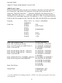
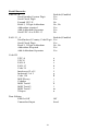
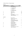
Table of Contents
Section 1. Introduction
Description 1
Section 2. Installation
Host Connections 2
Section 3. Configuration 3
Default Settings 5
Serial Interface Parameters 5
General Selections 7
Bar Code Message Formatting Selections 10
Magnetic Stripe Formatting Selections 12
Bar Code Selections 14
Magnetic Stripe Selections 27
Reviewing Configuration Selections 28
Section 4. Data Editing 30
Data Fields 31
Data Editing Formulas 32
The Formula Sequence 33
Data Editing Functions 34
Data Editing General Commands 35
Data Flow 40
Examples 41
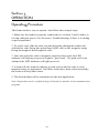
Section 5. Operation
Operating Procedure 44
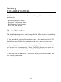
Section 6. Troubleshooting
General Procedures 45
Serial Interface Problems 46
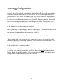
Scanning Configuration 47

Appendix A. Default Settings
Default Settings List 48
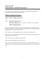
Appendix B. Magnetic Stripe Data Output Format
Magnetic Stripe Default Data Format 51
Appendix C. Magnetic Stripe Standard Data Formats
ISO Credit Card 52
California Driver’s License 53
AAMVA Driver’s License 55
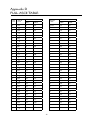
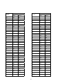
Appendix D. Full ASCII Table
ASCII Characters 56
Appendix E. Connector Pin Outs
RS-232 Ports 58
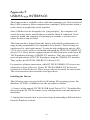
Appendix F. USB/RS-232 Interface
Installing the Drivers 59
Troubleshooting 62

1
Section 1
INTRODUCTION
Description
The Omni™
slot reader can scan and decode most popular bar codes, and/or
read 1, 2, or 3 tracks of magnetic stripe information, depending on the model.
In addition, it has full data editing capabilities.
The Omni can be connected to a single-ended serial device, such as a cash
register, PC, or terminal, through an RS-232 serial port or a USB port, de-
pending on the reader interface.
This unit is fully programmable via keystroke commands. The data can be
formatted with preamble/postamble and terminator characters to match the
format expected by the host. The programing codes are the same for both RS-
232 and USB/RS-232 units. Please see Appendix E for details.
Power is obtained from a separate power supply module when the unit is con-
figured as an RS-232 device. Power, when the reader is connected via a USB
port, is obtained from the host.

2
Section 2
INSTALLATION
Host Connections
The Omni reader is connected to the host’s RS-232 communications port. The
cable has a DB-9 connector at one end, and is connected to the reader at the
other end. (An adapter can be used to connect to a DB-25 RS-232 port.)
The USB/RS-232 version of the Omni is connected to one of the host’s USB
ports. It is necessary to configure the unit as an RS-232 device by installing
the ID TECH USB/RS-232 drivers. Please see Appendix F for details.
Data is transmitted to the host in an ASCII data format. The reader’s output
can be formatted with terminating characters and special preamble and/or
postamble character strings to match the data format expected by the terminal.
The terminal must be configured to accept the data and to perform the
appropriate processing. Care must be taken to ensure that the RS-232
parameters (baud rate, data bits, Start/Stop characters, parity, and handshaking
method) match those expected by the terminal. Just transmitting the data to
the serial port does not necessarily mean it will appear on the screen as if it
were entered manually.
If the host is programmable (such as a PC running in terminal mode), a
communication program, such as Procomm or Hyper Terminal, can be used to
display the data.
There is insufficient power available on a standard RS-232 serial port to
power the Omni, so an external wall-mounted power module must be used.
Connect the power cable from this unit to the power receptacle located on
the DB-9 connector. Care must be taken to ensure the power module operates
within +5VDC
+
10%.
When operating the USB/RS-232 version of the Omni, power is obtained
from the USB port. No external power module is necessary.

3
Section 3
CONFIGURATION
The Omni reader must be appropriately configured to your application.
Configuration settings enable the reader to work with the host system. These
settings are programmed into the reader through the keyboard. Once pro-
grammed, these configuration settings are stored in the reader’s non-volatile
memory (so they are not affected by the cycling of power).
Bar Code Input
The reader may need to be configured to accept the desired bar code data and
format it for transmission to the host. This includes enabling it for the correct
bar code symblogy, setting any check digit, start/stop codes, preamble/post-
amble, and min/max symbol length. Default settings enable all least restric-
tive settings.
Magnetic Stripe Input
The reader may need to be configured to accept the desired magnetic stripe
data and format it for transmission to the host. The encoded data can be
ANSI, ISO, AAMVA, and California Drivers License magnetic stripe formats.
The reader can be configured to read any track, 1 only, 2 only, 3 only, 1 & 2, 2
& 3, or 1,2 &3. In addition, track start/stop sentinels can be sent or suppressed
and track 2 account number information only can be selected along with user
selectable track separator characters. Default settings enable reading on all
available tracks (depending on whether the reader is equipped to read one,
two, or three tracks).
Configuration Setup Procedure
1. On an AT-compatible computer, enter any communication program. (Hyper
Terminal is recommend in the Windows environment.)
2. Turn on the CAPS LOCK feature on the keyboard, as the configuration
code is case sensitive.
3. Identify the settings that you wish to change. All options are covered in the
various setup groups explained in this manual. (The reader’s related setting
features are grouped together.)
4. Enter the GROUP SETUP MODE by typing /E/D/FX (where X is the
group name identified in Step 3).

4
5. Press the <Enter> key. The reader will beep twice to indicate the reader is
now in the Setup Mode for group X.
6. Type the two-character selection code for the feature that you wish to
change.
7. Press the <Enter> key. The reader will beep twice to indicate the code is
accepted by the reader as a valid code for Setup Group X.
8. Type the one-character code for the change you wish to make.
9. Press the <Enter> key. The reader will beep twice to indicate the code is
accepted by the reader as a valid code for that particular feature.
10. Repeat Steps 6 to 9 for any other features that you wish to change in the
same Setup Group.
11. Save the changes and exit Setup Mode by typing XZ. (Of course, X must
be the same group name entered in Step 4.)
12. Press the <Enter> key. The reader will sound four beeps to indicate
the new settings have been saved in the reader and the reader is back to the
normal reading mode.
EXAMPLE:
To set the reader’s beep volume to LOW, enter following setup code in
Notepad:
/E/D/FB<Enter>B1<Enter>1<Enter>BZ<Enter>
The setup routine is always the same, regardless of group:
1. Enter group setup mode.
2. Enter the feature selection code.
3. Change the setting for that feature.
4. Save the change and exit.
The reader’s response is always the same, regardless of group:
· Two slow beeps indicate the code has been accepted by the reader.
· Four slow beeps indicate the reader has saved the settings and has exited the
setup mode successfully.
· Four quick beeps indicate the code entered is invalid and has been rejected
by the reader.
Before proceeding to enter the next code, make sure the reader gives the correct
number of beeps when <ENTER> is depressed.

5
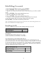
Default Settings
The Omni reader is shipped from the factory with the default settings already
programmed. In the following sections, the default settings are shown in
boldface. For a list of all default settings, please see Appendix A.
By default, the reader has been programmed with the least restricted settings,
thus making the Omni reader able to read most bar code labels and standard
format magnetic stripe cards out of box.
The reader’s output data format can be reconfigured to meet the expectations
of the host application.
To reset the reader to the factory default, follow these steps:
1. On an AT-compatible computer, enter any communication program. (Hyper
Terminal is recommend in the Windows environment.)
2. Turn on the CAPS LOCK feature on the keyboard, as the configuration
code is case sensitive.
3. Enter the GROUP SETUP MODE by typing /E/D/FA.
4. Press the <Enter> key. The reader will beep twice.
5. Type AW.
6. Press the <Enter> key. The reader will beep twice.
7. Type AZ.
8. Press the <Enter> key. The reader will sound four beeps.
Note: To check the firmware version, type AY <ENTER> before AZ <ENTER>.
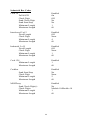
Serial Interface Parameters (Group E)
This group of settings specifies the parameters used for serial communica-
tions. The settings will be active for the host/terminal serial interface.
1. Enter SERIAL INTERFACE SETUP MODE by typing /E/D/FE.
2. Press <ENTER>. The reader should beep twice.
3. Type the two-character code for the feature you wish to change.
4. Press <ENTER>. The reader should beep twice.

6
5. Type the one-character code for the change you wish to make.
6. Press <ENTER>. The reader should beep twice.
7. Save the setting and exit the Group Setup Mode by typing EZ.
8. Press <ENTER>. The reader should beep four times.
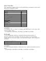
Baud Rate
The baud rate is the speed at which data is transmitted and received.
SELECTION CODE: E1
300 bps A
1200 bps C
2400 bps D
4800 bps E
9600 bps F
19200 bps G
Data Bits
Set the number of data bits used to define a character.
SELECTION CODE: E2
7 bits A
8 bits B
Parity
Serial communication can define a parity check bit to be added to each
character. This check bit can be true for an odd number of “1” bits or an even
number of “1” bits in the data character. The user may also choose to define
the parity bit as a MARK (true) or a SPACE (false). Selecting NONE results
in no parity bit.
SELECTION CODE: E3
Odd A
Even B
Mark C
Space D
None E
Note: The reader must use a total of 10 or 11 bits to define a character frame.
If you select “7” data bits with the “None” parity option, the reader will for-
mat the character frame as 8 data bits and no parity.

7
Handshaking
Some type of flow control or “handshaking” must be used between two
devices to prevent data from being transmitted before the receiving device
is ready to accept it. Handshake signals interrupt the flow of data until the
receiving device is ready.
SELECTION CODE: E4
X-On/X-Off A
RTS/CTS B
Stop Bit
The stop bit function defines the number of bits used to end the data frame.
Older equipment sometimes requires extra time after receiving a character in
order to process it, and therefore requires two stop bits.
SELECTION CODE: E5
1 bit A
2 bits B
EXAMPLE:
To set the reader to 9600 bps, 7 bits, Even, enter:
/E/D/FE<ENTER>E2<ENTER>A<ENTER>E3<ENTER>B<ENTER>EZ
<ENTER>
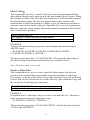
General Selections (Group B)
The basic operating parameters of the Omni reader can be programmed with
this group of selections.
1. Enter GROUP SETUP MODE by typing /E/D/FB .
2. Press <ENTER>. The reader should beep twice.
3. Type the two-character selection code for the feature you wish to change.
4. Press <ENTER>. The reader should beep twice.
5. Type the one-character code for the change you wish to make.
6. Press <ENTER>. The reader should beep twice.
7. Save the setting and exit the Group Setup Mode by typing BZ.
8. Press <ENTER>. The reader should beep four times.
Note: To review the group’s current setting(s), type BY<ENTER> while in Group
Setup Mode. To reset the current setting(s) to its group default, type BX<ENTER>
while in the Group Setup Mode.
EXAMPLE:
To set the current settings to the group default, enter:
/E/D/FB<ENTER>BX<ENTER>BZ<ENTER>

8
Beep Volume
The beep volume can be adjusted to two different levels, or turned off en-
tirely.
SELECTION CODE: B1
Off 0
Low 1
High 2
Code/Track ID
Each bar code symbology or MSR track can be assigned a CODE ID charac-
ter. This character is added to the beginning of the scanned data. The host can
use this character to ensure that the data received came from the appropriate
type of symbol.
SELECTION CODE: B5
On A
Off B
Scan Verification
In order to insure accuracy of scanned data from poor-contrast bar code
labels, a second confirmation swipe can be required before the reader will
accept the data. When this option is enabled the reader requires the card to be
swiped a second time and both swipes are compared. If they match, the data is
considered good.
SELECTION CODE: B6
On A
Off B
Note: This function applies to bar codes only.

9
Code ID Definition (Group I)
If the Code ID option is enabled in General Setup, the user can select the
character used to identify each symbology.
1. Enter CODE ID DEFINITION SETTINGS MODE by typing /E/D/FI.
2. Press <ENTER>. The reader should beep twice.
3. Enter the characters in the left column to select the symbology.
4. Press <ENTER>. The reader should beep twice.
5. Enter one character for the new ID.
a UPC-A Default = a
b UPC-E Default = b
c EAN-8 Default = c
d EAN-13 Default = d
e Code 39 Default = e
f Interleaved 2 of 5 Default = f
g Industrial 2 of 5 Default = g
h Code 128 Default = h
i MSI/Plessey Default = i
j Codabar Default = j
k MSR Track 1 Default = k
l MSR Track 2 Default = l
m MSR Track 3 Default = m
n Telepen Default = n
6. Press <ENTER>. The reader should beep twice.
7. Save the change and exit the group setup mode by entering IZ<ENTER>.
The reader should beep four times.
Note: To review the group’s current setting(s), type IY<ENTER> while in the Group
Setup Mode. To reset the current setting(s) to its group default, type IX<ENTER>
while in the Group Setup Mode.
EXAMPLE:
To change Code ID for Code 128 from h to w, enter:
/E/D/FI<ENTER>h<ENTER>w<ENTER>IZ<ENTER>

10
Bar Code Message Formatting Selections (Group C )
Scanned bar code data can be formatted with the addition of preambles,
postambles, and terminator characters. The settings below will augment bar
code data scanned by the Omni. A fully-formatted message block reflects the
following model:
{Preamble}{Code ID}{Data}{Terminator}{Postamble}
1. Enter BAR CODE MESSAGE FORMATTING SETUP MODE by typing
/E/D/FC.
2. Press <ENTER>. The reader should beep twice.
3. Type the two-character selection code for the feature you wish to change.
4. Press <ENTER>. The reader should beep twice.
5. Type the one-character code for the change you wish to make.
6. Press <ENTER>. The reader should beep twice.
7. Save the change and exit the Bar Code Setup Mode by typing CZ.
8. Press <ENTER>. The reader should beep four times.
Note: To review the group’s current setting(s), type CY<ENTER> while in the setup
mode. To reset the current setting(s) to its group default, type CX<ENTER> while in
Bar Code Setup Mode.
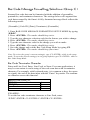
Bar Code Terminator Character
Enter and Line Feed, Enter, Line Feed, or None: For some applications, it
may be convenient to end a string of bar code scan data with a terminator
character. For example, with keyboard entry, it is common to have the opera-
tor signify the end of the data input with the “Enter” keystroke. The termina-
tor character serves this function.
SELECTION CODE: C1
RETURN and Line Feed A
RETURN B
Line Feed C
None D
EXAMPLE:
To set the bar code terminator character to Line Feed, enter:
/E/D/FC<ENTER>C1<ENTER>C<ENTER>CZ<ENTER>

11
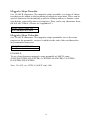
Bar Code Preamble
0 to 16 ASCII characters: The bar code preamble is a string of characters that
can be added to the beginning of scanned bar code data. These can be special
characters for identifying a specific scanning station, to format a message
header expected by the receiving host. They can be any characters from the
full ASCII table. (Please see Appendix D.)
SELECTION CODE: C2
One Character at a time
Bar Code Postamble
0 to 16 ASCII characters: The bar code postamble serves the same purpose
as the preamble, except it is added to the end of the scanned data after any
terminator characters.
SELECTION CODE: C3
One Character at a time
EXAMPLE:
To set a four-character bar code preamble of ABCD, enter:
/E/D/FC<ENTER>C2<ENTER>A<ENTER>B<ENTER>C<ENTER>
D<ENTER>CZ<ENTER>
Note: For CR, use CTRL-N (ASCII code 14h).

12
Magnetic Stripe Formatting Selections (Group D)
Magnetic stripe output can also be formatted with the addition of preambles,
postambles, and terminator characters. The settings below will augment mag-
netic stripe data read by the Omni. A fully-formatted message block reflects
the following model:
{Preamble}{T1 ID}{T1 Data}{Track Separator}{T2 ID}{T2 Data}{Track
Separator}{T3 ID}{T3 Data}{Terminator}{Postamble}
1. Enter MAGNETIC STRIPE FORMATTING SETUP MODE by typing
/E/D/FD.
2. Press <ENTER>. The reader should beep twice.
3. Type the two-character selection code for the feature you wish to change.
4. Press <ENTER>. The reader should beep twice.
5. Type the one-character code for the change you wish to make.
6. Press <ENTER>. The reader should beep twice.
7. Save the change and exit the Magnetic Stripe Setup Mode by typing DZ.
8. Press <ENTER>. The reader should beep four times.
Note: To review the group’s current setting(s), type DY<ENTER> while in the Mag-
netic Stripe Formatting Setup Mode. To reset the current setting(s) to its group default,
type DX<ENTER> while in Formatting Mode.
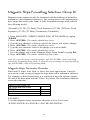
Magnetic Stripe Terminator Character
Enter and LF, Enter, Line Feed, or None: For some applications, it may be
convenient to end a string of magnetic stripe data with a terminator character.
For example, with keyboard entry, it is common to have the operator signify
the end of the data input with the “Enter” keystroke. The terminator character
serves this function.
SELECTION CODE: D1
RETURN and Line Feed A
RETURN B
Line Feed C
None D
EXAMPLE:
To set the magnetic stripe terminator character to Line Feed, enter:
/E/D/FD<ENTER>D1<ENTER>C<ENTER>DZ<ENTER>

13
Magnetic Stripe Preamble
0 to 16 ASCII characters: The magnetic stripe preamble is a string of charac-
ters that can be added to the beginning of magnetic stripe data. These can be
special characters for identifying a specific reading station, to format a mes-
sage header expected by the receiving host. They can be any characters from
the full ASCII table. (Please see Appendix D.)
SELECTION CODE: D2
One Character at a time
Magnetic Stripe Postamble
0 to 16 ASCII characters: The magnetic stripe postamble serves the same
purpose as the preamble, except it is added to the end of the read data after
any terminator characters.
SELECTION CODE: D3
One Character at a time
EXAMPLE:
To set a four-character magnetic stripe preamble of ABCD, enter:
/E/D/FD<ENTER>D2<ENTER>A<ENTER>B<ENTER>C<ENTER>
D<ENTER>DZ<ENTER>
Note: For CR, use CTRL-N (ASCII code 14h).

14
Bar Code Selections
Bar code selections for the Omni are separated into two groups: Industrial
and Retail. Industrial bar codes may contain a variable number of characters.
Retail bar codes always contain a specific number of characters.
Industrial Bar Codes (Group F)
1. Enter INDUSTRIAL BAR CODE SETUP MODE by typing /E/D/FF.
2. Press <ENTER>. The reader should beep twice.
3. Type the two-character selection code for the bar code symbology you wish
to change.
4. Press <ENTER>. The reader should beep twice.
5. Type the one-character code for the change you wish to make.
6. Press <ENTER>. The reader should beep twice.
7. Save the change and exit the Industrial Bar Code Setup Mode by typing
FZ.
8. Press <ENTER>. The reader should beep four times.
Note: To review the group’s current setting(s), type FY<ENTER> while in the Indus-
trial Bar Code Setup Mode. To reset the current setting(s) to its group default, type
FX<ENTER> while in Industrial Bar Code Setup Mode.
Minimum and Maximum Length Options
You can set minimum and maximum length standards for a particular indus-
trial bar code symbology. (You cannot set a minimum or maximum length for
a retail bar code.)
Minimum length sets the minimum number of data characters that will be
accepted for this symbology. If the minimum length is set higher than the
maximum length, all readings will be rejected.
Maximum length sets the maximum number of data characters that will be
accepted for this symbology. If the maximum length is set lower than the
minimum length, all readings will be rejected.
To set the minimum and maximum length for a particular symbology:
1. Enter Setup Mode by typing /E/D/FF.
2. Press <ENTER>. The reader should beep twice.
3. Enter the selection code for the particular symbology selected (such as
F4<ENTER> for Code 128). The reader should beep twice.
4. Enter FU<ENTER> for minimum or FV<ENTER> for maximum. The
reader should beep twice.

15
5. Enter one digit <ENTER> one digit <ENTER> from the keyboard. (The
range is 01 to 60). The reader should beep twice after each <ENTER>.
6. Save and exit by typing FZ<ENTER>. The reader should beep four times.
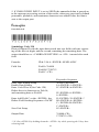
EXAMPLE:
To set the maximum length of a Code 39 bar code to 12, enter:
/E/D/FF<ENTER>F1<ENTER>FV<ENTER>1<ENTER>2<ENTER>
FZ<ENTER>
Code 39 Settings:
Enable/Disable Code 39
If enabled, Code 39 symbology will be read, subject to the reading restrictions
specified by this set of options. If disabled, the data from the symbology will
be disregarded.
SELECTION CODE: F1
Code 39 Enable A
Code 39 Disable B
Full ASCII
Standard Code 39 symbology supports only 43 characters. This can be ex-
panded by using character pairs to identify the full ASCII 128 character set.
When this option is ON, the reader will search for these character pairs and
transmit only the Full ASCII single character equivalent to the host. If Full
ASCII is enabled and used to read a standard Code 39 symbol, any combina-
tion of the defined character pairs will be reported to the host as the single
character equivalent. When this option is OFF and a Full ASCII Code 39
symbol is scanned, the reader will report each of the characters in the Full
ASCII pair as individual characters. The reader has no way of telling if the
symbol is encoded in standard Code 39 or Full ASCII Code 39.
SELECTION CODE: F1
Full ASCII On C
Full ASCII Off D

16
Check Digit
When Check Digit is selected, the reader takes the last character in the de-
coded data stream as a check digit. It then calculates the correct check digit
for the remaining data and compares it to the last data character. If it is the
same, the data is accepted. If not, the data is rejected. With the Calculate and
Send Check Digit option, the reader will send the check digit as part of the
data stream. If the Calculate but Do Not Send Check Digit option is selected,
the reader will strip it from the data stream before transmission. If the Check
Digit is not calculated, the reader will assume the last data character read
from the symbol is part of the data stream and will not make a comparison
test.
SELECTION CODE: F1
Do Not Calculate Check Digit but Send Whole Data Stream E
Calculate and Send Check Digit F
Calculate but Do Not Send Check Digit G
Send Start/Stop Characters
A unique character is used as the first and last character in a Code 39 symbol.
It is printed as an asterisk (*). Some applications require that these characters
be transmitted with the data while others specify that they must not be sent.
SELECTION CODE: F1
Send Start/Stop H
Do Not Send Start/Stop I
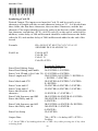
EXAMPLE:
To disable the Full ASCII Code 39, enter:
/E/D/FF<ENTER>F1<ENTER>D<ENTER>FZ<ENTER>
Interleaved 2 of 5 Settings:
Enable/Disable Interleaved 2 of 5
If enabled, Interleaved 2 of 5 symbology will be read, subject to the read-
ing restrictions specified by this set of options. If disabled, the data from the
symbology will be disregarded.
SELECTION CODE: F2
Interleaved 2 of 5 Enable A
Interleaved 2 of 5 Disable B
Page is loading ...
Page is loading ...
Page is loading ...
Page is loading ...
Page is loading ...
Page is loading ...
Page is loading ...
Page is loading ...
Page is loading ...
Page is loading ...
Page is loading ...
Page is loading ...
Page is loading ...
Page is loading ...
Page is loading ...
Page is loading ...
Page is loading ...
Page is loading ...
Page is loading ...
Page is loading ...
Page is loading ...
Page is loading ...
Page is loading ...
Page is loading ...
Page is loading ...
Page is loading ...
Page is loading ...
Page is loading ...
Page is loading ...
Page is loading ...
Page is loading ...
Page is loading ...
Page is loading ...
Page is loading ...
Page is loading ...
Page is loading ...
Page is loading ...
Page is loading ...
Page is loading ...
Page is loading ...
Page is loading ...
Page is loading ...
Page is loading ...
Page is loading ...
Page is loading ...
Page is loading ...
Page is loading ...
Page is loading ...
Page is loading ...
-
 1
1
-
 2
2
-
 3
3
-
 4
4
-
 5
5
-
 6
6
-
 7
7
-
 8
8
-
 9
9
-
 10
10
-
 11
11
-
 12
12
-
 13
13
-
 14
14
-
 15
15
-
 16
16
-
 17
17
-
 18
18
-
 19
19
-
 20
20
-
 21
21
-
 22
22
-
 23
23
-
 24
24
-
 25
25
-
 26
26
-
 27
27
-
 28
28
-
 29
29
-
 30
30
-
 31
31
-
 32
32
-
 33
33
-
 34
34
-
 35
35
-
 36
36
-
 37
37
-
 38
38
-
 39
39
-
 40
40
-
 41
41
-
 42
42
-
 43
43
-
 44
44
-
 45
45
-
 46
46
-
 47
47
-
 48
48
-
 49
49
-
 50
50
-
 51
51
-
 52
52
-
 53
53
-
 54
54
-
 55
55
-
 56
56
-
 57
57
-
 58
58
-
 59
59
-
 60
60
-
 61
61
-
 62
62
-
 63
63
-
 64
64
-
 65
65
-
 66
66
-
 67
67
-
 68
68
-
 69
69


Ask a question and I''ll find the answer in the document
Finding information in a document is now easier with AI
Related papers
Other documents
-
Zebex ZM-800 Quick start guide
-
Intermec MicroBar NX Installation guide
-
-
-
-
-
Microscan QX-870 Industrial Raster Laser Scanner User manual
-
Unitech K2726 User manual
-
-
Datalogic Scanning DS1100 SH2347 User manual