
CLM HD8
User guide
R9050130
R90501301
R90501305
R59770057/08
15/03/2010

Barco nv Events
Noordlaan 5, B-8520 Kuurne
Phone: +32 56.36.82.11
Fax: +32 56.36.88.24
E-mail: [email protected]
Visit us at the web: www.barco.com
Printed in Belgium

Changes
Barco provides this manual ’as is’ without warranty of any kind, either expressed or implied, including but not limited to the implied war-
ranties or merchantability and fi tness for a particular purpose. Barco may make improvements and/or changes to the product(s) and/or the
program(s) described in this publication at any time without notice.
This publication could contain technical inaccuracies or typographical errors. Changes are periodically made to the information in this
publication; these changes are incorporated in new editions of this publication.
Copyright ©
All rights reserved. No part of this document may be copied, reproduced or translated. It shall not other
wise be recorded, transmitted or
stored in a retrieval system without the prior written consent of Barco.
Trademarks
Brand and product names mentioned in this manual may be trademarks, registered trademarks or copyrights of their respective holders.
All brand and product names mentioned in this manual serve as comments or examples and are not to be understood as advertising for
the products or their manufacturers.
Federal Communications Commission (FCC Statement)
This equipment has been tested and found to comply with the limits for a class A digital device, pursuant to Part 15 of the FCC rules.
These limits are designed to provide reasonable protection against harmful interference when the equipment is operated in a commercial
environment. This equipment generates, uses, and can radiate radio frequency energy and, if not installed and used in accordance with
the instruction manual, may cause harmful interference to radio communications. Operation of this equipment in a residential area may
cause harmful interference, in which case the user will be responsible for correcting any interference at his own expense
EN55022/CISPR22 Class A ITE (Information Technology Equipment)
Class A ITE is a category of all other ITE which satisfies the class A ITE limits but not the class B ITE limits. Such equipment should not
be restricted in its sale but the following warning shall be included in the instructions for use:
Warning : This is a class A product. In a domestic environment this product may cause radio interference in which case the user may be
required to take adequate measures.
Guarantee and Compensation
Barco provides a guarantee relating to perfect manufacturing as part of the legally stipulated terms of guarantee. On receipt, the purchaser
must immediately inspect all delivered goods for damage incurred during transport, as well as for material and manufacturing faults Barco
must be informed immediately in writing of any complaints.
The period of guarantee begins on the date of transfer of risks, in the case of special systems and software on the date of commissioning,
at latest 30 days after the transfer of risks. In the event of justified notice of complaint, Barco can repair the fault or provide a replacement
at its own discretion within an appropriate period. If this measure proves to be impossible or unsuccessful, the purchaser can demand a
reduction in the purchase price or cancellation of the contract. All other claims, in particular those relating to compensation for direct or
indirect damage, and also damage attributed to the operation of software as well as to other services provided by Barco, being a component
of the system or independent service, will be deemed invalid provided the damage is not proven to be attributed to the absence of properties
guaranteed in writing or due to the intent or gross negligence or part of Barco.
If the purchaser or a third party carries out modifications or repairs on goods delivered by Barco, or if the goods are handled incorrectly,
in particular if the systems are commissioned operated incorrectly or if, after the transfer of risks, the goods are subject to influences not
agreed upon in the contract, all guarantee claims of the purchaser will be rendered invalid. Not included in the guarantee coverage are
system failures which are attributed to programs or special electronic circuitry provided by the purchaser, e.g. interfaces. Normal wear as
well as normal maintenance are not subject to the guarantee provided by Barco either.
The environmental conditions as well as the servicing and maintenance regulations specified in the this manual must be complied with by
the customer.
Software License Agreement
You should carefully read the following terms and conditions before using this software. Your use of this software indicates your acceptance
of this license agreement and warranty.
Terms and Conditions:
1. No redistribution of the software is allowed.
2. Reverse-Engineering. You may
not reverse engineer, decompile, disassemble or alter anyhow this software product.
Disclaimer of Warranty:

This software and the accompanying files are sold “as is” and without warranties as to performance or merchantability or any other war-
ranties whether expressed or implied. In no event shall Barco be liable for damage of any kind, loss of data, loss of profits, business
interruption or other pecuniary loss arising directly or indirectly. Any liability of the seller will be exclusively limited to replacement of the
product or refund of purchase price.
GNU-GPL code
If you would like a copy of the GPL source code contained in this product shipped to you on CD, please contact Barco. The cost of preparing
and mailing a CD will be charged.
Disposal Information
This equipment has required the extraction and use of natural resources for its production. It may contain hazardous substances for health
and environment. In order to avoid the dissemination of those substances in the environment and to diminish the pressure on natural
resources, we encourage you to use the appropriate take-back systems. Those systems will reuse or recycle most of the materials of your
end of life equipment in a sound way.
The crossed-out wheeled bin symbol invites you to use those systems. If you need more information on the collection, reuse and recycling
systems, please contact your local or regional waste administrator. You can also contact us for more information on the environmental
performances of our products.

Table of contents
TABLE OF CONTENTS
1. Safety................................................................................................................. 5
1.1 General ............................................................................................................................... 5
1.2 Important safety instructions ......................................................................................................... 6
1.3 Recycling guidelines.................................................................................................................. 8
1.4 Important warnings concerning CLM flight cases ................................................................................... 9
2. General..............................................................................................................11
2.1 Installation requirements . . . ......................................................................................................... 11
2.2 Unpacking the projector .............................................................................................................12
2.3 Box content.......................................................................................................................... 13
2.4 Projector configurations ............................................................................................................. 14
2.5 Projector air inlets and outlets.......................................................................................................17
2.6 Free download of Projector Toolset................................................................................................. 17
3. Physical installation ..............................................................................................19
3.1 Remote control unit (RCU) . .........................................................................................................19
3.1.1 RCU battery installation.......................................................................................................20
3.1.2 RCU rugged case installation ................................................................................................21
3.1.3 RCU XLR adaptor installation ................................................................................................ 21
3.1.4 Using the XLR adaptor of the RCU. . . ........................................................................................22
3.1.5 RCU usage possibilities ......................................................................................................22
3.2 Lenses ...............................................................................................................................23
3.2.1 Available lenses...............................................................................................................23
3.2.2 Lens selection................................................................................................................. 23
3.2.3 Lens formulas .................................................................................................................24
3.3 Alignment of a table mounted CLM projector....................................................................................... 24
3.4 Suspension of the CLM projector with rigging clamps . . ...........................................................................25
3.5 Alignment of a ceiling mounted CLM projector . . ................................................................................... 29
4. Stacking CLM projectors.........................................................................................31
4.1 Stacking CLM projectors ............................................................................................................ 31
4.2 Aligning stacked CLM projectors.................................................................................................... 33
5. Connections........................................................................................................35
5.1 Power connection . . ................................................................................................................. 35
5.2 Input source connections. .. .........................................................................................................37
5.3 Communication connections ........................................................................................................ 39
6. Getting started.....................................................................................................43
6.1 RCU & Local keypad ................................................................................................................ 43
6.2 Terminology overview ...............................................................................................................43
6.3 Operating the projector..............................................................................................................45
6.3.1 Switching on................................................................................................................... 45
6.3.2 Errors, warnings and messages during start up .. ...........................................................................46
6.3.3 Switching to standby . ......................................................................................................... 46
6.3.4 Switching off...................................................................................................................47
6.4 Using the RCU.......................................................................................................................47
6.5 Quick setup adjustments ............................................................................................................48
6.5.1 Text boxes ON or OFF........................................................................................................48
6.5.2 Quick Lens Adjustment ....................................................................................................... 48
6.5.2.1 Quick Lens Adjustment via LENS key .................................................................................48
6.5.2.2 Direct Lens Adjustment (RCU). ........................................................................................49
6.5.3 Quick picture in picture .......................................................................................................50
6.5.4 Quick layout selection with Rigging key......................................................................................50
6.5.5 Quick language selection . . ...................................................................................................51
6.6 Use of the AUTO button............................................................................................................. 51
6.7 Projector Address.................................................................................................................... 51
6.7.1 Displaying and Programming addresses. . ................................................................................... 51
6.7.2 Controlling the projector ......................................................................................................52
6.8 Source selection.....................................................................................................................53
6.9 Controlling the Projector............................................................................................................. 53
7. Start up of the adjustment mode ...............................................................................55
7.1 About the adjustment mode ......................................................................................................... 55
7.2 About the use of the remote control and the local keypad.........................................................................55
7.3 Start up the adjustment mode....................................................................................................... 55
7.4 Navigation and adjustments......................................................................................................... 56
7.5 On screen menus versus LCD display menus . . ...................................................................................56
8. Input menu .........................................................................................................59
8.1 Overview flow........................................................................................................................59
8.2 Slot module type.....................................................................................................................59
8.2.1 About Input Setup.............................................................................................................59
R59770057 CLM HD8 15/03/2010
1

Table of contents
8.2.2 Input configuration ............................................................................................................ 60
8.3 Input locking . ........................................................................................................................ 61
8.4 Minimum delay....................................................................................................................... 63
8.5 Native resolution..................................................................................................................... 63
8.6 Source switching ....................................................................................................................65
8.7 No signal .............................................................................................................................65
8.7.1 Background color ............................................................................................................. 66
8.7.2 Shutdown setting..............................................................................................................66
8.7.3 Shutdown retarding time......................................................................................................66
9. Image menu ........................................................................................................69
9.1 Overview flow........................................................................................................................69
9.2 How to select the image adjustments? . . . . . ........................................................................................70
9.3 Image Settings....................................................................................................................... 70
9.3.1 Contrast ....................................................................................................................... 71
9.3.2 Brightness..................................................................................................................... 71
9.3.3 Saturation ..................................................................................................................... 72
9.3.4 Tint (hue)...................................................................................................................... 73
9.3.5 Phase.......................................................................................................................... 73
9.3.6 Sharpness.....................................................................................................................74
9.3.7 Noise reduction ............................................................................................................... 75
9.3.8 Color temperature............................................................................................................. 76
9.3.8.1 Predefined color temperature..........................................................................................76
9.3.8.2 Set a custom color temperature ....................................................................................... 77
9.3.9 Input balance.................................................................................................................. 78
9.3.9.1 Introduction to Input Balance . . ........................................................................................ 78
9.3.9.2 Adjusting the input balance ............................................................................................79
9.4 Aspect ratio ..........................................................................................................................82
9.5 Timings...............................................................................................................................83
9.5.1 Source timings ................................................................................................................83
9.5.2 Advanced settings ............................................................................................................84
9.5.3 Advanced settings, film mode detection ..................................................................................... 86
9.5.4 Advanced setting, brilliant color look.........................................................................................87
9.6 Image files services .................................................................................................................88
9.6.1 Files and file manipulations. ..................................................................................................88
9.6.2 Manual Load file ..............................................................................................................89
9.6.3 Delete file......................................................................................................................89
9.6.4 Delete all custom files ........................................................................................................ 90
9.6.5 Rename a file ................................................................................................................. 91
9.6.6 Copy a file.....................................................................................................................92
9.6.7 File options....................................................................................................................92
9.7 Save custom settings................................................................................................................ 93
10. Layout menu .......................................................................................................95
10.1 Overview flow........................................................................................................................ 95
10.2 Main window .........................................................................................................................95
10.2.1 Source selection ..............................................................................................................96
10.2.2 Size adjustment...............................................................................................................96
10.2.3 Position adjustment...........................................................................................................99
10.3 PIP window . . .......................................................................................................................100
10.3.1 Introduction to PIP . . .........................................................................................................100
10.3.2 Picture in Picture activation..................................................................................................101
10.3.3 Picture in Picture source selection ..........................................................................................101
10.3.4 Picture in Picture size of the window . .......................................................................................102
10.3.5 Picture in Picture, position window . . . .......................................................................................105
10.4 Layout file services .................................................................................................................106
10.4.1 Load layout. . . ................................................................................................................106
10.4.2 Rename a layout .............................................................................................................107
10.4.3 Delete a layout...............................................................................................................107
10.4.4 Copy / Save as a layout .....................................................................................................108
11. Lamp menu........................................................................................................111
11.1 Overview flow.......................................................................................................................111
11.2 Lamp power mode..................................................................................................................111
11.3 Lamp power.........................................................................................................................112
11.4 Lamp Identification .................................................................................................................113
11.5 Status and run time overview lamps...............................................................................................114
11.6 Lamp mode .........................................................................................................................114
12. Alignment menu................................................................................................. 115
12.1 Overview flow.......................................................................................................................115
12.2 Orientation ..........................................................................................................................116
12.3 Lens adjustment ....................................................................................................................117
12.4 Side keystone.......................................................................................................................118
12.5 Blanking.............................................................................................................................119
12.6 Intensity.............................................................................................................................120
12.7 Gamma .............................................................................................................................120
2
R59770057 CLM HD8 15/03/2010

Table of contents
12.8 Internal pattern......................................................................................................................121
12.9 Color space.........................................................................................................................122
12.10 White peaking ......................................................................................................................123
12.11 ScenergiX ...........................................................................................................................124
12.11.1 Introduction. . . ................................................................................................................124
12.11.2 Preparations. .................................................................................................................125
12.11.3 ScenergiX activation . ........................................................................................................125
12.11.4 ScenergiX pattern............................................................................................................125
12.11.5 ScenergiX overlap zone (horizontal ScenergiX) . . ..........................................................................126
12.11.6 ScenergiX overlap zone (vertical ScenergiX) ...............................................................................128
12.11.7 ScenergiX size adjustment (White level). . ..................................................................................129
12.11.8 Adjusting the black level of the images . . . ..................................................................................131
13. Projector control ................................................................................................ 135
13.1 Overview flow.......................................................................................................................135
13.2 Projector address. . .................................................................................................................136
13.2.1 Individual projector address .................................................................................................136
13.2.2 Common address ............................................................................................................137
13.3 Serial communication...............................................................................................................137
13.3.1 Baud rate setup ..............................................................................................................138
13.3.2 Interface standard............................................................................................................138
13.3.3 RS422 termination.......................................................................................................... .139
13.4 Network .............................................................................................................................139
13.4.1 Introduction to a Network connection .......................................................................................140
13.4.2 DHCP setup . . ................................................................................................................140
13.4.3 IP-address set up ............................................................................................................141
13.4.4 Subnet-mask set up..........................................................................................................141
13.4.5 Default Gateway set up......................................................................................................142
13.5 IR control switching.................................................................................................................143
13.6 DMX.................................................................................................................................144
13.6.1 DMX address. ................................................................................................................144
13.6.2 DMX universe................................................................................................................145
13.6.3 DMX monitor .................................................................................................................145
13.6.4 DMX mode . . .................................................................................................................147
13.6.5 Art-Net Activation ............................................................................................................147
13.7 Buttons..............................................................................................................................148
13.7.1 APA button ...................................................................................................................148
13.7.2 Shortcut keys.................................................................................................................148
13.8 Menu position.......................................................................................................................149
13.9 Local LCD contrast .................................................................................................................150
13.10 Language selection.................................................................................................................150
14. Service menu..................................................................................................... 153
14.1 Overview flow.......................................................................................................................153
14.2 Identification ........................................................................................................................153
14.3 Diagnosis ...........................................................................................................................155
14.3.1 How to start up the diagnosis? ..............................................................................................155
14.3.2 Versions ......................................................................................................................155
14.3.3 Voltages ......................................................................................................................156
14.3.4 I²C diagnosis . ................................................................................................................157
14.3.5 Temperatures ................................................................................................................157
14.3.6 Fan speeds overview ........................................................................................................158
14.3.7 SPI............................................................................................................................159
14.3.8 Error logging overview.......................................................................................................159
14.4 Internal service patterns............................................................................................................160
14.5 Restore factory defaults............................................................................................................160
14.6 Save custom settings...............................................................................................................161
14.7 Refill mode . . . .......................................................................................................................162
14.8 USB memory .......................................................................................................................163
14.9 Over temperature DMD safety .....................................................................................................164
15. Maintenance...................................................................................................... 167
15.1 Cleaning the lens . . .................................................................................................................167
15.2 Cleaning the exterior of the projector ..............................................................................................167
15.3 Level check of cooling liquid .......................................................................................................167
16. Servicing.......................................................................................................... 169
16.1 Replacement of the dust filter on the top side.....................................................................................169
16.2 Replacement of the dust filters on the front side ..................................................................................170
16.3 Lens installation ....................................................................................................................171
16.4 Lens removal .......................................................................................................................172
16.5 Removal of a lamp unit.............................................................................................................173
16.6 Mounting a new lamp unit . . ........................................................................................................175
16.7 Removal of an input module .......................................................................................................176
16.8 Inserting an input module . . ........................................................................................................177
16.9 Top-up the reservoir with cooling liquid............................................................................................177
R59770057 CLM HD8 15/03/2010
3

Table of contents
17. Projector covers, removal and installation ................................................................. 181
17.1 Removal of the front cover .........................................................................................................181
17.2 Removal of the lamp door. . ........................................................................................................182
17.3 Removal of the back cover.........................................................................................................183
17.4 Removal of the top cover...........................................................................................................184
17.5 Removal of the side cover..........................................................................................................184
17.6 Installation of the side cover .......................................................................................................185
17.7 Installation of the top cover.........................................................................................................186
17.8 Installation of the back cover.......................................................................................................186
17.9 Installation of the front cover.......................................................................................................187
17.10 Installation of the lamp door........................................................................................................188
A. Dimensions ........................................................................................................ 191
A.1 Dimensions of the CLM HD8.......................................................................................................191
B. Standard Source Files ........................................................................................... 193
B.1 Table overview......................................................................................................................193
C. DMX Chart.......................................................................................................... 195
C.1 CLM control channel mapping (Full mode) . .......................................................................................195
C.2 CLM control channel mapping (Basic mode) ......................................................................................196
D. Specifications ..................................................................................................... 199
D.1 Specifications CLM HD8 ...........................................................................................................199
D.2 Specifications CLM 5 cable input (multi purpose).................................................................................201
D.3 Specifications CLM HDSDI – SDI input. . .. . .......................................................................................202
D.4 Specifications CLM DVI input ......................................................................................................203
D.5 Specifications CLM DVI HDCP input ..............................................................................................203
E. Troubleshooting.... .......... .... .......... .... ...... .... .... ...... .... .... ...... .... .......... .... .......... .... . 205
E.1 Error codes .. .......................................................................................................................205
F. Mounting optional Carry handle ..... .... ...... .... ...... .... ...... .... ...... ...... .... ...... .... ...... .... ..... 211
F.1 Mounting stacking points on top cover.............................................................................................211
F.2 Preparing the new carry handle.. . .................................................................................................212
F.3 Preparing the projector .............................................................................................................213
F.4 Mounting the carry handle. . ........................................................................................................214
G. Order info .......................................................................................................... 217
G.1 Spare part order info ...............................................................................................................217
Glossary ............................................................................................................... 219
Index.................................................................................................................... 221
4 R59770057 CLM HD8 15/03/2010

1. Safety
1. SAFETY
About this chapter
Read this chapter attentively. It contains important information to prevent personal injury while installing and using an CLM HD8
projector. Furthermore, it includes several cautions to prevent damage to the CLM HD8. Ensure that you understand and follow
all safety guidelines, safety instructions and warnings mentioned in this chapter before installing your CLM projector. After this
chapter, additional “warnings” and “cautions” are given depending on the installation procedure. Read and follow these “warnings”
and “cautions” as well.
Overview
• General
• Important safety instructions
• Recycling guidelines
• Important warnings concerning CLM flight cases
1.1 General
Notice on safety
This equipment is built in accordance with the requirements of the international safety standards IEC60950-1, EN60950-1,
UL60950-1 and CAN/CSA C22.2 No.60950-1, which are the safety standards of information technology equipment including
electrical business equipment. These safety standards impose important requirements on the use of safety critical components,
materials and insulation, in order to protect the user or operator against risk of electric shock and energy hazard, and having
access to live parts. Safety standards also impose limits to the internal and external temperature rises, radiation levels, mechanical
stability and strength, enclosure construction and protection against the risk of fire. Simulated single fault condition testing ensures
the safety of the equipment to the user even when the equipment’s normal operation fails.
Installation instructions
• Before operating this equipment please read this manual thoroughly, and retain it for future reference.
• Installation and preliminary adjustments should be performed by qualified Barco personnel or by authorized Barco service deal-
ers.
• All warnings on the projector and in the documentation manuals should be adhered to.
• All instructions for operating and use of this equipment must be followed precisely.
Definition of “qualified service technicians” or ”qualified technicians”: Persons having appropriate technical
training and experience necessary to be aware of hazards to which they are exposed in performing a task and
of measures to minimize the danger to themselves or other persons.
Owners record
The part number and serial number are located at the right side of the projector. Record these numbers in the spaces provided
below. Refer to them whenever you call upon your Barco dealer regarding this product.
Product article number
Product serial number
Dealer
R59770057 CLM HD8 15/03/2010 5

1. Safety
1.2 Important safety instructions
To prevent the risk of electrical shock
• Warning: This apparatus must be grounded (earthed) via the supplied 3 conductor AC power cable. If none of the supplied
power cables are the correct one, consult your dealer.
If you are unable to insert the plug into the outlet, contact your electrician to replace your obsolete outlet. Do not defeat the
purpose of the grounding-type plug.
The wires of the power cord are colored in accordance with the following code:
International plug:
Green/Yellow: ground.
Blue: neutral.
Brown: line (live)
North American plug:
Green/Yellow or Green: ground.
Blue or White: neutral.
Brown or Black: line (live)
• Do not allow anything to rest on the power cord. Do not locate this product where persons will walk on the cord. To disconnect
the cord, pull it out by the plug. Never pull the cord itself.
• If an extension cord is used with this product, make sure that the total of the ampere ratings on the products plugg
ed into the
extension cord does not exceed the extension cord ampere rating.
• Use only the power cord supplied with your projector. While appearing to be similar, other power cords have not been safety
tested at the factory and may not be used to power the projector. For a replacement power cord, contact your dealer.
• Never push objects of any kind into this product through cabinet slots as they may touch dangerous voltage points or short out
parts that could result in a risk of fire or electrical shock.
• Never spill liquid of any kind on the product. Should any liquid or solid object fall into the cabinet, unplug the set and have it
checked by qualified service personnel before resuming operations.
• Lightning - For added protection for this video product during a lightning storm, or when it is left unattended and unused for
long periods of time, unplug it from the wall outlet. This will prevent damage to th
e projector due to lightning and AC power-line
surges.
To prevent personal injury
• Caution: High pressure lamp may explode if improperly handled. Refer servicing to qualified service personnel. The customer
should never attempt to disassemble the lamp casing or to dispose of the lamp casing other than by returning it to Barco.
• To prevent injury and physical damage, always read this manual and all labels on the system before inserting the lamp casing,
connecting to the wall outlet or adjusting the projector.
• To prevent injury, take note of the weight of the projector. Minimum 2 persons are needed to carry the projector.
• To prevent injury, ensure that the lens and all cover plates are correctly installed. See installation procedures.
• Warning: high intensity light beam. NEVER look into the lens ! High luminance could result in damage to the eye.
• Before attempting to remove any of the projector’s covers, you must turn off the projector and disconnect from the wall outlet.
• When performing setup work to a ceiling mounted projector, to prevent injury caused by falling objects or the system, set out
a keep out area.
• Consult a professional structural engineer prior to suspending the projector from a structure not intended for that use. Always
ensure that the working load limit of the structure can handle the load of the projector.
• Never stack more than two (2) CLM projectors in a hanging configuration (truss) and never stack more than three (3) CLM
projectors in a base stand configuration (table mount).
• The power input at the projector side is considered as the disconnect device. When required to switch off the projector, to
access parts inside, always disconnect the power cord at the projector side. In case the power input at the projector side is not
accessible (e.g. ceiling mount), the socket outlet supplying the projector shall be installed nearby the projector and be easily
accessible, or a readily accessible general disconnect device shall be incorporated in the fixed wiring.
• Do not place this equipment on an unstable cart, stand, or table. T
he product may fall, causing serious damage to it and
possible injury to the user.
• When mounting the projector to the ceiling or to a rigging system, always mount security chains.
• Warning: Protection from ultraviolet radiation: Do not look directly in the light beam. The lamp contained in this product is
an intense source of light and heat. One component of the light emitted from this lamp is ultraviolet light. Potential eye and skin
hazards are present when the lamp is energized due to ultraviolet radiation. Avoid unnecessary exposure. Protect yourself and
your employees by making them aware of the hazards and how to protect themselves. Protecting the skin can be accomplished
by wearing tightly woven garments and gloves. Protecting the eyes from UV can be accomplished by wearing safety glasses
that are designed to provide UV protection. In addition to the UV, the visible light from the lamp is intense and should also be
considered when choosing protective eye wear.
• Exposure to UV radiation: Some medications are known to make individuals extra sensitive to UV radiation. The American
Conference of Governmental Industrial Hygienists (ACGIH) recommends occupational UV exposure for an-8hour day to be
less than 0.1 microwatts per square centimeters of effective UV radiation. An evaluation of the workplace is advised to assure
employees are not exposed to cumulative radiation levels exceeding these government guidelines.
6
R59770057 CLM HD8 15/03/2010

1. Safety
• Mercury Vapor Warnings: Keep the following warnings in mind when using the projector. The lamp used in the projector
contains mercury. In case of a lamp rupture, explosion there will be a mercury vapor emission. In order to minimize the potential
risk of inhaling mercury vapors:
- Ensure the projector is installed only in ventilated rooms.
- Replace the lamp module before the end of its operational life.
- Promptly ventilate the room after a lamp rupture, explosion has occurred, evacuate the room (particularly in case of a preg-
nant woman).
- Seek medical attention if unusual health conditions occur after a lamp rupture, explosion, such as headache, fatigue, short-
ness of breath, chest-tightening coughing or nausea.
• Cooling liquid circuit. The projector contains a cooling circuit filled with Blue antifreeze diluted 1,2 ethanediol (1/3 ethanediol
– 2/3 Demi water).
When the cooling circuit leaks, switch off the projector and contact a service technician.
The liquid is not for household use. Keep out of reach of children. Harmful by oral intake. Avoid exposure to pregnant women.
Avoid contact with eyes, skin and clothing. Avoid inhale of the noxious fumes.
• Never use the projector with its backside downwards. Forbidden area is +70° and -70° compared with the vertical axis.
To prevent projector damage
• If the Air Filters are not regularly replaced, the air flow inside the projector could be disrupted, causing overheating. Overheating
may lead to the projector shutting down during operation.
• In order to ensure that correct airflow is maintained, and that the projector complies with electromagnetic compatibility (EMC)
requirements, and for safety requirements, it should always be operated with all of it’s covers in place.
• Slots and openings in the cabinet are provided for ventilation. To ensure reliable operation of the product and to protect it from
overheating, these openings must not be blocked or covered. The openings should never be blocked by placing the product
on a bed, sofa, rug, or other similar surface. This product should never be placed near or over a radiator or heat register. The
projector should not be placed in a built-in installation or enclosure unless proper ventilation is provided.
• Do not block the projector cooling fans or free air movement under and around the projector. Loose papers or other objects
may not be nearer to the projector than 40 cm (16") on any side.
• The projector must always be mounted in a manner which ensures free flow of air into its air inlets and unimpeded evacuation
of the hot air exhausted from its cooling system. Heat sensitive materials should not be placed in the path of the exhausted air.
Leave at least a free safety area of 1 meter (40”) at the rear of the projector.
• Ensure that nothing can be spilled on, or dropped inside the projector. If this does happen, switch off and unplug the mains
supply immediately. Do not operate the projector again until it has been checked by qualified service technicians.
• Consult a professional structural engineer prior to suspending the ceiling mount from a structure not intended for that use.
Always ensure the working load limit of the structure supporting the projector.
• Do not use this equipment near water.
• Special care should be used when DLP projectors are used in the same room as high power laser equipment. Direct or indirect
hitting of a laser beam on to the lens can severely damage the Digital Mirror Devices
TM
in which case there is a loss of warranty.
• Save the original shipping carton and packing material; they will come in handy if you ever have to ship your equipment. For
maximum protection, repack your set as it was originally packed at the factory.
• Unplug this product from the wall outlet before cleaning. Do not use liquid cleaners or aerosol cleaners. Use a damp cloth for
cleaning. Never use strong solvents, such as thinner or benzine, or abrasive cleaners, since these will damage the cabinet.
Stubborn stains may be removed with a cloth lightly dampened with mild detergent solution.
• To ensure the highest optical performance and resolution, t
he projection lenses are specially treated with an anti-reflective
coating, therefore, avoid touching the lens. To remove dust on the lens, use a soft dry cloth. Do not use a damp cloth, detergent
solution, or thinner.
• Never use the projector with its backside downwards. Forbidden area is +70° and -70° compared with the vertical axis.
• Never use the projector when not all four lamps are installed.
To prevent battery explosion
• Danger of explosion if battery is incorrectly installed.
• Replace only with the same or equivalent type recommended by the manufacturer.
• Dispose of used batteries according to the manufacturer’s instruction.
To prevent fire hazard
• Warning “Risk of fire”. Do not place flammable or combustible materials near the projector !
This projector radiates heat on its external surfaces and from ventilation ducts during normal operation, which is both normal
and safe. Exposing flammable or combustible mate
rials into close proximity of this projector could result in the spontaneous
ignition of that material, resulting in a fire. For this reason, it is absolutely necessary to leave an “exclusion zone” around all
external surfaces of the projector whereby no flammable or combustible materials are present. The exclusion zone must be not
less than 40 cm (16”) for all Barco DLP projecto
rs. The exclusion zone on the lens side must be at least 2 meter (80”).
• Do not cover the projector or the lens with any material while the projector is in operation.
• To reduce the lamp heat of the projector, switch the projector first to standby and let the projector lamp cool down for at least 5
minutes. Then the projector may be switched off with the power switch.
• Mount the projector in a well ventilated area away from sources of ignition and out of direct sun light.
• Never expose the projector to rain or moisture.
R59770057 CLM HD8 15/03/2010
7

1. Safety
• In the event of fire, use sand, CO
2
, or dry powder fire extinguishers; never use water on an electrical fire.
• This product should never be placed near or over a radiator or heat register.
• This projector should not be placed in a built-in installation or enclosure unless proper ventilation is provided.
• Projection rooms must be well ventilated or cooled in order to avoid build up of heat.
On servicing
• Do not attempt to service this product yourself, as opening or removing covers may expose you to dangerous voltage potentials
and risk of electric shock.
• Refer all servicing to qualified service personnel.
• Fence off a restricted area of at least 3 meters around the projector using an eye-catching fence and “KEEP OUT” sig
ns. This
to prevent unauthorized persons coming near the projector during servicing.
• Unplug this product from the wall outlet and refer servicing to qualified service technicians under the following conditions:
- When the power cord or plug is damaged or frayed.
- If liquid has been spilled into the equipment.
- If the product has been exposed to rain or water.
- If the product does not operate normally when the operating instructions are followed. Adjust only those controls that are
covered by the operating instructions since improper adjustment of the other controls may result in damage and will often
require extensive work by a qualified technician to restore the product to normal operation.
- If the product has been dropped or the cabinet has been damaged.
- If the product exhibits a distinct change in performance, indicating a need for service.
• Replacement parts: When replacement parts are required, be sure the service technician has used original Barco replacement
parts or authorized replacement parts which have the same characteristics as the Barco ori
ginal part. Unauthorized substitu-
tions may result in degraded performance and reliability, fire, electric shock or other hazards. Unauthorized substitutions may
void warranty.
• Safety check: Upon completion of any service or repairs to this projector, ask the service technician to perform safety checks
to determine that the product is in proper operating condition.
1.3 Recycling guidelines
WARNING: Do not break or crush lamps because this may pose health and environmental risks when mercury
vapors are released.
CAUTION: To avoid breaking the lamps, repack carefully when storing and transporting them.
CAUTION: Lamps may not be disposed as normal household trash.
Contact your local waste disposal facility for information on the recycling program for HID (High Intensity
Discharge ) lamps in your area.
Image 1-1
Disposal options for mercury-containing lamps
• Recycle through a municipal or solid waste district household hazardous waste collection program in accordance with local
regulations.
• Direct shipment to lamp recycler
• Shipment through a hazardous waste transporter
8
R59770057 CLM HD8 15/03/2010

1. Safety
1.4 Important warnings concerning CLM flight cases
Important warnings concerning stacking/transporting CLM rental flight cases
• Stack maximum two (2) CLM rental flight cases high. Never higher.
• Surface on which flight case is standing must be level to ensure that the total load is evenly spread out among the four wheels.
The surface must also be able to support the load safely.
• Before stacking or transporting flight cases, check the wheels and their fixation screws for wear or defects.
• Before stacking or transporting flight cases, check that the four lock handles on each flight case are in good working order and
locked securely.
• When stacked, make sure the wheels of the upper flight case are precisely positioned in the stacking dishes of the flight case
below.
•Stackedflight cases may not be moved. Before stacking, the lower flight case must already be in its final resting position before
placing the second upon it.
• Never stack loaded flight cases in a truck or other transport medium, unless each flight case is rigidly strapped tight.
• In the event of a wheel breaking, flight cases must be rigidly strapped tight to prevent a stack collapsing.
• Use an appropriate forklift to raise flight cases and take the necessary precautions to avoid personnel injury.
R59770057 CLM HD8 15/03/2010
9

1. Safety
10 R59770057 CLM HD8 15/03/2010

2. General
2. GENERAL
About this chapter
Read this chapter before installing your CLM HD8. It contains important information concerning installation requirements for the
CLM HD8, such as minimum and maximum allowed ambient temperature, humidity conditions, required safety area around the
installed projector, required power net, compatible signal sources, etc.
Furthermore, careful consideration of things such as image size, ambient light level, projector placement and type of screen to use
are critical to the optimum use of the projection system.
Overview
• Installation requirements
• Unpacking the projector
• Box content
• Projector configurations
• Projector air inlets and outlets
• Free download of Projector Toolset
2.1 Installation requirements
Ambient temperature conditions
The maximum allowed ambient temperature for an operating Barco CLM HD8 may not exceed +40 ºC (+104 ºF).
The minimum allowed ambient temperature for an operating Barco CLM HD8 may not drop below +10 ºC (+50 ºF).
The projector will not operate if the ambient air temperature falls outside this range (+10 ºC → +40 ºC or +50 ºF → +104 ºF). Be
aware that room heat rises to the ceiling. Check if the temperature near the installation site is not excessive.
The minimum storage temperature is -35 ºC (-31 ºF) and the maximum storage tem
perature is +65 ºC (+149 ºF).
Humidity conditions
Storage: 0 to 98% relative humidity, non-condensing.
Operation: 0 to 95% relative humidity, non-condensing.
High Altitude
For an optimal performance of the CLM at high altitude, make sure that sufficient air flow is available (maximum ambient temperature
30°C).
Projector weight
Do not underestimate the weight of one Barco CLM HD8, which is
about ±31 kg (±68 lb.). Be sure that the table or truss installation
on which the projector(s) has to be installed is capable of handling five (5) times the complete load of the complete system.
Power requirements
One Barco CLM HD8 (order number R9050130 and R90501301) requires 100-120/200-240V 12/8A 50/60Hz.
One Barco CLM HD8 (order number R90501305) requires 100-120/200-240V 16/8A 50/60Hz.
Clean air environment
A projector must always be mounted in a manner which ensures the free flow of clean air into the projectors ventilation inlets. For
installations in environments where the projector is subject to airborne contaminants such as that produced by smoke machines or
similar (these deposit a thin layer of greasy residue upon the projectors internal optics and imaging electronic surfaces, degrading
performance), then it is highly advisable and desirable to have this contamination removed prior to it reaching the projectors clean
air supply. Devices or structures to extract or shield contaminated air well away from the projector are a prerequisite, if this is not a
feasible solution then measures to relocate the projector to a clean air environment should be considered.
Only ever use the manufacturer’s recommended cleaning kit which has been specifically designed for cleaning optical parts, never
use industrial strength cleaners on the pro
jector’s optics as these will degrade optical coatings and damage sensitive optoelectronics
components. Failure to take suitable precautions to protect the projector from the effects of persistent and prolonged air contam-
inants will culminate in extensive and irreversible ingrained optical damage. At this stage cleaning of the internal optical units will
be noneffective and impracticable. Dam
age of this nature is under no circumstances covered under the manufacturer’s warranty
and may deem the warranty null and void. In such a case the client shall be held solely responsible for all costs incurred during any
repair. It is the clients responsibility to ensure at all times that the projector is protected from the harmful effects of hostile airborne
particles in the environment of the p
rojector. The manufacturer reserves the right to refuse repair if a projector has been subject to
knowingly neglect, abandon or improper use.
R59770057 CLM HD8 15/03/2010
11

2. General
Which screen type ?
There are two major categories of screens used for projection equipment. Those used for front projected images and those for rear
projection applications.
Screens are rated by how much light they reflect (or transmit in the case of rear projection systems) given a determined amount
of light projected toward them. The ‘GAIN’ of a screen is the term used. Front and rear screens are both rated in terms of gain.
The gain of screens range from a white matte screen with a gain of 1 (x 1) to a brushed aluminized screen with a gain of 10 (x 10)
or more. The choice between higher and lower gain screens is largely a matter of personal preference and another consideration
called the viewing angle. In considering the type of screen to choose, determine where the viewers will be located and go for the
highest gain screen possible. A high gain screen will provide a brighter picture but reduce the viewing angle. For more information
about screens, contact your local screen supplier.
What image size? How big should the image be?
The projector is designed for projecting an image size : minimum 2.2 meter (7.2 ft.) to maximum 10 .8 meter (35.4 ft.) (depending
on the ambient light conditions), with an aspect ratio of 16 to 9 .
2.2 Unpacking the projector
What has to be done ?
At delivery the projector is packed in a cardboard box upon a wooden pallet and secured with banding and fastening clips. Futher-
more, to provide protection during transport, the projector is surrounded with foam. Once the projector has arrived at the installation
site, it has to be removed from the cardboard box and wooden pallet in a safe manner without damaging the projector.
Necessary tools
Side cutter
How to unpack the projector
1. Remove the banding around the carton box, by releasing the fastening clips.
2. Cut open the box but do not insert the cutter too deep, otherwise the projector could be damaged.
Image 2-1
3. Take out the cardboard box with the accessories such as manuals, remote control and power cord.
4. Take the projector out of the cardboard box and place it on a stable table.
12
R59770057 CLM HD8 15/03/2010

2. General
Image 2-2
5. Remove the foam rubber.
Save the original shipping carton and packing material, they will be necessary if you ever have to ship your
projector. For maximum protection, repack your projector as it was originally packed at the factory.
A rubber foam inside a plastic bag is placed into the lens opening of the projector. It’s recommended to reuse
this foam and plastic back each time you transport the projector. This to prevent intrusion of dust and foreign
particles.
CAUTION: Always remove the lens before transporting the projector !
2.3 Box content
Content
• One Barco CLM HD8, weight ±31 kg (±68 lb.).
• One Remote Control Unit (RCU).
• Two AA size batteries for the RCU.
• Two power cord of 2.5 meter, one CEEC19 and one NEM6C19.
• One user manual.
• One safety manual.
Initial inspection
Before shipment, the projector was inspected and found to be free of mechanical and electrical defects. As soon as the projector is
unpacked, inspect for any damage that may have occurred in transit. Save all packing material until the inspection is completed. If
damaged is found, file claim with carrier immediately. The Barco sales and service office should be notified as soon as possible.
The packaging of the CLM HD8 is provided with a shock-watch label. If this shock-watch label was triggered
(red colored at arrival) during transport, that indicates the package was possibly roughly handled by the trans-
port company. In this case, the instructions mentioned on the label, should be followed, which are: adding a
note on the transportation document and informing the transport company and the Barco sales and service
office as soon as possible.
Mechanical check
This check should confirm that there are no broken knobs or connectors, that the cabinet and panel surfaces are free of dents and
scratches, and that the operating panel are not scratched of cracked. The Barco sales and service office should be notified as soon
as possible.
R59770057 CLM HD8 15/03/2010
13

2. General
2.4 Projector configurations
The different configurations
Depending on the installation the projector can be mounted in different ways, the 4 different configurations are:
1. Front / Table (F/T)
2. Front / Ceiling (F/C)
3. Rear / Table (R/T)
4. Rear / Ceiling (R/C)
For a ceiling mounted configuration, the optional carry handle kit is required.
Front projection
F/C
AUDIENCE
F/T
FLOOR
SCREEN
Image 2-3
Front projection
Rear projection
AUDIENCE BACKSTAGE
R/C
R/T
FLOOR
SCREEN
Image 2-4
Rear projection
14 R59770057 CLM HD8 15/03/2010

2. General
Positioning the projector
FLOOR
SCREENSCREEN
PD
ACD
SCREEN
SW
SW
SHB
SHB
CD
Image 2-5
On-Axis / Off-Axis projection
The position of the projector with reference to the screen may also be different depending on the installation. Basically the projector
can be positioned in On-Axis or Off-Axis configuration. On-Axis configuration means that the projector is positioned so as to have
the centre of the lens coincidi
ng with the centre of the screen. Off-Axis projection is obtained by shifting the lens up, down, left or
right. Several parameters can be calculated determining the position in any installation.
Formula to calculate the distance CD for On-Axis projection: CD=SH/2+B-A
Shift range
The lens can be shifted with respect to the DMD (P) which result in a shifted image on the screen (Off-Axis). A 100% shift means that
the centre point of the projected image is shifted by half the screen size. In other words, the centre point of the projected image falls
together with the outline of the image in an On-Axis projection. Due to mechanical and optical limitations it’s recommended to keep
the shift values within the field of view (F) as illustrated below. Within these shift ranges the projector and lens perform excellently.
Configuring the projector outside these shift ranges will result in a slight decline of image quality.
R59770057 CLM HD8 15/03/2010
15

2. General
U
+130%
-24%
-90% +13.5%
D
L R
P
F
U
D
SIDE VIEW
P
F
+130%
-24%
TOP VIEW
P
F
L
R
-90%
+13.5%
Image 2-6
Shift range
PDMD
F Field of view
It’s mechanical possible to shift outside the recommended field of view, but this will result in a slightly decline
of image quality depending on the used lens and the zoom posit
ion of the used lens. Furthermore, shifting
too much in both directions will result in a blurred image corner.
Horizontal and vertical projector tilt ranges
The projector is designed to work in a table or ceiling mounte
d position, but tilting is allowed. Never tilt the backside of the projector
inside the forbidden area A.
360°
140°
A
Image 2-7
Tilt area
16 R59770057 CLM HD8 15/03/2010
Page is loading ...
Page is loading ...
Page is loading ...
Page is loading ...
Page is loading ...
Page is loading ...
Page is loading ...
Page is loading ...
Page is loading ...
Page is loading ...
Page is loading ...
Page is loading ...
Page is loading ...
Page is loading ...
Page is loading ...
Page is loading ...
Page is loading ...
Page is loading ...
Page is loading ...
Page is loading ...
Page is loading ...
Page is loading ...
Page is loading ...
Page is loading ...
Page is loading ...
Page is loading ...
Page is loading ...
Page is loading ...
Page is loading ...
Page is loading ...
Page is loading ...
Page is loading ...
Page is loading ...
Page is loading ...
Page is loading ...
Page is loading ...
Page is loading ...
Page is loading ...
Page is loading ...
Page is loading ...
Page is loading ...
Page is loading ...
Page is loading ...
Page is loading ...
Page is loading ...
Page is loading ...
Page is loading ...
Page is loading ...
Page is loading ...
Page is loading ...
Page is loading ...
Page is loading ...
Page is loading ...
Page is loading ...
Page is loading ...
Page is loading ...
Page is loading ...
Page is loading ...
Page is loading ...
Page is loading ...
Page is loading ...
Page is loading ...
Page is loading ...
Page is loading ...
Page is loading ...
Page is loading ...
Page is loading ...
Page is loading ...
Page is loading ...
Page is loading ...
Page is loading ...
Page is loading ...
Page is loading ...
Page is loading ...
Page is loading ...
Page is loading ...
Page is loading ...
Page is loading ...
Page is loading ...
Page is loading ...
Page is loading ...
Page is loading ...
Page is loading ...
Page is loading ...
Page is loading ...
Page is loading ...
Page is loading ...
Page is loading ...
Page is loading ...
Page is loading ...
Page is loading ...
Page is loading ...
Page is loading ...
Page is loading ...
Page is loading ...
Page is loading ...
Page is loading ...
Page is loading ...
Page is loading ...
Page is loading ...
Page is loading ...
Page is loading ...
Page is loading ...
Page is loading ...
Page is loading ...
Page is loading ...
Page is loading ...
Page is loading ...
Page is loading ...
Page is loading ...
Page is loading ...
Page is loading ...
Page is loading ...
Page is loading ...
Page is loading ...
Page is loading ...
Page is loading ...
Page is loading ...
Page is loading ...
Page is loading ...
Page is loading ...
Page is loading ...
Page is loading ...
Page is loading ...
Page is loading ...
Page is loading ...
Page is loading ...
Page is loading ...
Page is loading ...
Page is loading ...
Page is loading ...
Page is loading ...
Page is loading ...
Page is loading ...
Page is loading ...
Page is loading ...
Page is loading ...
Page is loading ...
Page is loading ...
Page is loading ...
Page is loading ...
Page is loading ...
Page is loading ...
Page is loading ...
Page is loading ...
Page is loading ...
Page is loading ...
Page is loading ...
Page is loading ...
Page is loading ...
Page is loading ...
Page is loading ...
Page is loading ...
Page is loading ...
Page is loading ...
Page is loading ...
Page is loading ...
Page is loading ...
Page is loading ...
Page is loading ...
Page is loading ...
Page is loading ...
Page is loading ...
Page is loading ...
Page is loading ...
Page is loading ...
Page is loading ...
Page is loading ...
Page is loading ...
Page is loading ...
Page is loading ...
Page is loading ...
Page is loading ...
Page is loading ...
Page is loading ...
Page is loading ...
Page is loading ...
Page is loading ...
Page is loading ...
Page is loading ...
Page is loading ...
Page is loading ...
Page is loading ...
Page is loading ...
Page is loading ...
Page is loading ...
Page is loading ...
Page is loading ...
Page is loading ...
Page is loading ...
Page is loading ...
Page is loading ...
Page is loading ...
Page is loading ...
Page is loading ...
Page is loading ...
Page is loading ...
Page is loading ...
Page is loading ...
Page is loading ...
Page is loading ...
Page is loading ...
Page is loading ...
Page is loading ...
Page is loading ...
Page is loading ...
Page is loading ...
Page is loading ...
Page is loading ...
Page is loading ...
Page is loading ...
-
 1
1
-
 2
2
-
 3
3
-
 4
4
-
 5
5
-
 6
6
-
 7
7
-
 8
8
-
 9
9
-
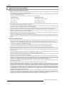 10
10
-
 11
11
-
 12
12
-
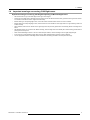 13
13
-
 14
14
-
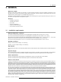 15
15
-
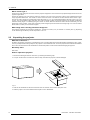 16
16
-
 17
17
-
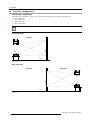 18
18
-
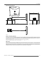 19
19
-
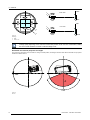 20
20
-
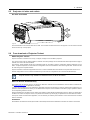 21
21
-
 22
22
-
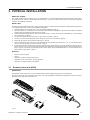 23
23
-
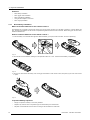 24
24
-
 25
25
-
 26
26
-
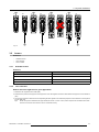 27
27
-
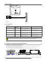 28
28
-
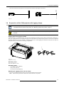 29
29
-
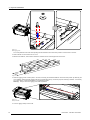 30
30
-
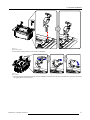 31
31
-
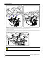 32
32
-
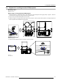 33
33
-
 34
34
-
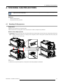 35
35
-
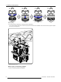 36
36
-
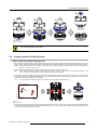 37
37
-
 38
38
-
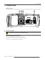 39
39
-
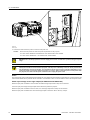 40
40
-
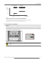 41
41
-
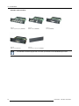 42
42
-
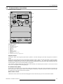 43
43
-
 44
44
-
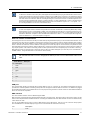 45
45
-
 46
46
-
 47
47
-
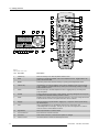 48
48
-
 49
49
-
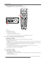 50
50
-
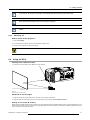 51
51
-
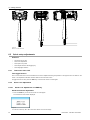 52
52
-
 53
53
-
 54
54
-
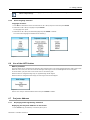 55
55
-
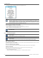 56
56
-
 57
57
-
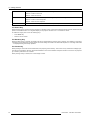 58
58
-
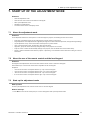 59
59
-
 60
60
-
 61
61
-
 62
62
-
 63
63
-
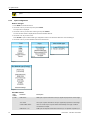 64
64
-
 65
65
-
 66
66
-
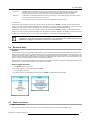 67
67
-
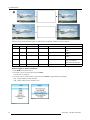 68
68
-
 69
69
-
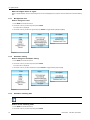 70
70
-
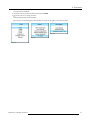 71
71
-
 72
72
-
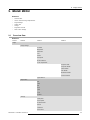 73
73
-
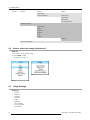 74
74
-
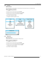 75
75
-
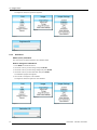 76
76
-
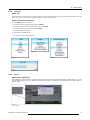 77
77
-
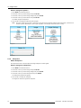 78
78
-
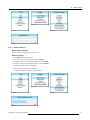 79
79
-
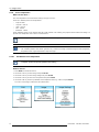 80
80
-
 81
81
-
 82
82
-
 83
83
-
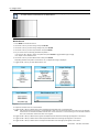 84
84
-
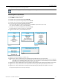 85
85
-
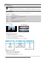 86
86
-
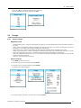 87
87
-
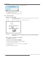 88
88
-
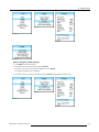 89
89
-
 90
90
-
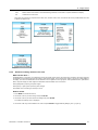 91
91
-
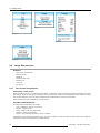 92
92
-
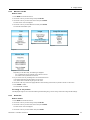 93
93
-
 94
94
-
 95
95
-
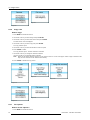 96
96
-
 97
97
-
 98
98
-
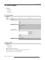 99
99
-
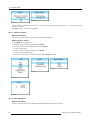 100
100
-
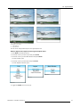 101
101
-
 102
102
-
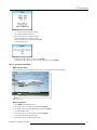 103
103
-
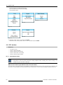 104
104
-
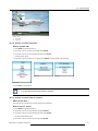 105
105
-
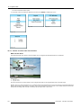 106
106
-
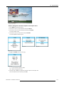 107
107
-
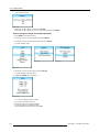 108
108
-
 109
109
-
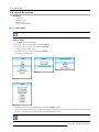 110
110
-
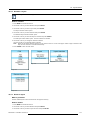 111
111
-
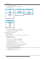 112
112
-
 113
113
-
 114
114
-
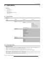 115
115
-
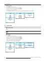 116
116
-
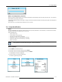 117
117
-
 118
118
-
 119
119
-
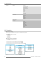 120
120
-
 121
121
-
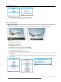 122
122
-
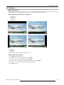 123
123
-
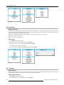 124
124
-
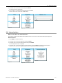 125
125
-
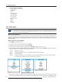 126
126
-
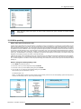 127
127
-
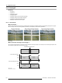 128
128
-
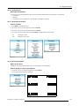 129
129
-
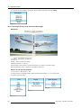 130
130
-
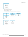 131
131
-
 132
132
-
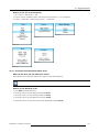 133
133
-
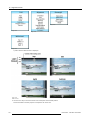 134
134
-
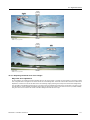 135
135
-
 136
136
-
 137
137
-
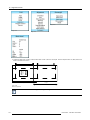 138
138
-
 139
139
-
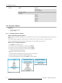 140
140
-
 141
141
-
 142
142
-
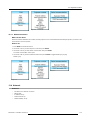 143
143
-
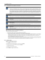 144
144
-
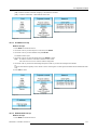 145
145
-
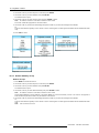 146
146
-
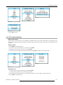 147
147
-
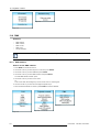 148
148
-
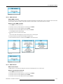 149
149
-
 150
150
-
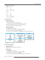 151
151
-
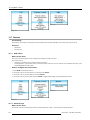 152
152
-
 153
153
-
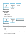 154
154
-
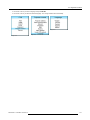 155
155
-
 156
156
-
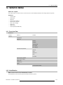 157
157
-
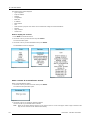 158
158
-
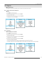 159
159
-
 160
160
-
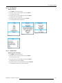 161
161
-
 162
162
-
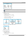 163
163
-
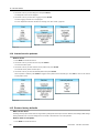 164
164
-
 165
165
-
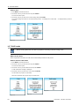 166
166
-
 167
167
-
 168
168
-
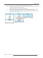 169
169
-
 170
170
-
 171
171
-
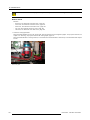 172
172
-
 173
173
-
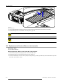 174
174
-
 175
175
-
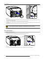 176
176
-
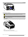 177
177
-
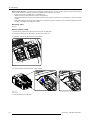 178
178
-
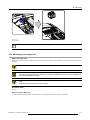 179
179
-
 180
180
-
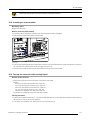 181
181
-
 182
182
-
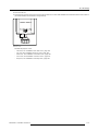 183
183
-
 184
184
-
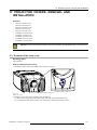 185
185
-
 186
186
-
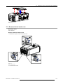 187
187
-
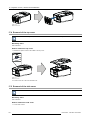 188
188
-
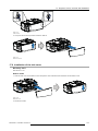 189
189
-
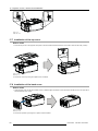 190
190
-
 191
191
-
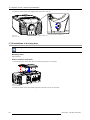 192
192
-
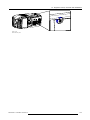 193
193
-
 194
194
-
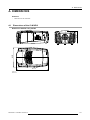 195
195
-
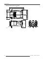 196
196
-
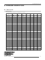 197
197
-
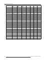 198
198
-
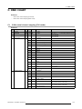 199
199
-
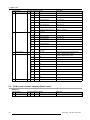 200
200
-
 201
201
-
 202
202
-
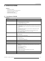 203
203
-
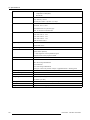 204
204
-
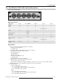 205
205
-
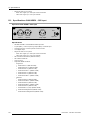 206
206
-
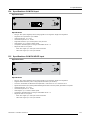 207
207
-
 208
208
-
 209
209
-
 210
210
-
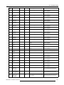 211
211
-
 212
212
-
 213
213
-
 214
214
-
 215
215
-
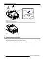 216
216
-
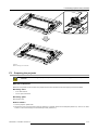 217
217
-
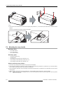 218
218
-
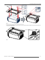 219
219
-
 220
220
-
 221
221
-
 222
222
-
 223
223
-
 224
224
-
 225
225
-
 226
226
-
 227
227
-
 228
228
-
 229
229
-
 230
230
-
 231
231


Barco CLM HD8 User manual
- Category
- Data projectors
- Type
- User manual
Ask a question and I''ll find the answer in the document
Finding information in a document is now easier with AI
Related papers
Other documents
-
Hitachi CP-WU13K User manual
-
-
Texas Instruments U5-112 User manual
-
PLUS Vision PLUS U4-131 User manual
-
PLUS Vision U4-112 User manual
-
-
Lian Li FAN SL-INF 120 Installation guide
-
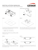 CAYMON CASY 028/B Installation guide
-
Runco CRT Television DTV-940/943 User manual
-
Hitachi CP-DX300 guide User manual
