Page is loading ...

PS360L/PS360WB-L Tandem
PS360/PS360WB Double Tandem
PS360U/PS360WB-U Tri Tandem
PS360U/PS360WB-U Quad Tandem
owner's
operating
& installation
manual
SERIES PS360/360WB
TANDEM GAS OVEN MODELS
A MIDDLEBY COMPANY
© 1998 Middleby Marshall Inc.
Part No. 38615
Price US $30.00
R. Aug. 98, Rev. B, Ver. 3
PS360/360WB Tandem Gas Ovens: English

NOTICE:
This Operating and Installation Manual should be given to the user. The operator of the oven should be
familiar with the functions and operation of the oven.
This manual must be kept in a prominent, easily reachable location near the oven.
The oven has a combustion system suitable for use with all natural gases and can be converted by a
qualified service agent for use with liquified gas.
It is suggested to obtain a service contract with a manufacturer's certified service agent.
WARNING
POST, IN A PROMINENT LOCATION, THE EMERGENCY TELEPHONE NUMBER OF YOUR LOCAL GAS
SUPPLIER AND INSTRUCTIONS TO BE FOLLOWED IN THE EVENT YOU SMELL GAS.
Instructions to be followed in the event the user smells gas shall be obtained by consulting the local gas
supplier. If the smell of gas is detected, immediately call the emergency phone number of your local Gas
Company. They will have personnel and provisions available to correct the problem.
i
Retain This Manual For Future Reference
NOTICE
CONTACT YOUR LOCAL SERVICE COMPANY TO PERFORM MAINTENANCE AND REPAIRS.
A SERVICE AGENT DIRECTORY IS SUPPLIED IN YOUR INSTALLATION KIT.
NOTICE
Using any parts other than genuine Middleby Marshall factory
manufactured parts relieves the manufacturer of all warranty and liability.
NOTICE
Middleby Marshall (Manufacturer) reserves the right to
change specifications at any time.
NOTICE
The equipment warranty is not valid unless the oven is installed, started and demonstrated under
the supervision of a factory certified installer.
WARNING:
Improper installation, adjustment, alteration, service or
maintenance can cause property damage, injury or
death. Read the installation, operating and maintenance
instructions thoroughly before installing or servicing
this equipment.
FOR YOUR SAFETY
Do not store or use gasoline or other
flammable vapors or liquids in the
vicinity of this or any other appliance.

Middleby Marshall Inc. 1400 Toastmaster Drive Elgin, IL 60120 USA (847) 741-3300 FAX (847) 741-4406
Middleby Corporation 24-hour Service Hotline 1-800-238-8444
www.middleby.com
MIDDLEBY MARSHALL INC.
OVEN LIMITED WARRANTY
(Non U.S.A.)
The seller warrants equipment manufactured by it to be free
from defects in material and workmanship for which it is
responsible. The Sellers obligation under this warranty shall
be limited to replacing or repairing at Sellers option, without
charge, F.O.B. Sellers factory, any part found to be defective
and any labor and material expense incurred by Seller in
repairing or replacing such part, such warranty to be limited to
a period of one year from date of original installation or 15
months from date of shipment from Sellers factory, whichever
is earlier, provided that terms of payment have been fully met.
All labor shall be performed during regular working hours.
Overtime premium will be charged to the Buyer.
This warranty is not valid unless equipment is installed,
started, and demonstrated under the supervision of a
factory certified installer.
Normal maintenance functions, including lubrication, adjust-
ment of airflow, thermostats, door mechanisms, microswitches,
burners and pilot burners and replacement of light bulbs, fuses
and indicating lights, are not covered by warranty.
Any repairs or replacements of defective parts shall be per-
formed by Sellers authorized service personnel. Seller shall
not be responsible for any costs incurred if the work is per-
formed by other than Sellers authorized service personnel.
When returning any part under warranty, the part must be intact
and complete, without evidence of misuse or abuse, freight
prepaid.
Seller shall not be liable for consequential damages of any kind
which occur during the course of installation of equipment, or
which result from the use or misuse by Buyer, its employees or
others of the equipment supplied hereunder, and Buyers sole
and exclusive remedy against Seller for any breach of the
foregoing warranty or otherwise shall be for the repair or
replacement of the equipment or parts thereof affected by such
breach.
The foregoing warranty shall be valid and binding upon Seller
if and only if Buyer loads, operates and maintains the equip-
ment supplied hereunder in accordance with the instruction
manual provided to Buyer. Seller does not guarantee the
process of manufacture by Buyer or the quality of product to be
produced by the equipment supplied hereunder and Seller
shall not be liable for any prospective or lost profits of Buyer.
THE FOREGOING WARRANTY IS EXCLUSIVE AND IN LIEU
OF ALL OTHER EXPRESS AND IMPLIED WARRANTIES
WHATSOEVER. SPECIFICALLY THERE ARE NO IMPLIED
WARRANTIES OF MERCHANTABILITY OR OF FITNESS
FOR A PARTICULAR PURPOSE.
The foregoing shall be Sellers sole and exclusive obligation
and Buyers sole and exclusive remedy for any action, whether
in breach of contract or negligence. In no event shall seller be
liable for a sum in excess of the purchase price of the item.
ii

iii
NOTE
Wiring Diagrams Are Contained In This Manual
And Are Also Located Inside The Control Box Door.
TABLE OF CONTENTS
page
SECTION 1 - DESCRIPTION
OVEN SPECIFICATION CHARTS ............................ 1-1
CHART OF ORIFICE SIZES, GAS PRESSURES,
NOMINAL INPUT RATINGS & GAS FLOW ....... 1-1
I. PRINCIPLE OF AIR FLOW ................................. 1-2
A. Heat Transfer And How It Works ................ 1-3
B. Air Fingers ................................................... 1-4
II. COMPONENT FUNCTION ................................. 1-5
A. Conveyor ..................................................... 1-5
B. Gas Burner.................................................. 1-5
C. Front Window .............................................. 1-5
D. Cooling Fans .............................................. 1-6
E. Blower ......................................................... 1-6
F. Air Fingers ................................................... 1-7
SECTION 2 - INSTALLATION
I. UNLOADING/UNPACKING ................................ 2-1
II. INSTALLATION, PREPARATION & SUPPLY ..... 2-2
III. VENTILATION SYSTEM ...................................... 2-3
INSTALLATION KIT .................................................. 2-4
DIMENSION DRAWINGS ......................................... 2-5
IV. THERMOCOUPLE INSTALLATION .................. 2-11
V. ASSEMBLY ....................................................... 2-13
GAS OVEN ROUGH-IN ........................................... 2-21
VI. ELECTRICAL CONNECTION .......................... 2-22
VII. GAS SUPPLY FOR GAS HEATED OVENS ...... 2-24
VIII. PREPARATION FOR VARIOUS GASES ........... 2-25
IX. CHANGING ORIFICES ..................................... 2-27
X. VOLUMETRIC METHOD .................................. 2-27
XI. VAR. OF RATED SUPPLY PRESSURES ......... 2-28
SECTION 3 - OPERATION
I. CONTROL FUNCTIONS .................................... 3-1
II. COMPONENT INFORMATION/LOCATION ........ 3-2
A. Door Safety Switch ...................................... 3-2
B. Blower Switch ............................................. 3-2
C. Heat Switch ................................................. 3-2
D. Temperature Controller .............................. 3-2
E. Conveyor Switch ......................................... 3-3
III. STEP BY STEP OPERATION ............................. 3-4
A. Start-Up Procedure ..................................... 3-4
B. Temp. Controller Operation Inst. ................ 3-5
C. Shutdown Procedure ................................ 3-10
D. Products Baked/Cooked in Ovens ........... 3-10
E. Bake Time vs. Bake Temperature ............ 3-11
F. Conveyor Speed (Bake Time) and
Time of Delivery ........................................ 3-12

TABLE OF CONTENTS
SECTION 4 - MAINTENANCE
I. MAINTENANCE - DAILY ..................................... 4-1
A. Exterior ........................................................ 4-1
B. Fans and Grills ........................................... 4-1
C. Conveyor Belts ............................................ 4-2
D. Crumb Pans ............................................... 4-2
E. Window ....................................................... 4-3
II. MAINTENANCE - MONTHLY .............................. 4-4
A. Removing Conveyor From Oven
For Cleaning ............................................... 4-4
B. Air Fingers Disassembly For Cleaning ...... 4-6
C. Air Finger Reassembly ............................... 4-8
D. Checking Conveyor Belt Tension ............. 4-10
E. Conveyor Belt Link Removal ..................... 4-10
F. Conveyor Reinstallation Into Oven ........... 4-12
III. MAINTENANCE - EVERY 3 MONTHS .............. 4-13
A. Cleaning Blower Motors ........................... 4-13
B. Electrical Terminals .................................. 4-13
IV. MAINTENANCE - EVERY 6 MONTHS .............. 4-14
SECTION 5 - TROUBLESHOOTING
OWNERS TROUBLESHOOTING CHARTS .............. 5-1
SECTION 6 - ELECTRICAL SCHEMATICS
Wiring Diagram -
Tandem/Double Tandem Ovens ....................... 6-2
Wiring Diagram -
Tri Tandem/Quad Tandem Ovens ..................... 6-3
Schematic - PS360/360WB Tandem (All Models) .... 6-4
iv

NOTES:
v

1-1
SECTION 1
DESCRIPTION
OVEN INFORMATION (per oven section)
PS360 PS360WB
Weight, Single Oven 1350 lbs. (612kg) 1400 lbs. (634kg)
Shipping Weight, Single Oven 1675 lbs. (760 kg) 1750 lbs. (780kg)
Shipping Cube, Single Oven Approx. 104.5 ft
3
(3.0 m
3
) Approx. 122 ft.
3
(3.5m
3
)
Rated Heat Input 135,000 BTU (34,020 kcal, 40 kW/hr) 170,000 BTU (42,840 kcal, 50 kW/hr)
Maximum Operating Temperature 550°F (288°C)
Flue Vent 1.08" (27mm) D x 3" (76mm) W
Exhaust Flow, Single Oven 80 ft.
3
/min. (2.1 m
3
/min.)
Warm Up Time 10 min.
For oven dimensions, gas information, and electrical information, refer to the Installation section.
SECTION 1
DESCRIPTION
CHART OF ORIFICE SIZES, GAS PRESSURES, NOMINAL INPUT RATINGS AND GAS FLOW
IMPORTANT: This chart is not for use in Germany.
Orifice Diameter (mm) Gas Pressures (mbar) Nominally Low Gas Gas
Oven Category Gas Main By-Pass Pilot Supply Orifice Input Flame Supply Flow
Model Type (Full (Low (Inlet) (Manifold) (kW) (kW) Volume (liter/min.)
Flame) Flame)
Natural, E(H) 5.5 1.65 0.64 20 8 4.2 m
3
/h 70.0
PS360L I
2E+
Natural, LL(L) 5.5 1.65 0.64 20 12.5 4.9 m
3
/h 81.7
& Natural,E(H)/LL(L) 4.5 1.50 0.64 20/25 * 40 4.4 4.2/4.9 70.0/81.
PS360U II
2H3+
Liquid, G30 2.7 0.85 0.38 50 * 3.1 kg/h
Liquid,G31/G30 3.1 0.95 0.38 30/37 * 3.1 kg/h
Natural, H 6.3 2.30 0.64 20 8.7 5.3 m
3
/h 88.0
PS360WB-L II
2E+3+
Natural, L 6.3 2.30 0.64 20 12 6.1 m
3
/h 102.4
Natural,G20/G25 5.4 2.00 0.64 20/25 17/22 50 8.8 5.3/6.1 88.0/102.4
PS360WB-U II
2L3B/P
Liquid, G30 3.1 1.40 0.38 50 * 3.9 kg/h --
Liquid, G30/G31 3.5 1.40 0.38 30/37 * 3.9 kg/h --
*Pressure regulator (Governor) not in operation, system at inlet (supply) pressure.
The orifice pressures apply to 15°C, 1.013 mbar, dry gas.

1-2
SECTION 1
DESCRIPTION
1
2
4
3
4
3
2
3
I. PRINCIPLE OF AIR FLOW
Air is heated in the heating chamber (1), then pulled into the
impellers or blowers (2), which push the air into the oven
plenum and delivers the heated air into the air fingers (3). The
fingers contain an inner plate and outer plate which columnate
the air and evenly distribute the heated air across the conveyor
belt (4) on which the product rides. The air is then pulled back
into the heating chamber (1) and the process continues.
Refer to next page for another illustration of the oven air fingers.
Figure 1-3 - AIR DELIVERY SYSTEM
(per oven section)

1-3
SECTION 1
DESCRIPTION
Figure 1-4. Air Fingers Showing Air Passing Through
Inner Plate And Outer Plate Which Forms High Velocity
Columns Of Air To Product.
Inner Plate
Outer Plate
Inner Plate
Air Flow From Plenum
Chamber
Air Flow From Plenum
Chamber
High Velocity Columns
of Air to Product
Outer Plate
A. Heat Transfer and How It Works
1. Heat constantly moves from a warm object to a cold object.
Heat moves using three different paths which are conduction,
radiation and convection.
Conduction: This path has to do with surface to surface
contact. The pizza dough in contact with the pan is a good
example of conduction.
Radiation: This path has to do with objects radiating heat.
Dark objects absorb heat whereas light or shiny objects reflect
more heat. Because of this, the inside of the oven is light in
color, reflecting more heat back to the product.
Convection: This path has to do with moving amounts of air.
It explains why hot air will rise and cooler air replaces hot air.
An industrial application of this principle is to incorporate a fan
to force the hot air movement which in turn will increase the heat
transfer to the product.
The oven has two large blowers to move the hot air through the
air fingers and onto the product so the most efficient bake is
achieved.
Temperature is the intensity of heat at the point which it is
sensed. As discussed above, heat flows by conduction, radia-
tion and convection. The speed at which the heat flows is
determined by the temperature difference between the oven
and the food product. The larger the difference, the faster the
heat flows to the item that is being baked.

1-4
SECTION 1
DESCRIPTION
B. Air Fingers
The Middleby Marshall ovens are heavy duty conveyorized hot
air ovens employing vertical air streams (Figure 1-3 and 1-4) to
give uniform and intensive heating. The columnated vertical
streams of hot air provide an exceptional heat transfer rate and
generally bake faster and at lower temperatures than convec-
tion hot air or infrared heating ovens.
This is accomplished by the hot air fingers, (Figure 1-3 and 1-
4) inside the oven. The oven can accommodate up to 6 bottom
air fingers and 6 top air fingers. Standard ovens have 5 bottom
fingers and 3 top fingers.
Figure 1-5. Component Location
Removable
Conveyor
Front Loading
Windows
Removable
Crumb
Pans
Removable
End Panels
Oven Data
Plate
Control
Panel
Machinery
Compartment
Access Panel
Conveyor
Extensions
Conveyor
Motor
Removable
Jet Fingers

1-5
SECTION 1
DESCRIPTION
II. COMPONENT FUNCTION
The components for the lower and upper ovens are identical.
The following description covers the lower oven.
A. Conveyor
The conveyor is driven by a direct current electric motor
operating through a gear reducer, (See Figure 1-6). The motor
speed is controlled by a digital control. The stainless steel
wire belt can travel in either direction and at variable speeds.
Note that only one oven section will control the speed of the
conveyor (2 for a double tandem oven).
B. Gas Burner
Turning the heat switch to "I" will initially set up the oven purge
circuit. After approximately 45 seconds, the solid-state ignition
control lights a pilot by an electric spark.
After the pilot is lit, the main valve will open, permitting gas to go
to the burner and heat the oven.
The main burner and pilot gas are extinguished when heat is off.
This system permits the main gas valve to open only when the
pilot burner is proven to be lit.
If the pilot flame does not light or a loss of flame occurs, the main
valve closes and the red lamp is lit on the "RESET" switch. The
"RESET" switch must be pushed to restart the ignition
sequence.
Note that the gas burner of each oven section is independently
controlled by that section's temperature controller.
C. Front Window
A front window provides access to each section of the oven for
items which do not require full bake time, such as sandwiches,
cookies, small items or cheese melting processes.
The window is also used for viewing items being baked and
for cleaning.
Figure 1-6. Conveyor Drive Motor

1-6
SECTION 1
DESCRIPTION
D. Cooling Fans -- See Figure 1-7
There are two cooling fans located in the back of each oven.
These fans blow cool air in through the machinery compartment,
across the blower motors, and out the rear of the top cover, or
out the front bottom of the lower oven.
E. Blower
A blower is located in each end of each oven section. These
blowers force heated air through the oven and fingers. The
blower switch has two positions, and must be on for oven
warmup and bake.
Figure 1-7. Cooling Fans

1-7
SECTION 1
DESCRIPTION
F. Air Fingers
The Air Finger Assemblies are made up of three parts as
follows (See Figure 1-8):
1. Outer Plate-The Outer Plate is the removable covering with
tapered holes, which directs the air stream onto the product to
be baked. Outer plates are manufactured with 1 row of holes (L1
finger), 3 rows of holes (L3 finger), 6 rows of holes (L6 finger) or
no holes (a radiant finger).
2. Inner Plate -The Inner Plate directs air through the air finger,
and is vital to forming the unique air jets.
3. Finger Manifold-The Finger Manifold is the assembly which
slides on tracks into the oven plenum. Blank plates are available
to install on the plenum where an air finger is not required. The
finger manifold contains one non-adjustable baffle, as shown in
Figure 1-8.
Figure 1-8. Fingers

1-8
SECTION 1
DESCRIPTION
NOTES:

2-1
SECTION 2
INSTALLATION
WARNING
Do not obstruct the flow of combustion
and ventilation air to and from your
oven. There must be no obstructions
around or underneath the oven.
I. UNLOADING/UNPACKING
Your Middleby Marshall Ovens are shipped partially assembled.
Each oven section will arrive in its own crate of the following
size and weight:
PS360U/PS360L PS360WB-U/PS360WB-L
Length: 72 (183cm) 66 (167cm)
Width: 48 (122cm) 57 (144cm)
Height: 60 (152cm) 50 (127cm)
Weight: 1675 lbs. (760kg) 1750 lbs. (780kg)
If you ordered stands for your ovens, they are shipped in
separate crates.
When your common carrier or truck line notifies you of delivery,
you must have a forklift at the facility to unload the crate(s).
If you have a door that is wider than the ovens, simply move the
ovens into your facility and set up an appointment with your
Middleby Marshall Authorized Installer.
NOTE: The width of each oven can be reduced by about 1"
(25mm) by removing the window from the oven. Window
disassembly instructions are in the Cleaning section of this
Owners Manual.
If the ovens are wider than your door opening, the oven will
have to be dismantled according to the directions in the Pre-
Installation Procedures Manual.
SECTION 2
INSTALLATION
NOTE
There must be adequate clearance
between the oven and combustible con-
struction. Clearance must also be pro-
vided for servicing and for
operation.
WARNING
This oven must be installed in accordance
with the rules in force. Use only in a
well ventilated area. Read the
instructions before use.

2-2
SECTION 2
INSTALLATION
2"
51mm
Minimum
18"
458mm
18"
458mm
12"
305mm
3”
76mm
II. INSTALLATION, PREPARATION, AND
SUPPLY
When preparing the oven for installation at a location, the latest
International, National or Local Requirements should be
adhered to.
The ovens must be installed on an even (level) non-flammable
flooring and any adjacent walls must be non-flammable. The
minimum allowed distance from the rear of the oven to the wall
is 12 (30cm).
The ovens can be supported only by legs. No casters are
allowed. It should be made certain that there are no obstructions
located around or underneath the oven that interfere with air
circulation.
The ovens must be installed under a ventilating hood with
electrical exhaust air sensing control.
The gas supply connection should be according to applicable
ISO-228-1 or ISO-7-1 recommendations.
Normally, the oven is preparted and adjusted to the specific
gas type used by the customer. Before operating the oven,
check the label on the oven and also on the packaging that the
gas type indicated matches the local supply at the installation.
If not, refer to Section VI, PREPARATION FOR VARIOUS
GASES, in this chapter and convert as directed.
All installations, conversions and service work must be
performed by an Authorized Service Agent according to the
instructions supplied by the manufacturer.
When converting from one gas type to a different type, the
orifices supplied with the conversion kit must be checked for
proper size as specified in this manual to assure that the oven
is operating at the nominal rated input.
Figure 2-1 - Ventilation Hood Dimensions (RECOMMENDATIONS ONLY)

2-3
SECTION 2
INSTALLATION
III. VENTILATION SYSTEM
IMPORTANT
Where international, national, or local codes require
the installation of fire suppression equipment or other
supplementary equipment, DO NOT mount the
equipment directly to the oven.
MOUNTING SUCH EQUIPMENT ON THE OVEN MAY:
VOID AGENCY CERTIFICATIONS
RESTRICT SERVICE ACCESS
LEAD TO INCREASED SERVICE EXPENSES FOR
THE OWNER
REQUIREMENTS
A mechanically driven ventilation system is required for the
oven.
PROPER VENTILATION OF THE OVEN IS THE
RESPONSIBILITY OF THE OWNER.
RECOMMENDATIONS
NOTE THAT THE HOOD DIMENSIONS SHOWN IN FIG-
URE 2-1 (PREVIOUS PAGE) ARE
RECOMMENDATIONS
ONLY. INTERNATIONAL, NATIONAL, AND LOCAL
CODES WILL VARY, AND MUST BE FOLLOWED WHEN
INSTALLING THE VENTILATION SYSTEM. ANY AP-
PLICABLE INTERNATIONAL, NATIONAL, AND LOCAL
CODES SUPERSEDE THE RECOMMENDATIONS
SHOWN IN THIS MANUAL.
The rate of air flow exhausted through the ventilation system
may vary depending on the oven configuration and hood
design. Consult the hood manufacturer or ventilation engineer
for these specifications.
To avoid a negative pressure condition in the kitchen area,
return air must be brought back to replenish the air that was
exhausted. A negative pressure in the kitchen can cause heat-
related problems to the oven components as if there were no
ventilation at all. The best method of supplying return air is
through the heating, ventilation and air conditioning (HVAC)
system. Through the HVAC system, the air can be temperature-
controlled for summer and winter. Return air can also be
brought in directly from outside the building, but detrimental
affects can result from extreme seasonal hot and cold
temperatures from the outdoors.
NOTE: Return air from the mechanically driven system
must
not blow at opening of bake chamber. Poor oven baking
performance will result.
OTHER VENTILATION CONCERNS
Special locations, conditions, or problems may require the
services of a ventilation engineer or specialist.
Inadequate ventilation can inhibit oven performance.
It is recommended that the ventilation system and duct
work be checked at prevailing intervals as specified by the
hood manufacturer and/or HVAC engineer or specialist.

2-4
SECTION 2
INSTALLATION
PS360L/WB-L Tandem
PS360/WB Double Tandem
PS360U/WB-U Tri Tandem
Item Part # Description PS360U/WB-U Quad Tandem
1 22361-0001 Flexible Gas Hose 2 4 3 4
2 22450-0028 Adjustable Legs 8 8 12 16
3 30773 Flue Vent, 14"Lg. 2 - - -
4 30759 Flue Vent, 29-1/2"Lg. - 2 3 4
5 30758 Flue Vent, 50" Lg. - 2 - -
6 21256-0008 Screw, 10-32 x 3/8 A/R A/R A/R A/R
8 42400-0089 Master Link Kit, PS360
8 42400-0598 Master Link Kit, PS360WB
9 35122-0049 Attachment Strip - 4 - -
10 35000-1103 Stop, End Conv., PS360
10 35000-1899 Stop, End Conv., PS360WB
11 21292-0001 Scr, #2PT 10-16 x 3/4 Hx Wsh A/R A/R A/R A/R
12 33984 Thermocouple 2 4 3 4
13 27276-0001 Cable Clamp 2 4 3 4
14 1002040 Warranty,Parts & Serv. Dist.List 1 1 1 1
15 38615 Owners Manual,English 1 1 1 1
16 27126-0238 11 Piece Hex Key Set 1 1 1 1
17 31389 Silicone Tubing, 36 (914mm) L x
5/16 (8mm) ID x 7/16 (11mm) OD 2 4 3 4
- 35000-1454
Machinery Compartment Trim Strip
1222
- 35000-1456 Front Gasket Spacer 2 4 4 4
- 35000-1457 Rear Gasket Spacer 2 4 4 4
- 37200-0013
Baking Chamber Gasket and Frame
1222
- 37000-0696 Transition Floor Panel - - - 1
- 48009-0024 Transition Top Panel - - - 1
- 48009-0025 Transition Side Wall - - - 2
- 35000-1748 Transition Rear Support - - - 1
- 35000-1749 Transition Front Support - - - 2
- 37000-0697 Transition Top Support Channel - - - 2
2434
12 --
Figure 2-2 - INSTALLATION KIT

2-5
SECTION 2
INSTALLATION
6”
152mm
10-1/2”
267mm
16-1/2"
419mm
11-1/2"
292mm
27-1/4"
692mm
27-1/4"
692mm
54-1/2"
1384mm
17-3/4"
451mm
31-1/2"
800mm
45-1/2"
1156mm
144-1/2"
3670mm
109"
2769mm
17-3/4"
451mm
42"
1067mm
40"
1016mm
6-1/2"
165mm
45"
1143mm
42-3/4"
1086mm
4
4
1
2
1
2
2”
51mm
3
32”
813mm
16-1/2"
419mm
11-1/2"
292mm
27-1/4"
692mm
27-1/4"
692mm
54-1/2"
1384mm
6”
152mm
10-1/2”
267mm
31-1/2"
800mm
6-1/2"
165mm
45-1/2"
1156mm
144-1/2"
3670mm
109"
2769mm
17-3/4"
451mm
17-3/4"
451mm
50-3/4”
1289mm
50"
1270mm
48"
1219mm
53"
1346mm
4
4
1
2
1
2
2”
51mm
3
40”
1016mm
Figure 2-3
Dimensions and Data: PS360L Tandem
Figure 2-4
Dimensions and Data: PS360WB-L Tandem

2-6
SECTION 2
INSTALLATION
34"
864mm
16-1/2"
419mm
11-1/2"
292mm
27-1/4"
692mm
27-1/4"
692mm
54-1/2"
1384mm
5-27/32"
148mm
10-1/8"
258mm
6-1/4"
158mm
11-1/2"
292mm
31-1/2"
800mm
6-1/2"
165mm
144-1/2"
3670mm
109"
2769mm
17-3/4"
451mm
17-3/4"
451mm
52"
1321mm
81-1/2"
2070mm
2”
51mm
42"
1067mm
40"
1016mm
45"
1143mm
3
4
4
13
1
2
1
2
1
2
1
2
32”
813mm
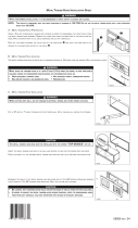
Figure 2-5
Dimensions and Data: PS360 Double Tandem
Figure 2-6
Dimensions and Data: PS360WB Double Tandem
/