Page is loading ...

HX600S
HX600S
VHF/FM Marine Handheld Transceiver
Owner's Manual

HX600S
TABLE OF CONTENTS
RF EXPOSURE SAFETY STATEMENT ........................................................................................ 2
FCC AND CANADA RADIO LICENSE INFORMATION ............................................................... 3
FCC NOTICE .................................................................................................................................. 4
1. GENERAL INFORMATION ........................................................................................................ 5
1.1 INTRODUCTION ................................................................................................................. 5
2. ACCESSORIES .......................................................................................................................... 6
2.1 PACKING LIST ..................................................................................................................... 6
2.2 OPTIONS ............................................................................................................................. 6
3. ABOUT THIS RADIO .................................................................................................................. 7
3.1 ABOUT THE VHF MARINE BAND ...................................................................................... 7
3.2 ABOUT RECEIVE ONLY CHANNELS AND FREQUENCIES ............................................ 7
4. GETTING STARTED .................................................................................................................. 9
4.1 BATTERIES AND CHARGERS ........................................................................................... 9
4.2 CONNECTING A GPS TO THE CD-36 ........................................................................... 13
5. CONTROLS AND SWITCHES ................................................................................................. 14
6. BASIC OPERATION ................................................................................................................. 1 8
6.1 INITIAL SETUP ................................................................................................................. 18
6.2 RECEPTION ..................................................................................................................... 18
6.3 TRANSMISSION ............................................................................................................... 19
6.4 NOAA WEATHER CHANNELS ........................................................................................ 20
6.5 PRESET CHANNELS (0 ~ 9) .......................................................................................... 23
6.6 ENABLING S.O.S STROBE OPERATION ....................................................................... 23
7. ADVANCED OPERATION ON THE MARINE BAND ................................................................ 24
7.1 USA, CANADA, AND INTERNATIONAL CHANNELS ..................................................... 24
7.2 MEMORY SCAN ................................................................................................................ 24
7.3 PROGRAMMABLE PRIORITY SCAN .............................................................................. 25
7.4 DUAL WATCH ................................................................................................................... 26
7.5 TRI WATCH ....................................................................................................................... 26
7.6 EMERGENCY CHANNEL 16 ........................................................................................... 26
7.7 CHANNEL 9 ...................................................................................................................... 27
7.8 OPERATING ON USA or CANADIAN 13, OR USA CHANNEL 67 ................................. 27
7.9 OPERATING ON USA CHANNEL 67 .............................................................................. 27
7.10 DIGITAL SELECTIVE CALLING..................................................................................... 28
7.11 SIMPLEX/DUPLEX CHANEL USE ................................................................................ 2 9
8. SCRAMBLER OPERATION ..................................................................................................... 30
8.1 VOICE SCRAMBLER UNIT .............................................................................................. 30
9. OPERATING PRACTICE .......................................................................................................... 30
9.1 EMERGENCY (CHANNEL 16 USE) ............................................................................... 30
9.2 CALLING ANOTHER VESSEL (CHANNEL 16 OR 9) .................................................... 31
9.3 OPERATING ON CHANNEL 13 AND 67 ......................................................................... 32
9.4 NOAA WEATHER ALERT TESTING ................................................................................ 32
10. MENU (“SET”) MODE ...........................................................................................................33
11. INSTALLATION OF OPTIONS ............................................................................................... 3 7
11.1 FVP-31 VOICE SCRAMBLER UNIT .............................................................................. 37
11.2 FBA-25A ALAKLINE BATTERY TRAY ............................................................................ 37
12. MAINTENANCE ...................................................................................................................... 38
12.1 GENERAL ....................................................................................................................... 38
12.2 REPLACEMENT PARTS ................................................................................................ 38
12.3 TROUBLESHOOTING CHART .................................................................................... 39
13.VHF MARINE CHANNEL ASSIGNMENT ................................................................................ 40
14. WARRANTY ........................................................................................................................... 4 6
15. SPECIFICATIONS .................................................................................................................. 50

HX600S Page 1
Congratulations on your purchase of the HX600S! Whether this is your first
portable marine VHF transceiver, or if you have other STANDARD HORIZON
equipment, the STANDARD HORIZON organization is committed to ensur-
ing your enjoyment of this high performance transceiver, which should pro-
vide you with many years of satisfying communications even in the harshest
of environments. STANDARD HORIZON technical support personnel stands
behind every product sold, and we invite you to contact us should you re-
quire technical advice or assistance.
We appreciate your purchase of the HX600S, and encourage you to read
this manual thoroughly, so as to learn and fully understand the capabilities of
the HX600S.
WARNING
This radio is capable of transmitting on VHF Marine.
The FCC allows the use of VHF Marine band on water areas only. How-
ever the FCC does not allow the use of the VHF Marine band when on
land. If persons use the VHF Marine Band on land and interfere with
others communicating, the FCC will be notified and search for the inter-
ference. Responsible parties found to be transmitting on the VHF Ma-
rine Band on land could be fined up to $10,000 for the first offense.

HX600SPage 2
RF EXPOSURE SAFETY STATEMENT
SAFETY INFORMATION
Your wireless handheld portable transceiver contains a low power trans-
mitter. When the Push-to-Talk (PTT) button is pushed, the transceiver
sends out radio frequency (RF) signals. In August 1996, the Federal
Communications Commission adopted RF exposure guidelines with
safety levels for hand-held wireless devices.
This device is authorized to operate at a duty factor not to exceed 50%
(this corresponds to 50% transmission time and 50% reception time).
WARNING: To maintain compliance with the FCC’s RF exposure guide-
lines, this transmitter and its antenna must maintain a separation dis-
tance of at least 1 inch (2.5 centimeters) from your face. Speak in a
normal voice, with the antenna pointed up and away from the face at the
required separation distance.
If you use a headset accessory for this radio, with the radio worn on your
body, use only the Vertex Standard belt clip for this transceiver, and
ensure that the antenna is at least 1 inch (2.5 centimeters) from your
body when transmitting.
Use only the supplied antenna. Unauthorized antennas, modifications,
or attachments could damage the transmitter, and may violate FCC regu-
lations.
NOTE
This radiotelephone complies with the requirements of RTCM Paper 56-
95/SC101 Standards for digital selective calling (DSC) for Marine trans-
ceivers.

HX600S Page 3
FCC AND CANADA RADIO LICENSE INFORMATION
Standard Horizon radios comply with the Federal Communication Commis-
sion (FCC) and Industry-Canada requirements that regulate the Maritime
Radio Service.
MARITIME STATION LICENSE
An FCC ship station license is no longer required for any vessel traveling in
U.S. waters which uses a VHF marine radio, RADAR or EPIRB, and which is
not required to carry radio equipment. However, any vessel required carry-
ing a marine radio on an international voyage, carrying a HF single side
band radiotelephone or marine satellite terminal. FCC license forms, includ-
ing applications for ship (506) and land station licenses can be downloaded
via the Internet at
www.fcc.gov/forms. To obtain a form from the FCC, call
(888) 225-5322.
MARINE RADIO CALL SIGN
Currently the FCC does not require recreational boaters to have a Ship Ra-
dio Station License. The USCG recommends the boats registration number
and the state to be used.
CANADIAN SHIP STATION LICENSING
You may need a license when traveling in Canada. If you do need a license
contact their nearest field office or regional office or write:
Industry Canada
Radio Regulatory Branch
Attn: DOSP
300 Slater Street
Ottawa, Ontario
Canada, KIA 0C8
FCC/INDUSTRY CANADA INFORMATON
The following data pertaining to the transceiver is necessary to fill out the
license application.
FCC Type Accepted: .......................................................................... Part 80
Output Power with FNB-83: ........... 1 W (Low), 2.5 W (Mid), and 5 W (High)
Emission: ...................................................................... 16K0G3E, 16K0G2B
Frequency Range: .................................................. 156.025 to 163.275MHz
FCC Type Number: ................................................................. K6630193X20
Industry Canada Type Approval: ......................................... 511B-30193X20

HX600SPage 4
FCC NOTICE
Unauthorized changes or modifications to this equipment may void compli-
ance with FCC Rules. Any change or modification must be approved in writ-
ing by STANDARD HORIZON, a Marine Division of VERTEX STANDARD.
NOTICE
This equipment has been tested and found to comply with the limits for a
Class B digital device, pursuant to Part 15 of the FCC Rules. These
limits are designed to provide reasonable protection against harmful in-
terference in a residential installation. This equipment generates uses
and can radiate radio frequency energy and, if not installed and used in
accordance with the instructions, may cause harmful interference to ra-
dio communications. However, there is no guarantee that interference
will not occur in a particular installation. If this equipment does cause
harmful interference to radio or television reception, which can be deter-
mined by turning the equipment off and on, the user is encouraged to try
to correct the interference by one or more of the following measures:
Increase the separation between the equipment and receiver.
Connect the equipment into an outlet on a circuit different from that to
which the receiver is connected.
Consult the dealer or an experienced marine electronics technician
for help.
PROHIBITED COMMUNICATIONS
The FCC prohibits the following communications:
• False distress or emergency messages:
• Messages to “any boat” except in emergencies and radio tests;
• Messages to or from a vessel on land;
• Transmission while on land;
• Obscene, indecent, or profane language (potential fine of $10,000).

HX600S Page 5
1. GENERAL INFORMATION
1.1 INTRODUCTION
The HX600S is a SUBMERSIBLE miniature 5-Watt portable two-way marine
transceiver. The transceiver has all allocated USA, International, or Cana-
dian channels. It has emergency channel 16 which can be immediately se-
lected from any channel by pressing the [16/9] key. NOAA Weather channels
can also be accessed immediately by pressing the [WX] key. In addition to
these functions the HX600S can transmit a Digital Selective Distress Call
with Latitude/Longitude when a GPS is connected to the CD-36 Cradle Charger.
Besides VHF marine transceiver operation, the HX600S provides receive ONLY
coverage of AM, FM broadcast bands and AM aircraft bands.
The HX600S includes the following features: Memory Scanning, Priority Scan-
ning, NOAA Weather Alert, NOAA SAME, Battery Saver, easy-to-read large
LCD display, EEPROM memory back-up, Battery Life displayed on LCD,
Transmit Time-Out Timer (TOT) and a strobe light when enabled blinks the
internationally recognized SOS distress signal.
In the marine band, the transmitter provides a maximum of 5 Watts output,
and has the selection of 2.5 Watts and 1 Watt to assist the user in ensuring
maximum battery life.
The optional FVP-31 Voice Scrambler can be installed to permit secure voice
communications with other Standard Horizon radios with the FVP-31 scram-
blers installed.

HX600SPage 6
2. ACCESSORIES
2.1 PACKING LIST
When the package containing the transceiver is first opened, please check it
for the following contents:
• HX600S Transceiver
• CAT460 Antenna
• FNB-V98LI 7.4 V, 1700 mAh Li-Ion Battery Pack
• CD-36 Charger Cradle for HX600S
• NC-90B 120 VAC Overnight Charger for CD-36
• E-DC-19A DC Cable with 12 V Cigarette Lighter Plug for CD-36
• Owner’s Manual
2.2 OPTIONS
CMP460 Noise-canceling Waterproof
Speaker/Microphone
MH-57A4B Mini Speaker/Microphone
VC-24 VOX Headset
VC-27 Earpiece/Microphone
FVP-31 Voice Scrambler
CD-36 Charger Cradle
FNB-V98LI 7.4 V, 1700mAh Li-Ion Battery Pack
FBA-25A Alkaline Battery Case
E-DC-19A DC Cable with 12 V Cigarette Lighter
Plug
NC-90B/C 120/230 VAC Overnight Charger for
the FNB-V98LI
E-DC-6 DC Cable; plug and wire
only
CAW230 Radio-to-Ship’s-Antenna
Adapter
Note: Before operating the HX600S for the
first time, it is recommended that the bat-
tery be charged. Please see section
4.1.4 “USING THE CD-36 CHARGER
CRADLE” for details.

HX600S Page 7
3. ABOUT THIS RADIO
3.1 ABOUT THE VHF MARINE BAND
WARNING:
The radio frequencies used in the VHF marine band lie
between 156 and 158 MHz with NOAA Weather sta-
tions available between 161 and 163 MHz. The marine
VHF band provides communications over distances
that are essentially “line of sight” Actual transmission range depends much
more on antenna type, gain and height than on the power output of the trans-
mitter. A portable 5W radio transmission expected distance can be greater
than 5 miles “line of sight.”
The user of a Marine VHF radio is subject to severe fines if the radio is
used on land. The reasoning for this is you may be near an inland waterway,
or propagation anomalies may cause your transmission to be heard in a wa-
terway. If this occurs, depending upon the marine VHF channel on which you
are transmitting, you could interfere with a search and rescue case, or contrib-
ute to a collision between passing ships. For VHF Marine channel assign-
ments refer to page 40 section 13.
3.2 ABOUT RECEIVE ONLY CHANNELS and FREQUENCIES
AM/FM Broadcast Bands
The AM/FM bands contained within the HX600S are the same channels you
use every day to listen to music, news and commentary with your car or home
stereo.
The AM broadcast band currently extends from 500 to
1800 kHz. Channels are spaced in even 10 kHz incre-
ments; i.e.: 510, 520, 530, ... , 1800 kHz in the United
States and Canada. Elsewhere, channels are spaced
in 9 kHz increments, i.e.: 504, 513, 522, etc.
The FM broadcast band in the United States extends
from 88 to 108 MHz. Channels are assigned at 100
kHz increments; i.e.: 88.1, 88.2, 88.3, ... , 107.9. The
channels from 88.1 to 91.9 are reserved for noncom-
mercial educational stations. Outside the United States and Canada, the bound-
aries and channel spacing vary. In Japan, the band starts at 76 MHz. In West-
ern Europe, the band generally runs from 88-108 MHz, but channels can be
irregularly spaced, i.e.: 101.25 MHz.

HX600SPage 8
AIR
(
Aircraft
)
BAND FREQUENCY CHART
Frequency Range Communications Usage
108.000 - 117.975 MHz Navigational Aids
118.000 - 121.400 MHz Control Towers
121.500 MHz Int’l Distress Frequency
121.600 - 122.900 MHz Ground & Apron Control
122.700 - 123.900 MHz UNICOM Frequencies
123.450 MHz Air to Air / Pilot chit chat
124.000 - 128.800 MHz Arrivals & Departures
128.825 - 132.000 MHz Company Operations
132.000 - 135.975 MHz Area Control center (Enroute)
136.000 - 136.975 MHz Shared ATC/Company Ops & DataLink
AIR (Aircraft) Bands
The AM VHF aeronautical communications band lies
between 108.000 MHz and 136.975 MHz. This fre-
quency spectrum can be divided into a lower and up-
per range. The lower range between 108.000 MHz and
118.000 MHz is primarily used for navigational aids such as the ILS - Instru-
ment Landing Systems, DME - Distance Measuring Equipment, and VOR’s -
Very High Frequency Omni Range. The lower range offers very little in the way
of voice communications, it does however provide someone with a working
knowledge of Morse code the opportunity to identify various beacons. The up-
per range of the aeronautical band 118.000 MHz to 136.975 MHz is where the
majority of voice communications can be monitored. Communications in the
VHF band are transmitted in AM mode and most if not all compatible receivers
automatically default to this mode. Frequencies within the aeronautical range
are spaced in increments of 25 kHz, as such you will find transmissions at
118.000, 118.025, 118.050 MHz etc.
The frequency(s) you monitor will determine the nature of traffic you will hear.
As previously mentioned frequencies in the lower range of the aeronautical
band are mostly occupied by navigational equipment and transmit non-voice
signals in Morse code. If you select a frequency in the upper range the air is
suddenly filled with conversations between pilots and air traffic controllers,
pilots and their company dispatchers, flight service stations, and ATIS broad-
casts. Frequencies within the aeronautical band are designated according to
their usage.
Refer to page 18 for operation.

HX600S Page 9
4. GETTING STARTED
Lithium ion (Li-ion) batteries pack high energy density in a tiny package. Other
than higher power and lower weight, li-ion batteries are user friendly as well.
Unlike its predecessor, the nickel-cadmium, lithium-ion batteries do not suffer
from the “memory effect.” That is, the battery does not have to be fully dis-
charged before being recharged.
Though the batteries do not suffer from the memory effect, it is just the oppo-
site that users should be wary of. Lithium ion batteries shouldn’t be run all the
way down before charging; they respond much better with constant recharges.
To prolong the battery when not in use, store it in a cool dry place at approxi-
mately 40 percent capacity. Also, avoid exposing a lithium ion battery to ex-
treme temperatures for prolonged periods of time, and recharge constantly
when in use.
4.1 BATTERIES AND CHARGERS
The FNB-V98LI is a high performance Lithium-Ion battery providing high ca-
pacity in a compact package.
CAUTION
To avoid risk of explosion and injury, FNB-V98LI battery pack should only
be removed, charged or recharged in non-hazardous environments.
4.1.1 BATTERY SAFETY
Battery packs for your transceiver contain Lithium-Ion batteries. This type of
battery stores a charge powerful enough to be dangerous if misused or abused,
especially when removed from the transceiver. Please observe the following
precautions:
DO NOT SHORT BATTERY PACK TERMINALS: Shorting the terminals that
power the transceiver can cause sparks, severe overheating, burns, and
battery cell damage. If the short is of sufficient duration, it is possible to melt
battery components. Do not place a loose battery pack on or near metal
surfaces or objects such as paper clips, keys, tools, etc. When the battery
pack is installed on the transceiver, the terminals that transfer current to the
transceiver are not exposed. The terminals that are exposed on the battery
pack when it is mounted on the transceiver are charging terminals only and
do not constitute a hazard.

HX600SPage 10
DO NOT INCINERATE: Do not dispose of any battery in a fire or incinerator.
The heat of fire may cause battery cells to explode and/or release dangerous
gases.
Battery Maintenance
For safe and proper battery use, please observe the following:
• Battery packs should be charged only in non-hazardous environments;
• Use only STANDARD HORIZON-approved batteries;
• Use only a STANDARD HORIZON, (a Marine Division of VERTEX STAN-
DARD) approved charger. The use of any other charger may cause
permanent damage to the battery.
• Follow charging instructions provided with the chargers.
• Keep the battery contacts clean.
Battery Storage
Store batteries in a cool place to maximize storage life. Since batteries are
subject to self-discharge, avoid high storage temperatures that cause large
self-discharge rates. After extended storage, a full recharge is recommended.
When a battery pack is not used for a long time, please remove it from the
transceiver. Also, while in storage, the charge will drain slightly over time and
the battery should be recharged 50% every six months.
Battery Recycling
DO NOT PLACE USED BATTERIES IN YOUR REGULAR TRASH!
LITHIUM-ION BATTERIES MUST BE COLLECTED, RECYCLED OR DIS-
POSED OF IN AN ENVIRONMENTALLY SOUND MANNER.
The incineration, land filling or mixing of Lithium-Ion batteries with the munici-
pal solid waste stream is PROHIBITED BY LAW in most areas.
Return batteries to an approved Lithium-Ion battery recycler. This may be
where you purchased the battery.
Contact your local waste management officials for other information regard-
ing the environmentally sound collection, recycling and disposal of Lithium-
Ion batteries.

HX600S Page 11
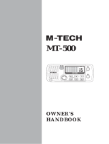
4.1.2 BATTERY CHARGING
If the radio has never been used, or its charge is depleted, it may be charged
by connecting the CD-36 Charger Cradle with the NC-90 battery charger, as
shown in the illustration.
When the battery pack is inserted correctly, the LED indicator on the CD-36
Charger Cradle will glow red. When charging
is completed, the LED indicator will change
to green.
Note: The radio may be kept in the charging
cradle when the radio is turned off. It is not
recommended to use turn the radio while it is
in the charger.
If 12V DC power is available, the supplied E-
DC-19A DC Cable with 12 V Cigarette Lighter
Plug or the optional E-DC-6 DC Cable may
be used for charging the battery. The NC-90,
E-DC-19A and E-DC-6 will charge a com-
pletely discharged FNB-V98LI battery pack
in about 8 hours.
4.1.3 BATTERY INSTALLATION/REMOVAL
1. Turn the transceiver off.
2. To install, insert the battery pack into the battery compartment on the back
of the transceiver, then close the Battery Pack Latch until it locks in place
with a “click.”
3. To remove, open the Battery Pack Latch on the bottom of the transceiver,
then slide the battery downward and out from the transceiver.
Close the Battery Pack Latch
Install the Battery Pack
NC-90
E-DC-6
E-DC-19A

HX600SPage 12
4.1.4 USING THE CD-36 CHARGER CRADLE
1. Turn the transceiver off.
2. Insert the DC plug from the NC-90 into the DC jack on the CD-36 side
panel, then plug the NC-90 into the AC line outlet.
3. Insert the HX600S (with the battery pack) into the CD-36; the antenna should
be at the left side when viewing the charger from the front.
4. If the HX600S is inserted correctly, the Red indicator on the CD-36 will
glow. A fully-discharged pack will be charged completely in approximately 8
hours.
Important Note:
Do not leave the charger connected to the transceiver for continuous
periods in excess of 24 hours. Long term overcharging can degrade the
Lithium-Ion battery pack and significantly shorten its useful life.
5. When charging is completed, disconnect the pack from the CD-36, and
unplug the NC-90 from the AC line outlet.
4.1.5 MOUNTING THE CD-36 ON THE VESSEL
The CD-36 is designed to be surface
on a vessel which can be connected to
the charger and a GPS that supplies NMEA data for DSC Distress transmis-
sions.
If mounting on a vessel, the CD-36 must be mounted in a location on the ves-
sel that is directly shielded from rain or splashes of water. After the location is
found, mount the CD-36 using the supplied mounting screws.
CD-36 Desktop Mount

HX600S Page 13
4.2 CONNECTING A GPS TO THE CD-36
The CD-36 is supplied with a cable that is designed to be connected to any
GPS that has an NMEA Output with the GLL, GGA, GNS, or RMC sen-
tences. Check with the owner’s manual of the GPS to confirm this informa-
tion. The NMEA input cable on the CD-36 contains two wires, uses are shown
below.
Blue – NMEA Input (Connects to NMEA Out of GPS)
Green – NMEA Negative (Connects to NMEA Negative or battery Ground of
GPS)
If you have further inquires, please feel free to contact us at:
Phone: (800) 767-2450
Fax: (888) 679-8046
Web site: standardhorizon.com
Email:
marinetech@vxstdusa.com
To connect the GPS receiver, connect the wires between the CD-36 and the
GPS. Insure that the wires are properly shielded from water. See the figure
at the right for example of connection to STANDARD HORIZON GPS CHART
PLOTTER.
Green
Blue
Green
Brown
16/9
WX
H/L
SUBMERSIBLE

HX600SPage 14
5. CONTROLS AND SWITCHES
NOTE
This section defines each control of the transceiver. For detailed operating
instructions, refer to section 6 “BASIC OPERATION.” Refer to illustra-
tions for the location of the following controls, switches, and connections.

HX600S Page 15
VOLUME CONTROL
Turn this control clockwise to increase the volume.
MIC/SP JACK
The jack accepts the optional CMP460 Speaker/Microphone, MH-57A4B
Mini Speaker/Microphone, VC-24 VOX Headset or VC-27 Earpiece/Mi-
crophone. When this jack is used, the internal speaker is disabled.
ANTENNA CONNECTOR
The supplied CAT460 flexible antenna is attached here.
PUSH-TO-TALK
(
PTT
)
SWITCH
When pushed activates the transmitter.
SQUELCH
(
SQL
)
SWITCH
Sets the point at which random noise on the channel will not activate the
audio circuits but a received signal does. This point is called the Squelch
threshold. Further adjustment of the squelch control will degrade the re-
ception of wanted transmissions. To quickly open the squelch and moni-
tor a channel before transmitting, press and hold this key for 3 seconds.
POWER SWITCH
Press and hold in this switch for 2 seconds to toggle the transceiver’s
power “on” and “off.”
[S(UP)] KEY
Press to select a desired channel. Each press increases the channel
number. When held down, the channels increase continuously.
[T(DOWN)] KEY
Press to select a desired channel. Each press decreases the channel
number. When held down, the channels decrease continuously.
[BAND] KEY
Press to select the VHF Marine, AM Broadcast, FM Broadcast, and AIR
(aircraft) bands.
MICROPHONE
The internal microphone is located here.
NMEA TERMINAL
Connect to GPS receiver that outputs NMEA sentences GLL, GGA, GNS,
and RMC via the CD-36 Charger Cradle. Keep these terminals clean.

HX600SPage 16
[16/9] KEY
Immediately recalls channel 16 from any marine channel or band loca-
tion. Holding down this key recalls channel 9.
[WX] KEY
Immediately recalls the last-used NOAA Weather Channel from any chan-
nel location. Recalls the previously- selected working channel when the
[WX] key is pressed again.
Secondary use:
When the [16/9] key is held and the [WX] key is pressed, the radio will
change the marine channel between the USA, International, and Cana-
dian channels.
[H/L] KEY
On the Marine Band, changes the transmitter output power between High
(5 Watts), Medium (2.5 Watts), and Low (1 Watt). Does not operate on
“Low power only” and transmission-inhibit channels.
When operating on Canadian channel 13, or USA channels 13 or 67,
pressing this key momentarily toggles the power level from Low power to
medium or High power.
Secondary use:
Hold down this key to lock the keypad (except the PTT, SQL, and [H/L]
keys) so that they are not accidentally changed. The key lock symbol
“
” will appear on the LCD, to indicate that the functions are locked.
Hold down until the key lock symbol “
” disappears to unlock the radio.
[SCAN] KEY
Starts scanning and priority scanning of programmed channels. When
scanning, press and hold this key to turn on and off priority scan (P is
shown on the display during Priority scanning).
[PRESET] KEY
Immediately recalls one of up to 10 user preset memories for each band
(shown as 0-9 on the LCD). Pressing this key repeatedly scrolls through
the preset memory channels.

HX600S Page 17
[MEM] KEY
Press this key to memorize the selected channel for scanning. When
pressed a “MEM” icon will be shown on the LCD display indicating the
channel has been saved to scan memory. The scan memory is only used
with the Marine and WX channels.
To delete the channel from scan memory, select the channel and press
this key until “MEM” is removed from the display.
BUSY/TX INDICATOR
This indicator illuminates different colors de-
pending on the band that is selected. The
chart to the right shows the colors illuminated
when the signal is received. This indicator
glows red during transmit.
When the Emergency feature is activated, this indicator blinks the inter-
nationally-recognized Morse Code “S.O.S.” message.
[DISTRESS] KEY
When radio is programmed with a MMSI and this key is pressed once
and pressed and held again for 3 seconds the radio will transmit a DSC
Distress Call. To send the distress call, see section 7.10 “DIGITAL SE-
LECTIVE CALLING.”
BAND COLOR
MARINE Blue
AM Green
FM Marine Blue
AIR Yellow

HX600SPage 18
6. BASIC OPERATION
6.1 INITIAL SETUP
1. Install the battery pack on the transceiver (see section 4.1.3 “BATTERY
INSTALLATION/REMOVAL”).
2. Install the antenna onto the transceiver.
NOTE: Water resistance of the transceiver is assured only when the bat-
tery pack and antenna are attached to the transceiver and MIC/SP rub-
ber cap is installed in the MIC/SP jack.
6.2 RECEPTION
1. Press and hold in the POWER switch for two seconds to turn the trans-
ceiver on.
2. Press the SQL switch, then press the [T] key until
the SQL level is 00. This state is known as
“Squelch Off.”
3. Turn up the VOLUME CONTROL knob until the noise or audio from the
speaker is at a comfortable level.
4. Select the desired operating band among the VHF Marine band, FM band,
AM band, and AIR band by pressing the [BAND] key repetitively to switch
between the bands.
5. Press the [S] or [T] key to select a channel or frequency that has no
signal being received (no one is transmitting on the channel) and where
only noise is heard.
6. Press the SQL switch, then press the [S] key and stop immediately after
the noise disappears. This condition is known as the “Squelch Thresh-
old.” If the squelch is set to a higher level, weak signals may not be
received. No noise or no signal is heard until a signal is received that
exceeds the squelch threshold. Sometimes, a slight adjustment of the
squelch threshold is needed, as some channels have a higher noise level
than others.
NOTE: To quickly open the squelch and monitor a channel before trans-
mitting, press and hold this key for 3 seconds.
7. Press the [SCAN] key momentarily to channel the scanning. Refer to
section 7.2 for programming channels into scan memory.
8. Please refer to section 13 for VHF Marine channel assignments.
9. The LCD and keypad are illuminated for 5 seconds when any key is
pressed. The lamp automatically turns off in about 5 seconds.
10. To “lock” the channel so that it is not accidentally changed, hold down the
/