Page is loading ...

4G S2
Cell Phone Signal Booster
Manual
1
Manufactured and Warranted by
Amazboost Technology Inc.
www.amazboost.com
customer service number:
Office (435) 319-6858
Toll Free (877) 579-7878
Support@Signalbooster.zendesk.com
Operational Diagram
(How It Works)
Package Contents
Page 2
Installation Step By Step
Page 5 - 12
Trouble Shooting
Page 13 - 14
Technical Specification
Warranty Information
Page 15
Basic Signal Level Knowledge
Page 3
Preparation
Page 4
Safety Guidelines
Page 16

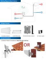
Working Diagram (How It Works)
Package Contents
1. The outdoor antenna catches the signal from the tower.
2. Sends outside signal to the booster through a coax cable.
3. The booster amplifies the signal then rebroadcasts the signal indoors to all mobile
devices within range.
4. The system also works in reverse; amplifying outgoing signal back to the tower.
The kit includes the following items:
1. Outdoor Antenna (with mounting kits);
2. Booster(with indoor antenna);
3. Power supply;
4. 60 ft of RG6 cable, for connecting the outdoor antenna and booster;
The coverage area and the strength of the boosted signal are directly
related to two key factors:
1. Signal strength received by the outdoor unit. So, setting up the outside
unit where the signal is the strongest will provide the best results.
2. Distance of separation between the outdoor unit and the indoor unit.
2
Outdoor Antenna
Booster & Indoor Antenna
Power supply
RG6 cable

Signal transmission loss and power level
Power level
at the outdoor antenna location
Coverage Area
(sq. ft.)
Strong (5 bars on the cellphone)
2,500
Medium (3~4 bars on the cellphone)
1,300
Weak (1~2 bars on the cellphone)
400
Coverage area ability
3
Note: FCC regulations limit the amplification of all cell phone boosters in order to
prevent damage to the telecommunications infrastructure. Therefore, the maximum
coverage area of a booster depends on the original power level of the signal captured by
the outdoor unit.
Notice: Not recommended when outdoor signal strength is less than -110dbm(3G/1x)
or -120dBm(4G/LTE). The resulting coverage area of the boosted signal will be
prohibitively small.

Find a cell tower nearby!
There are a variety of resources available online, here are some third party websites and
app recommended. Use these to locate your nearest cell tower, either by street address
of GPS coordinates.
For U.S. websites:
www.antennasearch.com/
www.cellmapper.net/
www.cellreception.com/towers
For Canada website:
www.cellmapper.net/
APP: Tower Locator (iPhone or Android)
Preparation
You Will Need (make sure the following things and tools are prepared and ready for your
installation. )
• 2~3 hours
• 2 people (a person to help with antenna calibration)
• Drill (if routing cable through wall)
• Recommended: Power Strip with surge protection
Find The dBm Reading On Your Phone
Having an accurate measurement of signal strength in decibels (dBm) is crucial when
installing your system. Decibels accurately measure the signal strength you are receiving.
Test both 3G and 4G signal for best results by turning the LTE off in the carrier settings of
your device.
iPhone: need to download third part APP;
Android: Settings > About Phone > Status or Network > Signal Strength or Network
Type and Strength (exact options/wording depends on phone model).
Note: Turn off your cell phone’s WiFi to ensure you are checking the cellular connection.
The dBm reading will be refreshed every 30-60 seconds. Want faster results? Once you
have a reading, turn on airplane mode. Wait 15 seconds. Turn off airplane mode. The
signal strength reading is refreshed.
4

Step2: Select the Location for the Inside Antenna
• Should have access to a
power outlet
• The indoor unit contains
an omni-directional
antenna. Choosing a
central location in your
home will help to
maximize your coverage
area.
Step1: Measure the Signal Strength Inside your Home
Test Installation
• Test your current signal strength in multiple locations throughout the home
• Record the current signal strength in the table provided for reference
Test Record
No
Location
Record(dBm)
1
2
3
4
5
5
We STRONGLY recommend doing a test installation before finalizing the installation.
Doing a test installation of your cell phone booster ensures that you will get the optimal
performance from your system.

Step3: Select the Location for the Outside Unit
1. This is the most critical step and will determine the overall performance of the
booster system.
2. Using the same method described in Step 1, walk around the outside of your home
and test the signal strength. Determine where you have the strongest signal (the
dBm reading is closest to zero).
3. Generally, the strongest signal will be located on the side of your home facing the
nearest cell tower. Keep in mind, the signal strength at ground level may be different
from the signal strength at or above the roofline due to obstructions (trees, other
buildings, etc.) that block the incoming signal. In most situations, the strongest signal
is found about 15 feet above the ground on the side of your home facing the nearest
cell tower.
Test Record
No
Location
Record(dBm)
1
2
3
4
5
6
Caution
• The height of the outside antenna should never exceed the highest point of your
home. This is a precaution against damage and safety concerns caused by lightning
strikes to the outside unit.
• In order to achieve the best performance, try to maximize the distance between the
inside and outside antenna.
• Ensure that the outside antenna is pointed away from where you plan to install the
inside antenna. Self-oscillation may occur if the outside antenna is pointed over the
location of the inside antenna.

Step 4: Temporarily Mount the Outside Antenna
Use one of the three options to mount the outside antenna on your roof on the side of
the house with the strongest signal
In order to achieve the best signal coverage effect,
there is a certain distance requirement between the
indoor and outdoor units. Make sure the inside and
outside units are facing away from each other.
Minimum Required Separation Distance Between
Indoor and Outdoor Antenna:
20 ft (6 meters) horizontal distance
13 ft (4 meters) vertical distance(As far as possible)
Make sure to meet the Minimum Separation
Requirements while at the same time mounting the
outside unit in the location with the strongest signal.
7
Caution

8
3. Connect the inside antenna to the
“INSIDE” port on the booster.
4. Plug in the power adaptor and
connect it to the nearest power outlet
(surge protector recommended).
2. Connect the “OUTSIDE” port on
booster and the outside antenna
together by using the coax cable.
Step5: Connect the System
1. Connect the outside antenna to the 30
feet RG6 cable, fix the connector(In order to
avoid internal damage of the antenna
connector due to gravity or pulling the cable)
Secure the cable near the antenna
to prevent cable damage caused
by wind shaking

Step6: Evaluate the Effects
Test Record
Decibel Gain vs. Power Amplification/Distance/Coverage area
Decibel Gain
Power Amplification
(times)
Distance Enhance
(times)
Coverage Enhance
(times)
6
4
2
4
10
8
3
9
20
100
8
64
30
1000
32
900
Note: Decibel Gain and Power Amplification may vary depending on the specifics of your
situation. Different building materials and other obstructions in your home will result in
different outcomes.
No
Location
Record(dBm)
1
2
3
4
5
9
• Now that the booster is up-and-running, re-test the signal strength inside your home
at the same locations from Step 1. If the number is higher (dBm reading is closer to
zero) than the original reading, your booster is working.
• If your signal is not stronger, check the LED lights on the booster and refer to the
“Quick Troubleshooting” section at the end of the manual.

Option B : Mounting on Side of Wall (Second Choice)
Caution
Step7: Finalizing Outdoor Antenna Installation
Outdoor Antenna Installation
Make sure that the outside unit is mounted at least 3 feet away from any windows.
Option A : Outside Roof Pole Mount (Best Choice) Use an existing pole to mount the
outdoor unit in the optimal signal location. Use the picture for reference.
10
Once you have tested the performance of the signal booster and made all necessary
adjustments, it’s time to finalize the installation.
In particular, cables for outdoor antenna locations
must be fixed. Otherwise, the internal wires of the
cable will be pulled off after the wind has been
shaken for a long time. The amplifier will not receive
the signal and the system will fail completely.
As shown in the figure, it is best to have the cable
around a single turn shape and then fix it.
Long-term rain or moisture erosion can damage
the electrical characteristics of outdoor antenna
connectors. Make sure connectors are well
screwed in and seal the connectors with glued tape.

Step9: Finalizing and Securing Cable Route
• Find the best route for the cable.
Follow the lines of your home to
hide the cable in eaves or
between the soffit and the
exterior wall.
• If needed, cable clips can be
purchased at most hardware
stores.
11
2. Mount the booster
• Choose a ventilated and dry place
• Keep away from heat
• Don't cover booster
Booster will about 30 degrees Fahrenheit
higher than the ambient temperature, which
is a normal phenomenon.
Step8: Finalizing Indoor Installation
1. Choose right position for the indoor antenna
• 20 cm away from any other metallic objects
• 50 cm away from any windows
• Whether the cable is properly
secured is very important for the
entire system. In most cases, the
customer found that the booster
did not work after working for a
period of time because the cable
was not installed securely.
• Carefully arrange the cable along
the outside of the building and
ensure that there are no folds or
kinks. Fix the cable at each corner

12
Make sure these excess coiled cables are more than 6 feet(2 meters) from the antenna
or booster can make your system work more stable.
If the coiled cable is too close to the antenna or booster, the system will be unstable.
Make sure these coiled cables are more than 6 feet(2 meters) from the antenna or
booster
Properly Handle Excess Cables
Caution
Secure the cable near
the antenna to prevent
cable damage caused by
wind shaking
Seal and Fix the Connector

Correct functioning:
• Power Light should be solid green
• The lights on the front panel indicate the condition of the booster. Every time the
booster is powered on, all of the lights will be green in color for several seconds then
off. This means the booster has passed the self check and is in good condition..
Quick Trouble shooting
Incorrect Functioning: (Please see the Troubleshooting Guide for further details)
• If any of the lights on the front panel are flashing in green then off/continue
flashing/solid green, it means that self oscillation is occurring. You must switch off the
booster and check the outside and inside antennas immediately. Make sure you have
followed the recommended installation process and check each step carefully. Refer to
Self Oscillation section for more details of minimum required separation distance,
antennas installation. If you can not fix the problem please contact the technical
support or the reseller.
Amazboost Technical Support: Support@Signalbooster.zendesk.com
Power Light Panel State Light
13
Trouble Shooting: No Signal Improvement
Step 1. Check power. Ensure the indoor
unit is plugged in and the LED Power Light
is green.

14
14
Trouble Shooting: No Signal Improvement
Step 2. Check cable connections. Ensure the indoor
and outdoor units are securely connected to the coax
cable.
Step 4. Double check the location of
outdoor and indoor units. Make sure that
the Minimum Separation Requirements
have been met. Make sure that the outside
antenna is not pointed towards the inside
antenna.
Minimum Required Separation Distance Between Indoor and Outdoor Unit:
Horizontal Distance = 20 feet (6 meters)
Vertical Distance = 13 feet (4 meters) (As far as possible)
Step 5. Check incoming signal level at outdoor
unit position. Usage of a booster is not
recommend when the outdoor signal is less
than -110dbm(3G/1x) or -120dBm(4G/LTE).
Step 3. If any of the lights on the front panel are
flashing in green then off/continue flashing/solid
green, it means that self oscillation is occurring. You
must switch off the booster and check the outside
and inside antennas immediately.
If you have any questions or concerns when installing or operating your cell phone booster, please
email us: Support@Signalbooster.zendesk.com
Or call our customer service:877-579-7878

Technical Specification
The Outdoor Unit and Indoor Unit are covered under a three-year product warranty for failures or
defects that result from craftsmanship and/or materials. Dated proof of purchase should be retained
for use in warranty cases. Contact the retailer/reseller directly with any warranty issues, or
alternatively contact the manufacturer in cases where the reseller is no longer available to handle
warranty claims. In cases where the reseller is unavailable, the product may be returned to the
manufacturer at the consumer’s expense, with a dated proof of purchase and a return authorization
letter which can be attained by contacting Amazboost.
This warranty does not apply to any signal booster components determined by Amazboost to have
been subjected to misuse, abuse, neglect, tampering, or mishandling that result in damages to the
physical or electronic properties of the product. Refurbished products that have been recertified to
conform to product specifications may be used for product replacements.
WARRANTY
DISCLAIMER: The information provided by Amazboost is believed to be complete and accurate, to the
best of our knowledge. However, no responsibility is assumed by Amazboost for any business or
personal losses arising from the use of the information herein contained, or for any infringements of
patents or other rights of third parties that may result from its use.
15
Frequency
(MHz)
LTE
(band 12)
LTE
(band 13)
Cellular
( band5)
PCS
(band 25/2)
AWS
(band 4)
Uplink
698-716
776-787
824-849
1850-1915
1710-1755
Downlink
728-746
746-757
869-894
1930-1995
2110-2155
Gain
Uplink
55±2
55±2
55±2
60±2
60±2
Downlink
60±2
60±2
60±2
65±2
65±2
Output power
26±2dBm(Uplink)/0±2dBm(Downlink)
Noise figure
<5dB
In-band Flatness
<8dB
Weight
0.7Kg
EIRP
1W
Impedance
50 ohm
Operating temperature
-5°~60°
Current
≦1.5A(6V DC)
Dimension(mm)
155*125*25
If you have any questions or concerns when installing or operating your cell phone booster, please
email us: Support@Signalbooster.zendesk.com
Or call our customer service:877-579-7878

To uphold network protection standards and ensure compliance, all active cellular devices must maintain a
separation distance of at least six feet between the inside unit antenna and outside unit antenna and at
least four feet of separation distance from the inside unit. Use only the power supply provided in this
package. Use of a non-Amazboost product or accessory may result in damage to the equipment or
components of the equipment. The inside unit is designed for use in an indoor, temperature-controlled
environment (less than 100 degrees Fahrenheit). It is not intended for use in attics or similar locations
where temperatures may be in excess of that range.
Safety Guidelines
RF Safety Warning: Any antenna used with this device must be located at least 8 inches from all persons.
This device complies with Part 15 of FCC rules. Operation is subject to two conditions: (1) This device may
not cause harmful interference, and (2) this device must accept any interference received, including
interference that may cause undesired operation. Changes or modifications not expressly approved by
Amazboost could void the authority to operate this equipment.
FOR MORE INFORMATION ON REGISTERING YOUR SIGNAL BOOSTER WITH YOUR WIRELESS PROVIDER,
PLEASE SEE BELOW:
Sprint: http://www.sprint.com/legal/fcc_boosters.html
T-Mobile/MetroPCS: https://support.t-mobile.com/docs/DOC-9827
Verizon Wireless: http://www.verizonwireless.com/wcms/consumer/register-signal-booster.html
AT&T: https://securec45.securewebsession.com/attsignalbooster.com/
U.S. Cellular: http://www.uscellular.com/uscellular/support/fcc-booster-registration.jsp
16
If you have any questions or concerns when installing or operating your cell phone booster, please
email us at
Support@Signalbooster.zendesk.com
Or call our customer service number
Office (435) 319-6858
Toll Free (877) 579-7878
/