- 4 -
Table of Contents
Box Contents ...................................................................................................................6
Optional Items .................................................................................................................6
GA-P55-UD4P/GA-P55-UD4 Motherboard Layout ..........................................................7
Block Diagram .................................................................................................................8
Chapter 1 Hardware Installation .....................................................................................9
1-1 Installation Precautions .................................................................................... 9
1-2 ProductSpecications .................................................................................... 10
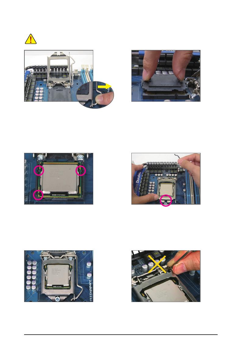
1-3 Installing the CPU and CPU Cooler ............................................................... 13
1-3-1 Installing the CPU ...................................................................................................13
1-3-2 Installing the CPU Cooler .......................................................................................15
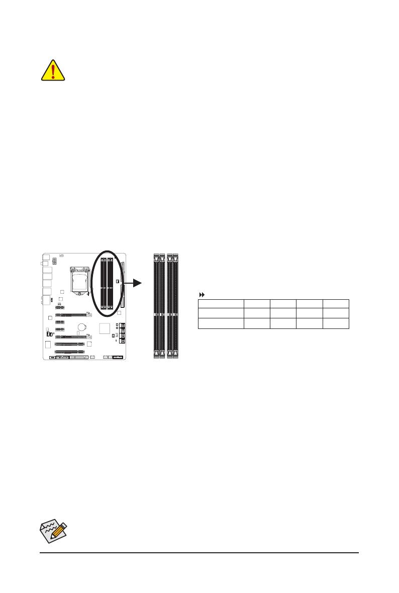
1-4 Installing the Memory ..................................................................................... 16
1-4-1 DualChannelMemoryConguration .....................................................................16
1-4-2 Installing a Memory ...............................................................................................17
1-5 Installing an Expansion Card ......................................................................... 18
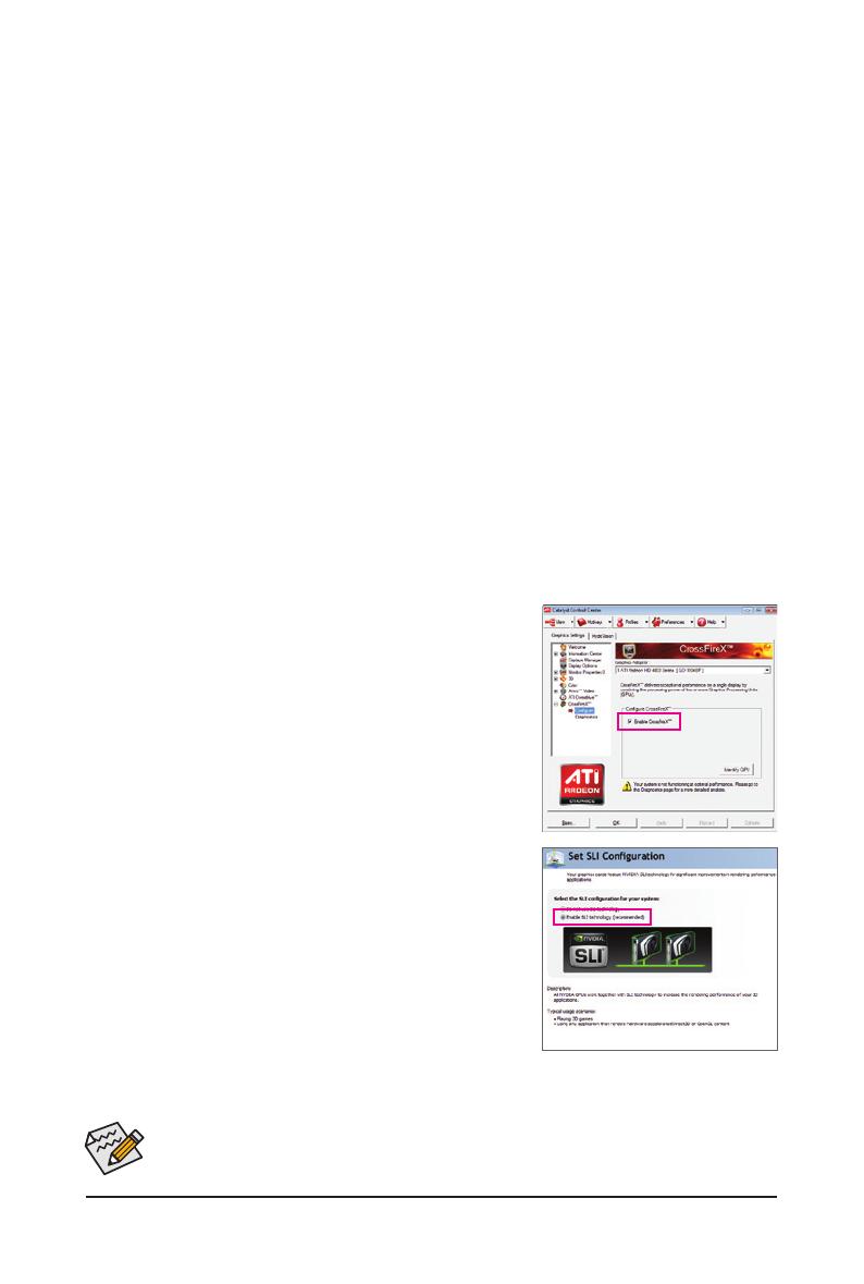
1-6 Setup of ATI CrossFireX
™
/NVIDIASLIConguration ..................................... 19
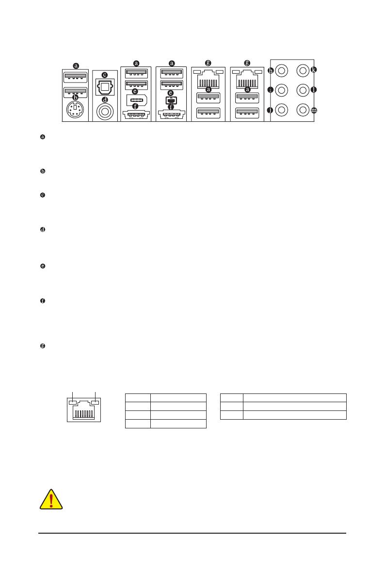
1-7 Back Panel Connectors .................................................................................. 20
1-8 Internal Connectors ........................................................................................ 22
Chapter 2 BIOS Setup ..................................................................................................35
2-1 Startup Screen ............................................................................................... 36
2-2 The Main Menu .............................................................................................. 37
2-3 MB Intelligent Tweaker(M.I.T.) ........................................................................ 39
2-4 Standard CMOS Features .............................................................................. 49
2-5 Advanced BIOS Features .............................................................................. 51
2-6 Integrated Peripherals .................................................................................... 53
2-7 Power Management Setup ............................................................................. 57
2-8 PC Health Status ............................................................................................ 59
2-9 Load Fail-Safe Defaults .................................................................................. 61
2-10 Load Optimized Defaults ................................................................................ 61
2-11 Set Supervisor/User Password ...................................................................... 62
2-12 Save & Exit Setup .......................................................................................... 63
2-13 Exit Without Saving ........................................................................................ 63
2-14 SecurityChipConguration
j
.................................................................. 64
Chapter 3 Drivers Installation ........................................................................................65
3-1 Installing Chipset Drivers ............................................................................... 65