
No.99MBA043A
SERIES No.302
PJ-A3000 Series
Measuring Projector
User’s Manual
Read this User's Manual thoroughly
before operating the instrument. After reading,
retain it close at hand for future reference.

Conventions Used in this User's Manual
This section describes the symbols (safety warning symbols) used in this manual.
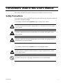
Safety Precautions
This manual uses various symbols to help you use this unit correctly, and prevent danger to
personnel or equipment damage.
• The following symbols indicate general dangers, warnings and cautions.
DANGER
Indicates an imminently hazardous situation which, if not avoided, will result in serious
injury or death.
WARNING
Indicates a potentially hazardous situation which, if not avoided, will result in serious
injury or death.
CAUTION
Indicates a potentially hazardous situation which, if not avoided, may result in minor or
moderate injury or property damege.
• The following symbols indicate specific warnings or prohibited actions.
Alerts the user to a specific hazardous situation. The given example means “Caution,
risk of electric shock”.
Prohibits a specific action. The given example means “Do not disassemble”.
No.99MBA043A i

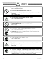
Do not modify this instrument.
Risk of fire or electric shock.
Do not bend, twist, pull, or modify the power cord.
Risk of fire or electric shock.
Do not remove the front panel, rear panel, side panel or covers of this
instrument.
Risk of electric shock.
Only operate this instrument at the specified voltage.
Risk of fire or electric shock.
Do not set up this instrument on an unstable bench.
The instrument may fall.
Risk of injury.
Do not place a vessel containing liquid near the instrument.
Risk of fire or electric shock.
Unplug the power cord and contact Mitutoyo if liquid has entered the
instrument.
Risk of fire or electric shock.
Unplug the power cord if replacing a fuse.
Risk of electric shock.
The AC outlet incorporated with the instrument is only available for
Mitutoyo accessories.
Do not plug in other equipment.
Risk of fire.
Should this system be used under abnormal conditions such as heat
radiation, smoking, and nasty smell generation, there is a risk of fire or
electric shock.
Immediately turn off the power switch, then unplug the power plug from
the outlet.
Contact your dealer or the nearest Mitutoyo service network.
No.99MBA043A
ii

Unplug the power cord if performing maintenance.
Do not pull the cable to unplug the power cord.
Hold the plug and pull to prevent cord breakage.
Risk of fire or electric shock.
Do not connect/disconnect or touch the plug with wet hands.
Risk of electric shock.
Keep the power cord away from heaters.
Risk of fire or electric shock with melted cable insulation.
Only use the specified fuse.
Risk of fire or electric shock.
Do not block the ventilation outlets.
Risk of fire due to internal heat build up.
For quick power shutoff install this system at a site where the system
power plug can be easily identified and quickly accessed to be
unplugged.
No.99MBA043A iii

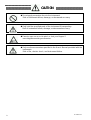
Do not apply excessive force to the instrument.
Risk of instrument failure, damage, or decreased accuracy.
Only hold the specified parts of the instrument if transporting.
Risk of instrument failure, damage, or decreased accuracy.
Exercise care so as not to pinch or hurt your fingers if
mounting/dismounting accessories.
Only use the accessories specified in the User’s Manual provided with the
instrument.
Risk of fire, electric shock, and instrument failure.
No.99MBA043A
iv

CONVENTIONS USED IN USER'S MANUALCONVENTIONS USED IN USER'S MANUAL
On Various Types of NotesOn Various Types of Notes
The Following types of notes are provided to help the operator obtain measurement data
through correct instrument operation.
The Following types of notes are provided to help the operator obtain measurement data
through correct instrument operation.
An important note is a type of note that provides information essential to the
completion of a task. You cannot disregard this note to complete the task.
An important note is a type of note that provides information essential to the
completion of a task. You cannot disregard this note to complete the task.
An important note is a type of precaution, which if neglected could result in a
loss of date, decreased accuracy or instrument malfunction/failure.
An important note is a type of precaution, which if neglected could result in a
loss of date, decreased accuracy or instrument malfunction/failure.
IMPORTANT IMPORTANT
NOTE NOTE A note emphasizes or supplements important points of the main text. A note
supplies information that may only apply in special cases(e.g.. Memory
limitations, equipment configurations, or details that apply to specific versions
f)
described in the text to their specific needs.
It also provides reference information associated w
described in the text to their specific needs.
It also provides reference information associated w
A note emphasizes or supplements important points of the main text. A note
supplies information that may only apply in special cases(e.g.. Memory
limitations, equipment configurations, or details that apply to specific versions
f)
discussed
TIP A tip is a type of note that helps the user apply the techniques and procedures
ith the topic being
No.99MBA043A v
TIP A tip is a type of note that helps the user apply the techniques and procedures
ith the topic being
Mitutoyo assumes no liability to any party for any loss or damage, dir
ect or indirect, caused by use of this instrument not conforming to thi
s manual.
Information in this document is subject to change without notice.
© Copyright Mitutoyo Corporation. All rights reserved.
No.99MBA043A v

Handling Precautions
1. Confirm the input voltage before turning the power switch on
For the input voltage of this microscope, there are two systems of 100V-system (100
to 120V) and 220V-system (220 to 240V). Connect the power plug with the plug
socket after confirming that the rated voltage of the microscope corresponds with the
voltage of plug socket.
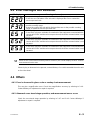
2. Turn the power switch ON or OFF along the order
The counter may display error messages (E51, E52, E53) by the order which turns
the power supply of the microscope main unit and the peripheral equipment such as
personal computer on or off in the connection with some peripheral equipment, when
the peripheral equipment is being connected with the counter unit at RS232C.
Be sure to perform at the following order, when turning the power switch ON or OFF.
• For ON ∙∙∙∙∙ Peripheral equipment Projector main unit
• For OFF ∙∙∙∙ Projector main unit Peripheral equipment
3. Only use the specified power cord and fuse
Use only the supplied power cord. Replacement fuses must be of the specified type,
voltage and current.
4. Do not disassemble
Disassembly of any unit or removal of panels may present a hazard to personal or
result in a unit failure. Never attempt to disassemble, unless absolutely essential, e.g.
for the replacement of a fuse, etc..
This instrument consists of precision components, and its performance cannot be
guaranteed, even within the warranty period, if it is disassembled by the user.
All equipment failures that occur after user disassembly will be repaired on a fee-for-
service basis.
Guarantee
This system has been manufactured under Mitutoyo's rigorous quality control system.
In the event that it proves defective in workmanship or materials within one year of the
date of purchase under normal usage, Mitutoyo will repair the instrument free of charge.
Contact your dealer or nearest Mitutoyo Service Center.
This guarantee does not apply to the following cases:
Equipment failure or damage due to incorrect usage or unauthorized modification or
repair.
Equipment failure or damage resulting from moving, transporting, or dropping the
instrument.
Equipment failure or damage due to fires, salt damage, gas damage, abnormal
voltages, or natural disasters.
No.99MBA043A
vi

CONTENTS
Conventions Used in this User's Manual .................................................................1
Safety Precautions .....................................................................................................1
On Various Types of Notes........................................................................................5
Handling precautions.................................................................................................6
Guarantee....................................................................................................................6
1. Overview ............................................................................................... 1-1
1.1 Outline.................................................................................................................1-1
1.1.1 Name of Each Part ............................................................................................................. 1-1
1.1.2 Control panel..................................................................................................................... 1-2
1.1.3 Angle counter and X, Y counter....................................................................................... 1-3
1.1.4 Power panel....................................................................................................................... 1-4
2. Installation and Setup .......................................................................... 2-1
2.1 Installation ...........................................................................................................2-1
2.1.1 Environmental Conditions................................................................................................ 2-1
2.1.2 Transportation and installation......................................................................................... 2-2
2.1.3 Setting up the main unit.................................................................................................... 2-3
2.1.4 Removing the carrying handles....................................................................................... 2-3
2.2 Assembly.............................................................................................................2-4
2.2.1 Installing the cross-travel stage and Digimatic Head (for PJ-A3005D-50)...................2-4
2.2.2 Installing the cross-travel stage and connecting the Linear Scale cables (PJ-A3010F-200).2-7
2.2.3 Connecting the Optoeye A2 Image Edge Sensor for PJ-3010F-200 .....................2-9
2.2.4 Mounting the projection lens..........................................................................................2-10
2.2.5 Setting the power voltage............................................................................................2-10
2.2.6 Connecting the power cord .........................................................................................2-11
2.3 Initial Checks (Functional Check)......................................................................2-12
2.3.1 Electrical component connectors................................................................................... 2-12
2.3.2 Main switch (ON-OFF).................................................................................................... 2-12
2.3.3 Switches for Contour illumination and reflected illumination....................................... 2-12
2.3.4 Focusing wheel ............................................................................................................... 2-12
2.3.5 Cross-travel stage........................................................................................................... 2-13
2.3.6 Projection screen ............................................................................................................ 2-13
2.3.7 Others............................................................................................................................... 2-13
2.4 Initial Checks (Performance Check)..................................................................2-14
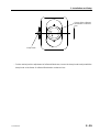
2.4.1 Checking the position of the contour illumination bulb filament.................................. 2-14
2.4.2 Checking the position of the surface illumination bulb filament.................................. 2-14
2.4.3 Projection with contour illumination............................................................................... 2-16
2.4.4 Projection with reflected illumination............................................................................. 2-17
2.4.5 Color fitter........................................................................................................................ 2-18
2.4.6 Checking the magnification accuracy............................................................................ 2-19
2.4.7 Checking the cross-travel stage travel direction........................................................... 2-21
2.4.8 Checking the cross-travel stage feed error................................................................... 2-23
2.4.9 Checking the resolution (in contour illumination mode)............................................... 2-23
No.99MBA043A vii

2.5 Adjustment........................................................................................................ 2-24
2.5.1 Adjusting the magnification............................................................................................2-24
2.5.2 Aligning the cross-travel stage travel direction to the cross-hair lines........................ 2-24
2.5.3 Centering the protractor screen..................................................................................... 2-24
3. Operation...............................................................................................3-1
3.1 Projection Lens Selection................................................................................... 3-1
3.1.1 Selecting the projection lens......................................................................................3-1
3.1.2 Replacing the projection lens....................................................................................3-2
3.2 Mounting the Workpiece..................................................................................... 3-2
3.3 Focusing and Positioning the Workpiece............................................................ 3-4
3.3.1 Focusing............................................................................................................................. 3-4
3.3.2 Positioning the workpiece................................................................................................. 3-5
3.4 Measurement and Inspection ............................................................................. 3-6
3.4.1 Rectangular coordinate measurement (with the X, Y counter) ..................................... 3-6
3.4.2 About parameters............................................................................................................ 3-9
3.4.3 Dimensional measurement using a scale..................................................................... 3-15
3.4.4 Comparison with an overlay chart ................................................................................. 3-15
3.4.5 Angle measurement (Using the Angle counter) ........................................................... 3-16
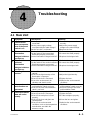
4. Troubleshooting....................................................................................4-1
4.1 Main Unit............................................................................................................. 4-1
4.2 Counter Unit........................................................................................................ 4-2
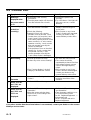
4.3 Error Messages and Remedies .......................................................................... 4-3
4.4 Others................................................................................................................. 4-3
4.4.1 Error is observed in glass scale or overlay chart measurement................................... 4-3
4.4.2 Abnormal cross-travel stage operation, and measurement errors occur.....................4-3
4.4.3 Abnormal protractor screen operation............................................................................. 4-4
4.4.4 Partial obscured image..................................................................................................... 4-4
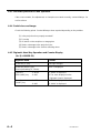
4.4.5 Digimatic Head Key Operation and Counter Display (for PJ-A3005D-50)................... 4-4
5. Maintenance ..........................................................................................5-1
5.1 Maintenance of Optical Components.................................................................. 5-1
5.1.1 Projection lens................................................................................................................... 5-1
5.1.2 Half-reflecting mirror for surface illuminator.................................................................... 5-1
5.1.3 Mirror(surface reflecting mirror) .......................................................................................5-1
5.1.4 Screen glass...................................................................................................................... 5-1
5.2 Maintenance of Mechanical Components........................................................... 5-2
5.2.1 Projector main unit............................................................................................................ 5-2
5.2.2 Cross-travel stage............................................................................................................. 5-2
5.3 Replacing Disposable Parts................................................................................ 5-3
5.3.1 Bulbs for contour and surface illuminators......................................................................5-3
5.3.2 Fuse ..................................................................................................................................5-5
5.3.3 Stage glass........................................................................................................................ 5-6
5.4 Periodic Inspection ............................................................................................. 5-6
5.5 List of Consumable............................................................................................. 5-7
No.99MBA043A
viii

6. Specifications ....................................................................................... 6-1
6.1 General................................................................................................................6-1
6.1.1 Common Specifications.................................................................................................... 6-1
6.1.2 Individual specifications.................................................................................................... 6-3
6.1.3 Date output RS232C .................................................................................................. 6-4
6.1.4 Connector specifications.................................................................................................. 6-4
6.1.5 Data output operation....................................................................................................... 6-6
6.1.6 Connecting Micropak........................................................................................................ 6-9
6.1.7 Connecting QM-Data 200............................................................................................... 6-10
6.1.8 Data output (SPC)........................................................................................................... 6-10
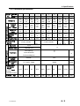
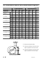
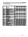
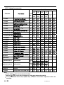
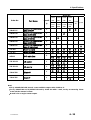
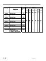
6.2 Performance Table for the PJ-A3000 Series Projectors...........................................6-14
6.3 Optical Path.......................................................................................................6-15
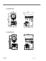
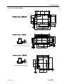
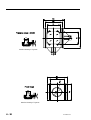
6.4 External dimensions..........................................................................................6-16
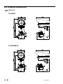
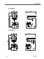
6.4.1 Main Unit.......................................................................................................................... 6-16
6.4.2 Cross-travel stage........................................................................................................... 6-19
6.5 Accessories.......................................................................................................6-21
6.5.1 Standard accessories..................................................................................................... 6-21
6.5.2 Optional accessories ...................................................................................................... 6-22
SERVICE NETWORK
No.99MBA043A ix

No.99MBA043A
x
MEMO

Overview
This chapter describes the system outline, and the name and
function of each part on the PJ-A3000 series Measuring Projector.
1
1.1 Outline
The Mitutoyo PJ-A3000 series Measuring Projector is a multi-purpose measuring microscope for
factory inspection use. It can perform precision measurement of workpiece dimensions, contours
and surface features.
The PJ-A3000 series can be used in a wide range of applications in combination with a variety of
accessories. It is possible to improve the system according to a specific purpose.
The MF-A series has the following features.
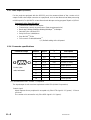
• The cross-travel stage with a maximum stroke of 200 X 100mm is available as an option.
• For the counter display, the readout is easy since the characters are large.
• For the counter display unit, following three types are prepared ; angle and X,Y-axis/ only
angle/ no display
• For both the contour and the reflective light source unit, the halogen bulb of 500 hours life with
24V and 150W is used.
• By the slide switching mechanism, the quick bulb exchange is possible.
• The operability is improved still more, because each switches are placed at the front and right
side of main unit.
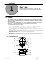
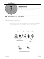
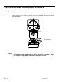
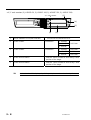
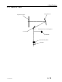
1.1.1 Name of Each Part
[13]
[11]
[12]
[9]
[8]
[14]
[6]
[4]
[3]
[1]
[2]
[5]
[7]
[10]
No.99MBA043A 1 - 1

[1] Projector head
[2] Projection screen
[3] Screen rotating knob
[4] Screen clamp knob
[5] Angle counter
[6] XY counter
[7] Projection lens
[8] Reflected illuminator, Condenser lens for reflected illuminator
[9] Cross-travel stage
[10] Control panel
[11] Contour illuminator (interior)
[12] Focusing wheel
[13] Power panel
[14] XY counter output connector
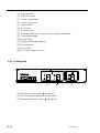
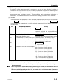
1.1.2 Control panel
[3] [2] [1]
[1] Main switch (Power switch) (|:ON / }:OFF)
[2] Contour illumination brightness selector switch
[3] Reflected illumination switch (|:ON / }:OFF)
1 - 2 No.99MBA043A

1. Overview
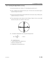
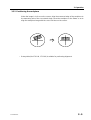
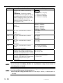
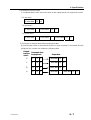
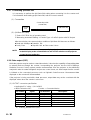
1.1.3 Angle counter and X, Y counter
(1) Angle counter (2) X, Y-axis counter
[2] [7] [8] [6] [10]
[9] [3] [5] [4] [1]
(1) Angle counter
[1] Angle display unit
[2] Zero-set key
[3] ABS/INC mode indicator
[4] Angle unit selector / offset switch
[5] ABS/INC mode selector switch
(2) X, Y-axis counter
[6] mm/E indicator or inch/mm indicator
[7] X-axis counter
[8] Y-axis counter
[9] X-axis zero-set switch
[10] Y-axis zero-set switch
No.99MBA043A 1 - 3

1 - 4 No.99MBA043A
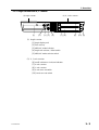
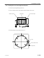
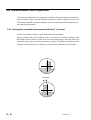
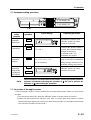
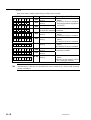
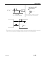
1.1.4 Power panel (Right lateral front part of main unit)
[5]
[2]
[1]
[3]
[4]
[1] Plug socket
[2] Fuse holder
[3] Voltage selector
[4] GND terminal
[5] Power switch

Installation and Setup
This chapter describes the installation environments and connection
method of the PJ-A3000 series Measuring Projector.
2.1 Installation
2
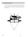
2.1.1 Environmental Conditions
2.1.1.1 Temperature
The PJ-A3000 series Measuring Projector has been assembled and adjusted at 20°C in a
temperature controlled room. To ensure the rated measuring accuracy, the temperature at
the installation site must be maintained as close to 20°C as possible, with minimal
fluctuation. (For reference, the conditions specified by JMAS5011 are: 20°C ± 1°C with a
temperature gradient of less than 2°C per 8 hours.) In poor temperature conditions, the
accuracy performance may not be satisfied. It is illegal to make any machine adjustments
affecting the accuracy at ambient temperatures other than 20°C. After such adjustment,
accuracy is no longer guaranteed at 20°C.
2.1.1.2 Humidity
Humidity will not affect the measuring accuracy directly. However, high humidity may
corrode machined surfaces and may adversely affect electronic parts. The environmental
humidity should be maintained within a range of 55% to 65%RH.
2.1.1.3 Dust and dirt
The PJ-A3000 series Measuring Projector consists of high-precision parts, including guide
faces, linear scale units, and optical unit, that must be kept free of dust and dirt. Use and
store the PJ-A3000 series Measuring Projector in a place where it will not be subjected to
dust and dirt.
2.1.1.4 Grounding
Connect the ground terminal with the ground terminal of grounding resistance 100 Ω or less
so that the measuring microscope may normally operate.
On the Reinstallation yyyyy The projector main unit reinstallation performed on the client's
own may deteriorate the required accuracy due to vibrations and shocks during
transportation. Therefore, it is recommended that the main unit be reinstalled by Mitutoyo. If
the system is desired to be reinstalled, be sure to contact the Mitutoyo sales office.
TIP
No.99MBA043A 2 - 1

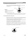
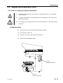
2.1.2 Transportation and installation
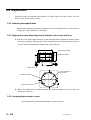
Be sure to use the supplied carrying handles when handling, shifting or installing the projector
and due to its heavy weight (for PJ-A3010F-200, about 120kg) four people are required to
carry it. The PJ-A3000 series has been fully adjusted at the plant, therefore take special care
when handling and setting up the projector so that no part of the projector is subjected to
impact or vibration.
Carrying handles
2 - 2 No.99MBA043A

2. Installation and Setup
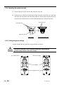
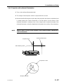
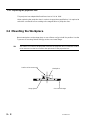
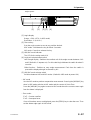
2.1.3 Setting up the main unit
The projector must be set up on the optional stand or a rigid, stable mount. Use the leveling
bolts on the projector base to compensate for any inclination.
Carrying handles Leveling bolts
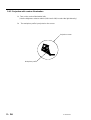
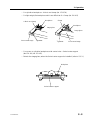
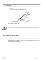
2.1.4 Removing the carrying handles
After setup, remove the carrying handles and cover the screw holes with the supplied hole
caps.
Hole caps
Carrying handles
No.99MBA043A 2 - 3

2.2 Assembly
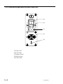
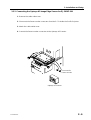
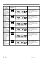
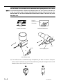
2.2.1 Installing the cross-travel stage and Digimatic Head (for PJ-A3005D-50)
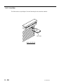
1. Turn the focusing wheel clockwise to lower the cross-travel stage mount down to the
end of its displacement.
Focusing wheel
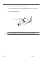
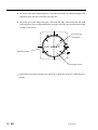
2. Gently place the cross-travel stage on the mount. Slide the moving sections to the
left and right to check the screw hole positions, then use the four hex-socket head
screws (supplied in the standard accessory box) to temporarily fix the cross-travel
stage in place.
Cross-travel stage
Hex-socket head screw
The cross-travel stage should be secured when the adjustment of its travel direction is complete.
(Refer to 2.5.2 Aligning the cross-travel stage travel direction to the cross-hair lines.)
TIP
2 - 4 No.99MBA043A

2. Installation and Setup
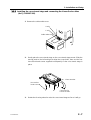
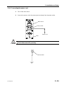
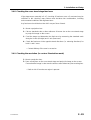
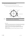
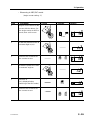
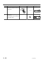
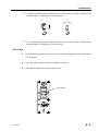
3. Installing the Digimatic Head
y Loosen the clamp screw and hex-socket head screw on the bracket.
y Slowly insert the stem of the Digimatic Head into the bracket as far as it can go, then
secure it in place with the hex-socket head screw. Do not fasten the screw too tight,
otherwise the spindle of the Digimatic Head will not move smoothly.
Hex-socket head screw
Bracket
Clamp screw
Allen spanner
Digimatic Head
y When using a Digimatic Head or other types of heads that are not provided with a hole to clamp
the spindle, the clamp screw is not used to secure it, lightly fasten the screw.
TIP
y The Micrometer Head is provided with a hole for damping the spindle. Align this hole with the
clamp screw. If the display is not in a good viewing position, loosen the clamp screw on the
Micrometer Head sleeve, and adjust the display position.
No.99MBA043A 2 - 5
Page is loading ...
Page is loading ...
Page is loading ...
Page is loading ...
Page is loading ...
Page is loading ...
Page is loading ...
Page is loading ...
Page is loading ...
Page is loading ...
Page is loading ...
Page is loading ...
Page is loading ...
Page is loading ...
Page is loading ...
Page is loading ...
Page is loading ...
Page is loading ...
Page is loading ...
Page is loading ...
Page is loading ...
Page is loading ...
Page is loading ...
Page is loading ...
Page is loading ...
Page is loading ...
Page is loading ...
Page is loading ...
Page is loading ...
Page is loading ...
Page is loading ...
Page is loading ...
Page is loading ...
Page is loading ...
Page is loading ...
Page is loading ...
Page is loading ...
Page is loading ...
Page is loading ...
Page is loading ...
Page is loading ...
Page is loading ...
Page is loading ...
Page is loading ...
Page is loading ...
Page is loading ...
Page is loading ...
Page is loading ...
Page is loading ...
Page is loading ...
Page is loading ...
Page is loading ...
Page is loading ...
Page is loading ...
Page is loading ...
Page is loading ...
Page is loading ...
Page is loading ...
Page is loading ...
Page is loading ...
Page is loading ...
Page is loading ...
Page is loading ...
Page is loading ...
Page is loading ...
Page is loading ...
Page is loading ...
Page is loading ...
Page is loading ...
Page is loading ...
Page is loading ...
Page is loading ...
Page is loading ...
Page is loading ...
Page is loading ...
Page is loading ...
Page is loading ...
-
 1
1
-
 2
2
-
 3
3
-
 4
4
-
 5
5
-
 6
6
-
 7
7
-
 8
8
-
 9
9
-
 10
10
-
 11
11
-
 12
12
-
 13
13
-
 14
14
-
 15
15
-
 16
16
-
 17
17
-
 18
18
-
 19
19
-
 20
20
-
 21
21
-
 22
22
-
 23
23
-
 24
24
-
 25
25
-
 26
26
-
 27
27
-
 28
28
-
 29
29
-
 30
30
-
 31
31
-
 32
32
-
 33
33
-
 34
34
-
 35
35
-
 36
36
-
 37
37
-
 38
38
-
 39
39
-
 40
40
-
 41
41
-
 42
42
-
 43
43
-
 44
44
-
 45
45
-
 46
46
-
 47
47
-
 48
48
-
 49
49
-
 50
50
-
 51
51
-
 52
52
-
 53
53
-
 54
54
-
 55
55
-
 56
56
-
 57
57
-
 58
58
-
 59
59
-
 60
60
-
 61
61
-
 62
62
-
 63
63
-
 64
64
-
 65
65
-
 66
66
-
 67
67
-
 68
68
-
 69
69
-
 70
70
-
 71
71
-
 72
72
-
 73
73
-
 74
74
-
 75
75
-
 76
76
-
 77
77
-
 78
78
-
 79
79
-
 80
80
-
 81
81
-
 82
82
-
 83
83
-
 84
84
-
 85
85
-
 86
86
-
 87
87
-
 88
88
-
 89
89
-
 90
90
-
 91
91
-
 92
92
-
 93
93
-
 94
94
-
 95
95
-
 96
96
-
 97
97


Mitutoyo Measuring Projector User manual
- Type
- User manual
- This manual is also suitable for
Ask a question and I''ll find the answer in the document
Finding information in a document is now easier with AI
Related papers
Other documents
-
Sharper Image 208884 User guide
-
Ransburg MICROPAK A11789 User manual
-
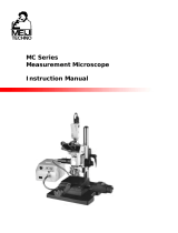 Meiji Techno MC series Owner's manual
-
ANZZI BA-LMDFX023AL User manual
-
 Magnescale LY71 Owner's manual
-
STECA TR 0502 U User manual
-
Niigata seiki DL-S3 User manual
-
Mitsubishi Electric AE-200A User manual
-
Nikon OPTIPHOT-POL Instructions Manual
-
 SPI TRONIC PRO 360 Digital Level Protractor Inclinometer Owner's manual


