Panasonic CS-C18MKP-7 User manual
- Category
- Split-system air conditioners
- Type
- User manual
This manual is also suitable for

© Panasonic HA Air-Conditioning (M) Sdn. Bhd. 2011.
Unauthorized copying and distribution is a violation of law.
Order No: PHAAM1106129C3
Indoor Unit Outdoor Unit
CS-C7MKP-7
CS-C9MKP-7
CS-C12MKP-7
CS-C18MKP-7
CS-C24MKP-7
CU-C7MKP-7
CU-C9MKP-7
CU-C12MKP-7
CU-C18MKP-7
CU-C24MKP-7
This service information is designed for experienced repair technicians only and is not designed for use by the general public.
It does not contain warnings or cautions to advise non-technical individuals of potential dangers in attempting to service a product.
Products powered by electricity should be serviced or repaired only by experienced professional technicians. Any attempt to service
or repair the products dealt with in this service information by anyone else could result in serious injury or death.
WARNING
Downloaded from www.Manualslib.com manuals search engine

2
TABLE OF CONTENTS
1. Safety Precautions .............................................3
2. Specification .......................................................5
3. Features.............................................................11
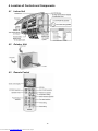
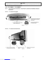
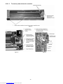
4. Location of Controls and Components..........12
4.1 Indoor Unit ..................................................12
4.2 Outdoor Unit ...............................................12
4.3 Remote Control ..........................................12
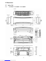
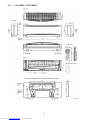
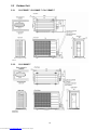
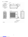
5. Dimensions .......................................................13
5.1 Indoor Unit ..................................................13
5.2 Outdoor Unit ...............................................15
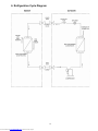
6. Refrigeration Cycle Diagram ...........................17
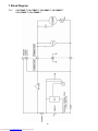
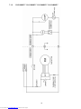
7. Block Diagram ..................................................18
8. Wiring Connection Diagram ............................20
8.1 CS-C7MKP-7 CU-C7MKP-7
CS-C9MKP-7 CU-C9MKP-7
CS-C12MKP-7 CU-C12MKP-7 ...................20
8.2 CS-C18MKP-7 CU-C18MKP-7..................21
8.3 CS-C24MKP-7 CU-C24MKP-7..................22
9. Electronic Circuit Diagram ..............................23
9.1 CS-C7MKP-7 CU-C7MKP-7
CS-C9MKP-7 CU-C9MKP-7
CS-C12MKP-7 CU-C12MKP-7 ...................23
9.2 CS-C18MKP-7 CU-C18MKP-7..................24
9.3 CS-C24MKP-7 CU-C24MKP-7..................25
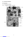
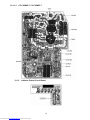
10. Printed Circuit Board .......................................26
10.1 Indoor Unit ..................................................26
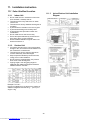
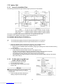
11. Installation Instruction.....................................30
11.1 Select the Best Location.............................30
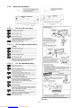
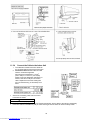
11.2 Indoor Unit ..................................................31
11.3 Outdoor Unit ...............................................35
12. Operation Control.............................................38
12.1 Cooling Operation.......................................38
12.2 Soft Dry Operation......................................40
12.3 Automatic Operation...................................42
12.4 Indoor Fan Speed Control ..........................43
12.5 Outdoor Fan Speed Control .......................45
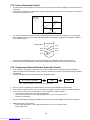
12.6 Vertical Airflow Direction Control................45
12.7 Horizontal Airflow Direction Control............47
12.8 Powerful Operation.....................................48
12.9 Quiet Operation ..........................................48
12.10 Timer Control..............................................49
12.11 Random Auto Restart Control ....................49
12.12 Remote Control Signal Receiving
Sound .........................................................49
12.13 Patrol Operation .........................................50
12.14 E-ion operation ...........................................54
12.15 AUTO COMFORT and ECO NAVI
Operation....................................................57
13. Protection Control............................................62
13.1 Restart Control (Time Delay Safety
Control).......................................................62
13.2 7 Minutes Time Save Control .................... 62
13.3 60 Seconds Forced Operation .................. 62
13.4 Starting Current Control ............................ 62
13.5 Freeze Prevention Control ........................ 63
13.6 Compressor Reverse Rotation Protection
Control ....................................................... 63
13.7 Dew Prevention Control ............................ 64
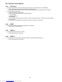
14. Servicing Mode ................................................ 65
14.1 Auto OFF/ON Button ................................. 65
14.2 Remote Control Button.............................. 66
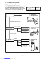
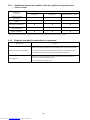
15. Troubleshooting Guide................................... 67
15.1 Refrigeration cycle system ........................ 67
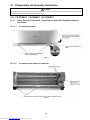
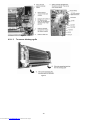
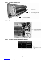
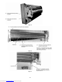
16. Disassembly and Assembly Instructions ..... 69
16.1 CS-C7MKP-7 CS-C9MKP-7
CS-C12MKP-7........................................... 69
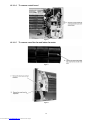
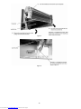
16.2 CS-C18MKP-7 CS-C24MKP-7................. 73
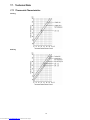
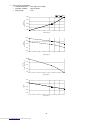
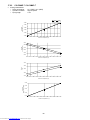
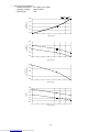
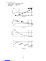
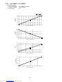
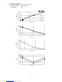
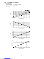
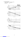
17. Technical Data ................................................. 77
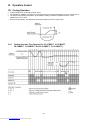
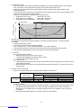
17.1 Thermostat Characteristics ....................... 77
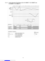
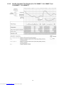
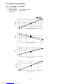
17.2 Operation Characteristics.......................... 78
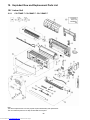
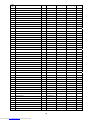
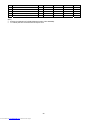
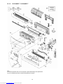
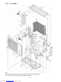
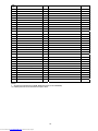
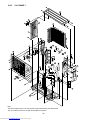
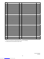
18. Exploded View and Replacement Parts
List .................................................................... 88
18.1 Indoor Unit ................................................. 88
18.2 Outdoor Unit .............................................. 94
Downloaded from www.Manualslib.com manuals search engine

3
CAUTION
WARNING
WARNING
1. Safety Precautions
Read the following “SAFETY PRECAUTIONS” carefully before perform any servicing.
Electrical work must be installed or serviced by a licensed electrician. Be sure to use the correct rating of the
power plug and main circuit for the model installed.
The caution items stated here must be followed because these important contents are related to safety. The
meaning of each indication used is as below. Incorrect installation or servicing due to ignoring of the instruction
will cause harm or damage, and the seriousness is classified by the following indications.
This indication shows the possibility of causing death or serious injury.
This indication shows the possibility of causing injury or damage to properties.
The items to be followed are classified by the symbols:
Carry out test running to confirm that no abnormality occurs after the servicing. Then, explain to user the
operation, care and maintenance as stated in instructions. Please remind the customer to keep the operating
instructions for future reference.
1. Do not modify the machine, part, material during repairing service.
2. If wiring unit is supplied as repairing part, do not repair or connect the wire even only partial wire break. Exchange the whole wiring unit.
3. Do not wrench the fasten terminal. Pull it out or insert it straightly.
4. Engage dealer or specialist for installation and servicing. If installation of servicing done by the user is defective, it will cause water leakage,
electrical shock or fire.
5. Install according to this installation instructions strictly. If installation is defective, it will cause water leakage, electric shock or fire.
6. Use the attached accessories parts and specified parts for installation and servicing. Otherwise, it will cause the set to fall, water leakage, fire
or electrical shock.
7. Install at a strong and firm location which is able to withstand the set’s weight. If the strength is not enough or installation is not properly done,
the set will drop and cause injury.
8. For electrical work, follow the local national wiring standard, regulation and the installation instruction. An independent circuit and single outlet
must be used. If electrical circuit capacity is not enough or defect found in electrical work, it will cause electrical shock or fire.
9. This equipment is strongly recommended to install with Earth Leakage Circuit Breaker (ELCB) or Residual Current Device (RCD). Otherwise, it
may cause electrical shock and fire in case equipment breakdown or insulation breakdown.
10. Do not use joint cable for indoor / outdoor connection cable. Use the specified Indoor/Outdoor connection cable, refer to installation instruction
CONNECT THE CABLE TO THE INDOOR UNIT and connect tightly for indoor / outdoor connection. Clamp the cable so that no external force
will be acted on the terminal. If connecting or fixing is not perfect, it will cause heat up or fire at the connection.
11. Wire routing must be properly arranged so that control board cover is fixed properly. If control board cover is not fixed perfectly, it will cause
heat-up or fire at the connection point of terminal, fire or electrical shock.
12. When install or relocate air conditioner, do not let any substance other than the specified refrigerant, eg. air etc. mix into refrigeration
cycle (piping). (Mixing of air etc. will cause abnormal high pressure in refrigeration cycle and result in explosion, injury etc.).
13. Do not install outdoor unit near handrail of veranda. When installing air-conditioner unit at veranda of high rise building, child may climb up to
outdoor unit and cross over the handrail and causing accident.
14. This equipment must be properly earthed. Earth line must not be connected to gas pipe, water pipe, earth of lightning rod and
telephone. Otherwise, it may cause electric shock in case equipment breakdown or insulation breakdown.
15. Keep away from small children, the thin film may cling to nose and mouth and prevent breathing.
16. Do not use unspecified cord, modified cord, joint cord or extension cord for power supply cord. Do not share the single outlet with
other electrical appliances. Poor contact, poor insulation or over current will cause electrical shock or fire.
17. Tighten the flare nut with torque wrench according to specified method. If the flare nut is over-tightened, after a long period, the flare
may break and cause refrigerant gas leakage.
18. During pump down operation, stop the compressor before remove the refrigeration piping. (Removal of compressor while compressor
is operating and valves are opened will cause suck-in of air, abnormal high pressure in refrigeration cycle and result in explosion,
injury etc.)
This symbol denotes item that is PROHIBITED from doing.
Downloaded from www.Manualslib.com manuals search engine

4
CAUTION
WARNING
19. During installation, install the refrigerant piping properly before run the compressor. (Operation of compressor without fixing refrigeration piping
and valves at opened condition will caused suck-in of air, abnormal high pressure in refrigeration cycle and result in explosion, injury etc).
20. After completion of installation or service, confirm there is no leakage or refrigerant gas. It may generate toxic gas when the refrigerant
contacts with fire.
21. Ventilate if there is refrigerant gas leakage during operation. It may cause toxic gas when refrigerant contacts with fire.
22. Do not insert your fingers or other objects into the unit, high speed rotating fan may cause injury.
23. Must not use other parts except original parts described in catalog and manual.
1. Do not install the unit at place where leakage of flammable gas may occur. In case gas leaks and accumulates at surrounding of the
unit, it may cause fire.
2. Carry out drainage piping as mentioned in installation instructions. If drainage is not perfect, water may enter the room and damage
the furniture.
3. Tighten the flare nut with torque wrench according to specified method. If the flare nut is over-tightened, after a long period, the flare
may break and cause refrigerant gas leakage.
4. Do not touch outdoor unit air inlet and aluminium fin. It may cause injury.
5. Select an installation location which is easy for maintenance.
6. Pb free solder has a higher melting point than standard solder; typically the melting point is 50°F – 70°F (30°C – 40°C) higher. Please use
a high temperature solder iron. In case of the soldering iron with temperature control, please set it to 700 ± 20°F (370 ± 10°C).
Pb free solder will tend to splash when heated too high (about 1100°F / 600°C).
7. Power supply connection to the air conditioner. Connect the power supply cord of the air conditioner to the mains using one of the following
methods.
Power supply point shall be the place where there is ease for access for the power disconnection in case of emergency. In some countries,
permanent connection of this room air conditioner to the power supply is prohibited.
i. Power supply connection to the receptacle using a power plug. Use an approved 15/16A (3/4~1.5HP) or 16A (2.0HP) or 20A (2.5HP) or
25A (3.0HP) power plug with earth pin for the connection to the socket.
ii. Power supply connection to a circuit breaker for the permanent component. Use an approved 16A (3/4~2.0HP) or 20A (2.5HP) or
25A (3.0HP) circuit breaker for the permanent connection. It must be a double pole switch with a minimum 3.0 mm contact gap.
8. Do not release refrigerant during piping work for installation, servicing, reinstallation and during repairing a refrigerant parts. Take
care of the liquid refrigerant, it may cause frostbite.
9. Installation or servicing work: It may need two people to carry out the installation or servicing work.
10. Do not install this appliance in a laundry room or other location where water may drip from the ceiling, etc.
11. Do not sit or step on the unit, you may fall down accidentally.
12. Do not touch the sharp aluminium fins or edges of metal parts.
If you are required to handle sharp parts during installation or servicing, please wear hand glove.
Sharp parts may cause injury.
Downloaded from www.Manualslib.com manuals search engine

5
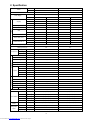
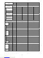
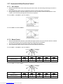
2. Specification
Indoor CS-C7MKP-7 CS-C9MKP-7
Model
Outdoor CU-C7MKP-7 CU-C9MKP-7
Performance Test Condition NEW JIS NEW JIS
Phase, Hz Single, 50 Single, 50
Power Supply
V 220 240 220 240
kW 2.00 2.05 2.65 2.70
BTU/h 6820 6990 9040 9210
Capacity
kJ/h 7200 7380 9540 9720
Running Current A 3.0 3.0 3.8 3.7
Input Power W 590 640 800 835
W/W 3.39 3.20 3.31 3.23
EER
Btu/hW 11.6 10.9 11.3 11.0
Power Factor % 89 89 96 94
dB-A 33 / 26 33 / 26 36 / 26 36 / 26
Indoor Noise (H / L)
Power Level dB 46 / - 46 / - 49 / - 49 / -
dB-A 46 / - 47 / - 46 / - 47 / -
Cooling
Outdoor Noise (H / L)
Power Level dB 61 / - 62 / - 61 / - 62 / -
Max Current (A) / Max Input Power (W) 3.9 / 860 4.8 / 1.09k
Starting Current (A) 12.2 17.0
Type Hermetic Motor Hermetic Motor
Motor Type Induction (2 poles) Induction (2 poles)
Compressor
Output Power W 550 700
Type Cross-Flow Fan Cross-Flow Fan
Material ASG20K1 ASG20K1
Motor Type Induction (4 poles) Induction (4 poles)
Input Power W 38.0 - 42.0 38.0 - 42.0
Output Power W 22 22
QLo rpm 690 - 690 690 - 690
Lo rpm 760 - 760 760 - 760
Me rpm 860 - 860 950 - 950
Hi rpm 960 - 960 1150 - 1150
Indoor Fan
Speed
SHi rpm 1050 - 1050 1170 - 1170
Type Propeller Fan Propeller Fan
Material PP Resin PP Resin
Motor Type Induction (6 poles) Induction (6 poles)
Input Power W 66.0 - 75.0 66.0 - 75.0
Output Power W 30 30
Outdoor Fan
Speed Hi rpm 810 - 840 810 - 840
Moisture Removal L/h (Pt/h) 1.3 (2.7) 1.6 (3.4)
QLo m3/min (ft3/min) 5.7 (201) - 5.7 (201) 5.9 (208) - 5.9 (208)
Lo m3/min (ft3/min) 6.1 (215) - 6.1 (215) 6.3 (223) - 6.3 (223)
Me m3/min (ft3/min) 6.9 (244) - 6.9 (244) 7.9 (280) - 7.9 (280)
Hi m3/min (ft3/min) 7.9 (279) - 7.9 (279) 9.8 (346) - 9.8 (346)
Indoor Airflow
SHi m3/min (ft3/min) 8.6 (305) - 8.6 (305) 10.0 (352) - 10.0 (352)
Outdoor
Airflow Hi m3/min (ft3/min) 28.8 (1020) - 29.6 (1040) 28.8 (1020) - 29.6 (1040)
Control Device Capillary Tube Capillary Tube
Refrigerant Oil cm3 ATMOS M60 or Suniso 4GDID (290) ATMOS M60 or Suniso 4GDID (350)
Refrigeration
Cycle
Refrigerant Type g (oz) R22, 400 (14.1) R22, 470 (16.6)
Downloaded from www.Manualslib.com manuals search engine

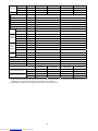
6
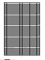
Height(I/D / O/D) mm (inch) 290 (11-7/16) 510 (20-3/32) 290 (11-7/16) 510 (20-3/32)
Width (I/D / O/D) mm (inch) 870 (34-9/32) 650 (25-19/32) 870 (34-9/32) 650 (25-19/32)
Dimension
Depth (I/D / O/D) mm (inch) 204 (8-1/16) 230 (9-1/16) 204 (8-1/16) 230 (9-1/16)
Weight Net (I/D / O/D) kg (lb) 9 (20) 22 (49) 9 (20) 21 (46)
Pipe Diameter (Liquid / Gas) mm (inch) 6.35 (1/4) / 9.52 (3/8) 6.35 (1/4) / 9.52 (3/8)
Standard length m (ft) 7.5 (24.6) 7.5 (24.6)
Length range (min – max) m (ft) 3 (9.8) ~ 10 (32.8) 3 (9.8) ~ 10 (32.8)
I/D & O/D Height different m (ft) 5 (16.4) 5 (16.4)
Additional Gas Amount g/m (oz/ft) 10 (0.1) 10 (0.1)
Piping
Length for Additional Gas m (ft) 7.5 (24.6) 7.5 (24.6)
Inner Diameter mm 16.2 16.2
Drain Hose
Length mm 550 550
Fin Material Aluminium (Pre coated) Aluminium (Pre coated)
Fin Type Slit Fin Slit Fin
Row x Stage x FPI 2 x 10 x 17 2 x 10 x 17
Indoor Heat
Exchanger
Size (W x H x L) mm 610 x 210 x 25.4 610 x 210 x 25.4
Fin Material Aluminium (Blue coated) Aluminium (Blue coated)
Fin Type Slit Fin Slit Fin
Row x Stage x FPI 1 x 23 x 17 1 x 23 x 17
Outdoor
Heat
Exchanger
Size (W x H x L) mm 12.7 x 483 x 578.4 12.7 x 483 x 578.4
Material Polypropelene Polypropelene
Air Filter
Type One-touch One-touch
Power Supply Indoor Indoor
Power Supply Cord A 10 10
Thermostat - -
Protection Device 2-Stage Overload Protector 2-Stage Overload Protector
DRY BULB WET BULB DRY BULB WET BULB
Maximum 32 23 32 23
Indoor Operation Range
Minimum 16 11 16 11
Maximum 43 26 43 26
Outdoor Operation Range
Minimum 16 11 16 11
1. Cooling capacities are based on indoor temperature of 27°C Dry Bulb (80.6°F Dry Bulb), 19.0°C Wet Bulb (66.2°F Wet Bulb) and outdoor air
temperature of 35°C Dry Bulb (95°F Dry Bulb), 24°C Wet Bulb (75.2°F Wet Bulb)
2. Specifications are subjected to change without prior notice for further improvement.
Downloaded from www.Manualslib.com manuals search engine

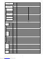
7
Indoor CS-C12MKP-7
Model
Outdoor CU-C12MKP-7
Performance Test Condition NEW JIS
Phase, Hz Single, 50
Power Supply
V 220 240
kW 3.52 3.57
BTU/h 12000 12200
Capacity
kJ/h 12670 12850
Running Current A 5.3 5.2
Input Power W 1.11k 1.15k
W/W 3.17 3.10
EER
Btu/hW 10.8 10.6
Power Factor % 95 92
dB-A 39 / 29 39 / 29
Indoor Noise (H / L / QLo)
Power Level dB 52 / - 52 / -
dB-A 48 / - 49 / -
Cooling
Outdoor Noise (H / L)
Power Level dB 63 / - 64 / -
Max Current (A) / Max Input Power (W) 6.8 / 1.54k
Starting Current (A) 22.0
Type Hermetic Motor
Motor Type Induction (2 poles)
Compressor
Output Power W 950
Type Cross-Flow Fan
Material ASG20K1
Motor Type Induction (4 poles)
Input Power W 47.0 - 50.0
Output Power W 24
QLo rpm 730 - 730
Lo rpm 810 - 810
Me rpm 940 - 940
Hi rpm 1120 - 1120
Indoor Fan
Speed
SHi rpm 1150 - 1150
Type Propeller Fan
Material PP Resin
Motor Type Induction (6 poles)
Input Power W 66.6 - 74.6
Output Power W 30
Outdoor Fan
Speed Hi rpm 830 - 860
Moisture Removal L/h (Pt/h) 2.1 (4.4)
QLo m3/min (ft3/min) 7.2 (253) - 7.2 (253)
Lo m3/min (ft3/min) 7.9 (277) - 7.9 (277)
Me m3/min (ft3/min) 9.2 (326) - 9.2 (326)
Hi m3/min (ft3/min) 10.8 (381) - 10.8 (381)
Indoor Airflow
SHi m3/min (ft3/min) 11.3 (399) - 11.3 (399)
Outdoor
Airflow Hi m3/min (ft3/min) 22.0 (780) - 23.6 (830)
Control Device Capillary Tube
Refrigerant Oil cm3 ATMOS M60 or Suniso 4GDID (350)
Refrigeration
Cycle
Refrigerant Type g (oz) R22, 770 (27.2)
Downloaded from www.Manualslib.com manuals search engine

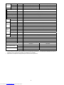
8
Height(I/D / O/D) mm (inch) 290 (11-7/16) 510 (20-3/32)
Width (I/D / O/D) mm (inch) 870 (34-9/32) 650 (25-19/32)
Dimension
Depth (I/D / O/D) mm (inch) 204 (8-1/16) 230 (9-1/16)
Weight Net (I/D / O/D) kg (lb) 9 (20) 25 (55)
Pipe Diameter (Liquid / Gas) mm (inch) 6.35 (1/4) / 12.70 (1/2)
Standard length m (ft) 7.5 (24.6)
Length range (min – max) m (ft) 3 (9.8 ) ~ 15 (49.2)
I/D & O/D Height different m (ft) 5 (16.4)
Additional Gas Amount g/m (oz/ft) 10 (0.1)
Piping
Length for Additional Gas m (ft) 7.5 (24.6)
Inner Diameter mm 16.2
Drain Hose
Length mm 550
Fin Material Aluminium (Pre coated)
Fin Type Slit fin
Row x Stage x FPI 2 x 15 x 17
Indoor Heat
Exchanger
Size (W x H x L) mm 610 x 315 x 25.4
Fin Material Aluminium (Blue Coated)
Fin Type Slit Fin
Row x Stage x FPI 2 x 23 x 17
Outdoor
Heat
Exchanger
Size (W x H x L) mm 25.4 x 483 x 582:562
Material Polypropelene
Air Filter
Type One-touch
Power Supply Indoor
Power Supply Cord A 10
Thermostat -
Protection Device 2-Stage Overload Protector
DRY BULB WET BULB
Maximum 32 23
Indoor Operation Range
Minimum 16 11
Maximum 43 26
Outdoor Operation Range
Minimum 16 11
1. Cooling capacities are based on indoor temperature of 27°C Dry Bulb (80.6°F Dry Bulb), 19.0°C Wet Bulb (66.2°F Wet Bulb) and outdoor air
temperature of 35°C Dry Bulb (95°F Dry Bulb), 24°C Wet Bulb (75.2°F Wet Bulb)
2. Specifications are subjected to change without prior notice for further improvement.
Downloaded from www.Manualslib.com manuals search engine

9
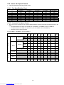
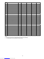
Indoor CS-C18MKP-7 CS-C24MKP-7
Model
Outdoor CU-C18MKP-7 CU-C24MKP-7
Performance Test Condition NEW JIS NEW JIS
Phase, Hz Single, 50 Single, 50
Power Supply
V 220 240 220 240
kW 5.40 5.40 7.03 7.03
BTU/h 18400 18400 24000 24000
Capacity
kJ/h 19440 19440 25310 25310
Running Current A 8.4 8.3 11.0 11.1
Input Power W 1.75k 1.85k 2.35k 2.47k
W/W 3.09 2.92 2.99 2.85
EER
Btu/hW 10.51 9.95 10.21 9.72
Power Factor % 95 93. 97 93
dB-A 43 / 37 43 / 37 46 / 40 46 / 40
Indoor Noise (H / L)
Power Level dB - - - -
dB-A 53 / - 54 / - 54 / - 55 / -
Cooling
Outdoor Noise (H / L)
Power Level dB - - - -
Max Current (A) / Max Input Power (W) 10.7 / 2.41k 14.2 / 3.06k
Starting Current (A) 40.0 60.0
Type Hermetic Motor Hermetic Motor
Motor Type Induction (2 poles) Induction (2 poles)
Compressor
Output Power W 1.5k 2.0k
Type Cross-Flow Fan Cross-Flow Fan
Material ASG30K1 ASG30K1
Motor Type Transistor (8 poles) Transistor (8 poles)
Input Power W 94.8 - 94.8 94.8 - 94.8
Output Power W 40 40
QLo rpm 920 - 920 1020 - 1020
Lo rpm 1010 - 1010 1110 - 1110
Me rpm 1120 - 1120 1230 - 1230
Hi rpm 1240 - 1240 1350 - 1350
Indoor Fan
Speed
SHi rpm 1390 - 1390 1500 - 1500
Type Propeller Fan Propeller Fan
Material PP Resin PP Resin
Motor Type Induction (6 poles) Induction (6 poles)
Input Power W 76.2 - 86.5 134.4 - 152.0
Output Power W 36 66
Lo rpm - 420 - 480
Outdoor Fan
Speed
Hi rpm 830 - 855 740 - 770
Moisture Removal L/h (Pt/h) 2.9 (6.1) 4.0 (8.5)
QLo m3/min (ft3/min) 12.2 (430) - 12.2 (430) 13.8 (486) - 13.8 (486)
Lo m3/min (ft3/min) 13.4 (472) - 13.4 (472) 15.0 (528) - 15.0 (528)
Me m3/min (ft3/min) 14.8 (523) - 14.8 (523) 16.6 (586) - 16.6 (586)
Hi m3/min (ft3/min) 16.4 (579) - 16.4 (579) 18.2 (642) - 18.2 (642)
Indoor Airflow
SHi m3/min (ft3/min) 18.4 (649) - 18.4 (649) 20.2 (714) - 20.2 (714)
Lo m3/min (ft3/min) - 24.8 (880) - 28.5 (1010)
Outdoor
Airflow Hi m3/min (ft3/min) 30.3 (1070) - 31.3 (1100) 45.5 (1610) - 47.5 (1680)
Downloaded from www.Manualslib.com manuals search engine

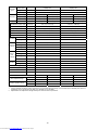
10
Control Device Capillary Tube Capillary Tube
Refrigerant Oil cm3 ATMOS M60 or Suniso 4GDID (450) ATMOS M60 or Suniso 4GDID (700)
Refrigeration
Cycle
Refrigerant Type g (oz) R22, 950 (33.5) R22, 1.20k (42.4)
Height(I/D / O/D) mm (inch) 290 (11-7/16) 540 (21-9/32) 290 (11-7/16) 750 (29-17/32)
Width (I/D / O/D) mm (inch) 1070 (42-5/32) 780 (30-23/32) 1070 (42-5/32) 875 (34-15/32)
Dimension
Depth (I/D / O/D) mm (inch) 235 (9-9/32) 289 (11-13/32) 235 (9-9/32) 345 (13-19/32)
Weight Net (I/D / O/D) kg (lb) 12 (26) 37 (82) 12 (26) 53 (117)
Pipe Diameter (Liquid / Gas) mm (inch) 6.35 (1/4) / 12.70 (1/2) 6.35 (1/4) / 15.88 (5/8)
Standard length m (ft) 5.0 (16.4) 5.0 (16.4)
Length range (min – max) m (ft) 3 (9.8) ~ 25 (82.0) 3 (9.8) ~ 25 (82.0)
I/D & O/D Height different m (ft) 20 (65.6) 20 (65.6)
Additional Gas Amount g/m (oz/ft) 20 (0.2) 30 (0.3)
Piping
Length for Additional Gas m (ft) 7.5 (24.6) 7.5 (24.6)
Inner Diameter mm 16 16
Drain Hose
Length mm 550 550
Fin Material Aluminium (Pre coated) Aluminium (Pre coated)
Fin Type Slit Fin Slit Fin
Row x Stage x FPI 2 x 15 x 21 2 x 15 x 21
Indoor Heat
Exchanger
Size (W x H x L) mm 810 x 315 x 25.4 810 x 315 x 25.4
Fin Material Aluminium (Blue coated) Aluminium (Blue coated)
Fin Type Slit Fin Slit Fin
Row x Stage x FPI 2 x 24 x 17 2 x 34 x 17
Outdoor
Heat
Exchanger
Size (W x H x L) mm 25.4 x 504 x 693.4:713.4 25.4 x 714 x 831.2:811.2
Material Polypropelene Polypropelene
Air Filter
Type One-touch One-touch
Power Supply Indoor Indoor
Power Supply Cord A 16 20
Thermostat - Mechanical
Protection Device Overload Protector -
DRY BULB WET BULB DRY BULB WET BULB
Maximum 32 23 32 23
Indoor Operation Range
Minimum 16 11 16 11
Maximum 43 26 43 26
Outdoor Operation Range
Minimum 16 11 16 11
1. Cooling capacities are based on indoor temperature of 27°C Dry Bulb (80.6°F Dry Bulb), 19.0°C Wet Bulb (66.2°F Wet Bulb) and outdoor air
temperature of 35°C Dry Bulb (95°F Dry Bulb), 24°C Wet Bulb (75.2°F Wet Bulb)
2. Specifications are subjected to change without prior notice for further improvement.
Downloaded from www.Manualslib.com manuals search engine

11
3. Features
E-ion Air Purifying System with Patrol Sensor
o Active e-ions are released to catch dust particles and bring them back the large positively charged filter.
o Patrol Sensor color changes to indicate the dirt level in the air
Long Installation Piping
o CS/CU-C7MK, CS/CU-C9MK, long piping up to 10 meters.
o CS/CU-C12MK, long piping up to 15 meters.
o CS/CU-C18MK, CS/CU-C24MK, long piping up to 25 meters.
Easy to use remote control
Quality Improvement
o Random auto restart after power failure for safety restart operation
o Gas leakage protection
o Prevent compressor reverse cycle
o Inner protector to protect compressor
o Noise prevention during soft dry operation
o Blue coated condenser for high resistance to corrosion
Operation Improvement
o Quiet mode to reduce the indoor unit operating sound
o Powerful mode to reach the desired room temperature quickly
o 24-hour timer setting
Downloaded from www.Manualslib.com manuals search engine


20
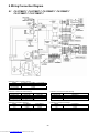
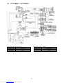
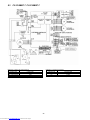
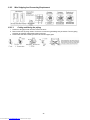
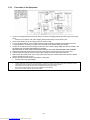
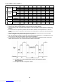
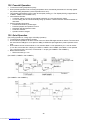
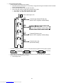
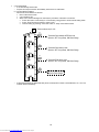
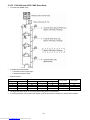
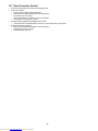
8. Wiring Connection Diagram
8.1 CS-C7MKP-7 CU-C7MKP-7 CS-C9MKP-7 CU-C9MKP-7
CS-C12MKP-7 CU-C12MKP-7
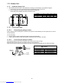
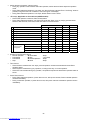
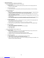
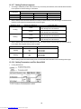
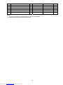
Resistance of Indoor Fan Motor Windings
MODEL CS-C7MKP-7 / CS-C9MKP-7 / CS-C12MKP-7
CONNECTION CWA921434
BLUE-YELLOW 351.3
YELLOW-RED 343.9
Note: Resistance at 25°C of ambient temperature.
Resistance of Outdoor Fan Motor Windings Resistance of Outdoor Fan Motor Windings
MODEL CU-C9MKP-7 CU-C12MKP-7 MODEL CU-C7MKP-7
CONNECTION CWA951691 CWA951691 CONNECTION CWA951673
BLUE-YELLOW 388 388 BLUE-YELLOW 318
YELLOW-RED 305 305 YELLOW-RED 272
Note: Resistance at 20°C of ambient temperature.
Resistance of Compressor Windings Resistance of Compressor Windings
MODEL CU-C9MKP-7 CU-C12MKP-7 MODEL CU-C7MKP-7
CONNECTION 2PS146D3BA06 2PS206D3CA06 CONNECTION 2RS122D5AD02
C-R 5.091 2.878 C-R 5.627
C-S 5.382 5.874 C-S 12.19
Note: Resistance at 20°C of ambient temperature.
Downloaded from www.Manualslib.com manuals search engine
Page is loading ...
Page is loading ...
Page is loading ...
Page is loading ...
Page is loading ...
Page is loading ...
Page is loading ...
Page is loading ...
Page is loading ...
Page is loading ...
Page is loading ...
Page is loading ...
Page is loading ...
Page is loading ...
Page is loading ...
Page is loading ...
Page is loading ...
Page is loading ...
Page is loading ...
Page is loading ...
Page is loading ...
Page is loading ...
Page is loading ...
Page is loading ...
Page is loading ...
Page is loading ...
Page is loading ...
Page is loading ...
Page is loading ...
Page is loading ...
Page is loading ...
Page is loading ...
Page is loading ...
Page is loading ...
Page is loading ...
Page is loading ...
Page is loading ...
Page is loading ...
Page is loading ...
Page is loading ...
Page is loading ...
Page is loading ...
Page is loading ...
Page is loading ...
Page is loading ...
Page is loading ...
Page is loading ...
Page is loading ...
Page is loading ...
Page is loading ...
Page is loading ...
Page is loading ...
Page is loading ...
Page is loading ...
Page is loading ...
Page is loading ...
Page is loading ...
Page is loading ...
Page is loading ...
Page is loading ...
Page is loading ...
Page is loading ...
Page is loading ...
Page is loading ...
Page is loading ...
Page is loading ...
Page is loading ...
Page is loading ...
Page is loading ...
Page is loading ...
Page is loading ...
Page is loading ...
Page is loading ...
Page is loading ...
Page is loading ...
Page is loading ...
Page is loading ...
Page is loading ...
Page is loading ...
-
 1
1
-
 2
2
-
 3
3
-
 4
4
-
 5
5
-
 6
6
-
 7
7
-
 8
8
-
 9
9
-
 10
10
-
 11
11
-
 12
12
-
 13
13
-
 14
14
-
 15
15
-
 16
16
-
 17
17
-
 18
18
-
 19
19
-
 20
20
-
 21
21
-
 22
22
-
 23
23
-
 24
24
-
 25
25
-
 26
26
-
 27
27
-
 28
28
-
 29
29
-
 30
30
-
 31
31
-
 32
32
-
 33
33
-
 34
34
-
 35
35
-
 36
36
-
 37
37
-
 38
38
-
 39
39
-
 40
40
-
 41
41
-
 42
42
-
 43
43
-
 44
44
-
 45
45
-
 46
46
-
 47
47
-
 48
48
-
 49
49
-
 50
50
-
 51
51
-
 52
52
-
 53
53
-
 54
54
-
 55
55
-
 56
56
-
 57
57
-
 58
58
-
 59
59
-
 60
60
-
 61
61
-
 62
62
-
 63
63
-
 64
64
-
 65
65
-
 66
66
-
 67
67
-
 68
68
-
 69
69
-
 70
70
-
 71
71
-
 72
72
-
 73
73
-
 74
74
-
 75
75
-
 76
76
-
 77
77
-
 78
78
-
 79
79
-
 80
80
-
 81
81
-
 82
82
-
 83
83
-
 84
84
-
 85
85
-
 86
86
-
 87
87
-
 88
88
-
 89
89
-
 90
90
-
 91
91
-
 92
92
-
 93
93
-
 94
94
-
 95
95
-
 96
96
-
 97
97
-
 98
98
-
 99
99


Panasonic CS-C18MKP-7 User manual
- Category
- Split-system air conditioners
- Type
- User manual
- This manual is also suitable for
Ask a question and I''ll find the answer in the document
Finding information in a document is now easier with AI
Related papers
-
Panasonic CS-E21JKR Operating Instructions Manual
-
-
-
-
-
Panasonic CS-YU18ZKA User manual
-
Panasonic CU-2RE15MBE User manual
-
Panasonic CS-E12NKEW User manual
-
Panasonic CS-E15NKDW User manual
-
Panasonic CS-S9NKUW-1 User manual
Other documents
-
Fujitsu UTY-RNNUM Air Conditioner Remote Controller User manual
-
Niagara ECO-IQ N9195 Installation & Operating Instructions Manual
-
KDK RXL55H Operating instructions
-
Rasonic RC-N2421E User manual
-
-
Acson ACM 15 ER User manual
-
LG Electronics 5CSV2-03A User manual
-
McQuay MCK040AR User manual
-
Rasonic RC-N1821E User manual
-
Rasonic RC-N921J User manual