
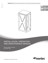
Nortec
SE-Series
Installation and
Operation Manual
Includes installation, operation,
maintenance, and troubleshooting
information for your indoor
Nortec SETC B+ and Nortec SEP
steam exchange humidifier
2552940-F | 31/MAY/2021
Important: Read and save these instructions. This guide to be left with equipment.

Thank you for choosing Condair.
Proprietary Notice
This document and the information disclosed herein are proprietary data of Condair LTD. Neither
this
document nor the information contained herein shall be reproduced used, or disclosed to others without
the
written authorization of Condair LTD., except to the extent required for installation or
maintenance of
recipient’s equipment. All references to the Condair name should be taken as referring to
Condair LTD.
Liability Notice
Condair does not accept any liability for installations of humidity equipment installed by unqualified personnel
or
the use of parts/components/equipment that are not authorized or approved by Condair.
Copyright Notice
Copyright 2021, Condair LTD. All rights reserved.
INSTALLATION DATE (MM/DD/YYYY)
MODEL #
SERIAL #

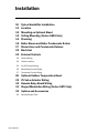
Contents
1
Introduction
2 Receiving and Unpacking
3 Humidifier Components
5 Nortec SETC/P Models
6 Options and Accessories
9
Installation
10 Typical Humidifier Installation
11 Location
12 Mounting
14 Plumbing
15 Boiler Steam and Boiler
Condensate Return
17 Steam Lines and Condensate
Returns
22 Electrical
23 External Controls
32 Options and Accessories
33
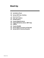
Start Up
34 Installation Check
35 Nortec SETC User Interface
36 Start Up Procedure
37 Status Screens
39 Digital Controls
41 Start Up Checklists
43
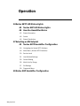
Operation
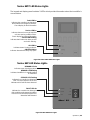
44 Nortec SETC LED Status Lights
44 Nortec SEP LED Status Lights
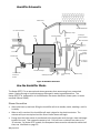
45 How the Humidifier Works
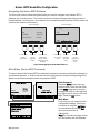
49 Nortec SETC Humidifier Configuration
60 Nortec SEP Humidifier Configuration
63
Maintenance and
Servicing
64 Required Maintenance
65 Maintenance Schedule
69 Maintenance Shutdown and
Extended Shutdown
70 Maintenance Checklist
71
Troubleshooting
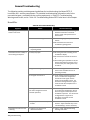
73 General Troubleshooting
76 Nortec SETC Warnings and Faults
82 SEP Faults
83 Wiring Diagrams
85
Spare Parts
96
Warranty

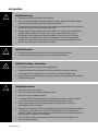
1 | Introduction
Introduction
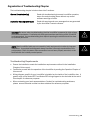
CAUTION: Servicing
• Disconnect main power before any servicing.
• Shut off pressurized steam supply and ensure steam pressure is safely relieved
before any servicing of pressurized steam components.
• The electrical compartment contains high voltage components and wiring. Access
should be limited to authorized personnel only.
• During and following operation of the humidifier, the steam and components in
contact with the steam such as the tank, blower pack, steam lines, steam
distributors, and condensate lines can become hot and can burn if touched.
• Condair does not accept any liability for installations of humidity equipment
installed by unqualified personnel or the use of parts/components/equipment
that are not authorized or approved by Condair.
CAUTION: Electrical
• All electrical work should be done according to local electrical code.
• Electrical connection to be performed by a licensed electrician.
CAUTION: Plumbing / Steam Lines
• Plumbing to be performed by a licensed plumber.
• Pressurized steam line installation to be performed by a qualified installer.
• Drain water from humidifier can be very hot. Do not drain to public sink.
• All plumbing and pressurized steam supply line work should be done according to
local plumbing code.
CAUTION: Installation
• Do not mount on hot surfaces
• Do not mount in area where freezing can occur
• Do not mount on vibrating surface
• The Nortec SETC/P produces steam at atmospheric pressure no devices which
could block steam output should be connected to the steam outlet.
• Steam output lines must be installed so that no restriction can produce
backpressure in the humidifier.
• Regardless of selecting On/Off or modulating control method, Condair humidifiers
must have a closed circuit across its On/Off security loop control terminal to
operate. Condair highly recommends the use of a high limit humidistat and an air
proving switch in series for this function.
• Unit damage caused by water quality outside of the specified ranges is not
covered under warranty.

Introduction | 2
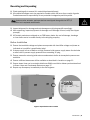
Receiving and Unpacking
1 Check packing slip to ensure ALL material has been delivered.
2 All material shortages are to be reported to Condair within 48 hours from receipt of goods.
Condair assumes no responsibility for any material shortages beyond this period.
3 Inspect shipment for damage and note damages on shipping waybill accordingly.
4 After unpacking, inspect equipment for damage and if damage is found, notify the shipper
promptly.
5 All Condair products are shipped on an FOB factory basis. Any and all damage, breakage
or
loss claims are to be made directly to the shipping company.
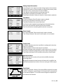
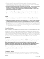
Before Installation
1 Ensure that available voltage and phase corresponds with humidifier voltage and phase as
indicated on humidifier’s specification label.
2 If steam supply is from a Medium or High Pressure boiler ensure supply steam line includes
a relief valve to prevent supply pressure from exceeding 15 psig.
3 Ensure means for returning boiler steam condensate to boiler at atmospheric pressure are
available.
4 Ensure sufficient clearances will be available as described in Location on page 11.
5 Ensure steam lines can be routed to distributor SAM-e manifold or blower pack as described
in Steam Lines and Condensate Returns on page 17.
6 Report any discrepancy immediately to the site engineer.
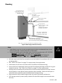
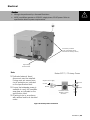
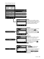
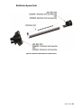
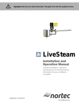
Figure 1: Specification Label Location
Note: A steam valve, actuator, and wye strainer are shipped along with the SETC/P
humidifier but in separate small boxes.

3 | Introduction
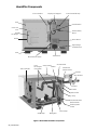
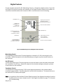
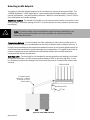
Humidifier Components
Float Chamber
Display and Keypad
Control Terminal Strip
Tank
On/Off Switch
Clean Out
Port
Heat
Exchanger
Gasket
Remote Relay
Board
Driver Board
High Voltage
Terminal Block
Base
Manual Drain Switch
Transformer
Total Controller
Heat
Exchangers
(Faceplate)
Steam Outlet
Fill Box
Vacuum Break
Steam Inlet
(Boiler Steam)
Actuator
Wye Strainer
CV Valve
Fill Valve
Drain Outlet
P Trap
Condensate Drain
(Boiler Steam)
Auxiliary Drain
Outlet
Steam Trap
Mixing Box
Drain Pump
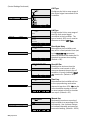
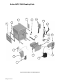
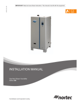
Figure 2: Nortec SETC Humidifier Components

Introduction | 4
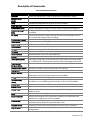
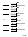
Description of Components
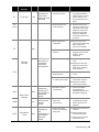
Table 1: Humidifier Components
Component
Function of Component
Actuator
Opens and closes the CV valve in proportion to demand for steam.
Auxiliary Drain
Outlet
Drains water from tank in case of pump failure.
Base
Provides an integrated floor support for the humidifier.
Clean Out Port
Provides access to clean scale from the tank and heat exchanger.
Condensate Drain
Drains condensate formed from boiler steam in the heat exchanger(s)
Control Terminal
Strip
Terminal strip for connecting external controls and blower pack to
humidifier.
CV Valve
Controls the amount of steam allowed into the heat exchanger which in
turn controls the output of the humidifier.
Display and Keypad
User interface for configuring the humidifier.
Drain Outlet
Drain port used for draining water from the humidifier tank.
Drain Pump
Drains water from humidifier.
Driver Board
Provides input and output connections to humidifier components.
Fill Box
Provides an air gap for backflow prevention.
Fill Valve
Controls flow of water into humidifier.
Float Chamber
Measures water level in the humidifier tank.
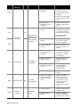
Gasket
Seals heat exchanger face plate and clean out port cover to tank.
Heat Exchanger(s)
Exchanges energy from boiler steam to the tank water to produce steam
for humidification. The faceplate mounts the heat exchanger to the tank.
High Voltage
Terminal Block
Primary power connection from remote disconnect to humidifier.
Manual Drain Switch
Manually activates pump to drain water from the tank.
Mixing Box
Blends hot tank water with cool fill water to provide drain water cooling.
On/Off Switch
Turns power On/Off to humidifier controller. Note: Turn off humidifier
disconnect to shut off primary power to the humidifier.
P Trap
Prevents steam from flowing out the drain outlet.
Remote Relay
Board
Provides a terminal strip to dry contacts which open/close to indicate the
humidifier is on, humidifying, needs service, or is in a fault condition.
Steam Inlet
Connection for boiler steam, it is connected to the heat exchangers.
Steam Outlet
Connect to steam line with steam hose.
Steam Trap
Drains condensate from the heat exchanger without letting boiler steam
escape to drain.
Tank
Holds the water used to generate clean steam for humidification.
Total Controller
Controls all functions of the humidifier’s operation and provides user
interface for configuration of the humidifier.
Transformer
Steps primary voltage down to 24 VAC for the controller and internal
components such as the fill valve and drain valve.
Vacuum Break
Prevents a siphon from occurring when the drain pump is stopped.
Wye Strainer
Protects CV valve and other system components from dirt and rust in the
piping system.

5 | Introduction
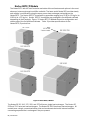
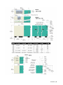
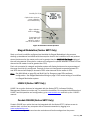
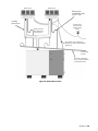
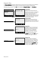
Nortec SETC/P Models
The Nortec SETC with its Total Controller and state-of-the-art features and options is the most
advanced steam exchange humidifier available. The base model Nortec SEP provides steady
and reliable humidification using the same proven heat exchanger technology as the
Nortec SETC. The Nortec SETC/P is available in capacities ranging from 50 lb/hr (23 kg/hr) to
1050 lb/hr (475 kg/hr). Nortec SETC/P humidifiers are packaged in five different cabinets
depending on their capacity. Figure
3: Nortec SETC/P Models shows the configuration and
relative size of the five different cabinets. Table
3 provides specifications for the
Nortec SETC/P product line.
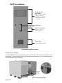
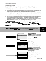
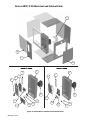
Figure 3: Nortec SETC/P Models
The Nortec SE 50, 100, 175, 250, and 375 all have a single heat exchanger. The Nortec SE
525 and 750 have two heat exchangers. The Nortec SE 1050 has three heat exchangers. All
models have a single pressurized steam inlet and condensate drain with internal manifold
connecting separate heat
exchangers if they are present.
SETC50
Note:
SE 750 has
2 steam outlets
SE 525-750
SE 100-175
SE 1050
SE 250-375

Introduction | 6
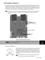
Outdoor Model (Nortec SETC Only)
The outdoor model of the Nortec SETC provides a weatherproof enclosure that allows the Nortec
SETC to be
installed on rooftops in moderately cool climates. Refer to the Nortec SETC
installation manual that is
provided with the outdoor model to insure proper installation.
Options and Accessories
Condair provides a complete line of options and accessories for every humidification application.
The following options and accessories are available and may have been delivered with your
Nortec SETC/P humidifier. Refer to the installation instructions that came with the accessories
for their
proper installation and operation.
Table 2: Options and Accessories
Option / Accessory
Used For
Freeze Protection Package
(Nortec SETC Only)
Emptying the tank in case of fault or power failure to prevent
freezing. (Factory installed)
Floor Stand
Supporting the humidifier 27 inches above the floor (height can be
reduced by cutting legs of floor stand). (field assembled)
Ceiling Mounting Kit (Nortec SE50 Only)
Providing a drain pan and support brackets for mounting an
Nortec SE50
unit from the ceiling.
Steam Distributors
Adding steam into air ducts
Remote Blower Pack
Adding steam into a space remote from the humidifier.
SAM-e Steam Distribution Manifold
Adding steam into air ducts where short absorption is required.
Digital or Analog Control Humidistats
Controlling the output of the humidifier based on sensed RH (can
be mounted in the space being humidified or in the duct).
Digital RH Transducers
Communicating RH in a space or duct to the humidifier
Digital or Analog High Limit Humidistats
Preventing over humidification in a duct by shutting down or
throttling down the humidifier when duct RH gets high.
Air Proving Switches
Insuring humidification only occurs when air is moving in a duct.
Condair LINKS 2 (Nortec SETC Only)
Connecting the humidifier to a building management interface.
hardware allows control of the humidifier via BACnet, Lonworks,
Johnson N2, or Modbus.
Condair OnLine (Nortec SETC Only)
User and factory monitoring and configuration of the humidifier via
the internet.

7 | Installation
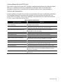
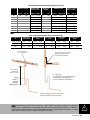
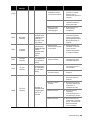
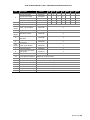
Table 3: Nortec SETC/P Specifications
Nortec
Model
SETC
Part No
SEP
Part No.
CV
Valve
CV Valve,
Steam
Inlet, Wye
Port (NPT)
Cond-
ensate
Port
(NPT)
Net/Full
Weight
lb (kg)
Required
fill line
flow
gal (l)
/min
Required
Drain
capacity
gal (l)
/min
Electrical
50
2552765
2520383
2.8
1/2
3/4
125/180
(57/82)
2.6 (10)
5.2 (20)
Voltage
110-120
100
2550073
2525132
5.5
3/4
3/4
267/423
Phase
1
175
2550074
2525133
10
1
3/4
(121/192)
250
2550075
2525134
12
1
3/4
355/599
Amps
(161/272)
1.25 A
375
2550076
2525135
20
1 1/4
3/4
Power
525
2550077
2553312
28
1 1/2
1
529/992
0.15 KW
750
2550078
2553313
40
2
1
(240/450)
4.5 (17)
8 (29)
Max
1050
2550080
2525139
77
2, 2 1/2,
2 1/2
1 1/4
703/1384
(318/628)
Disconnect
15 A
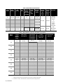
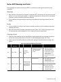
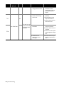
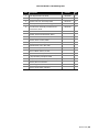
Table 4: Nortec SETC/P Capacities and Water Consumption
Nortec
Model
*Supply
Steam
Pressure
(psig)
*Max Output
lb/hr (kg/hr)
Approximate
Boiler Steam
Consumption
lb/hr (kg/hr)
**Water
Consumption
gal (l) /hr
**Drain Volume
gal (l) /hr
50
5
13 (6)
15 (7)
2.3 (9)
0.8 (3)
10
32 (14)
36 (16)
5.7 (21)
1.9 (7)
15
50 (23)
58 (26)
9.0 (34)
3.0 (11)
100
5
26 (12)
30 (14)
4.7 (18)
1.6 (6)
10
63 (29)
72 (33)
11.3 (43)
3.8 (14)
15
100 (45)
115 (52)
18.0 (68)
6.0 (23)
175
5
46 (21)
52 (24)
8.2 (31)
2.7 (10)
10
110 (50)
127 (58)
19.8 (75)
6.6 (25)
15
175 (80)
201 (91)
31.5 (119)
10.5 (40)
250
5
65 (30)
75 (34)
11.7 (44)
3.9 (15)
10
158 (72)
181 (82)
28.3 (107)
9.4 (36)
15
250 (114)
288 (131)
44.9 (170)
15.0 (57)
375
5
98 (44)
112 (51)
17.5 (66)
5.8 (22)
10
236 (107)
272 (123)
42.5 (161)
14.2 (54)
15
375 (170)
431 (196)
67.4 (255)
22.5 (85)
525
5
137 (62)
157 (71)
24.5 (93)
8.2 (31)
10
331 (150)
380 (173)
59.5 (225)
19.8 (75)
15
525 (239)
604 (274)
94.4 (357)
31.5 (119)
750
5
195 (89)
224 (102)
35.1 (133)
11.7 (44)
10
473 (215)
543 (247)
84.9 (321)
28.3 (107)
15
750 (341)
863 (392)
134.8 (510)
44.9 (170)
1050
5
273 (124)
314 (143)
49.1 (186)
16.4 (62)
10
662 (301)
761 (346)
118.9 (450)
39.6 (150)
15
1050 (477)
1208 (549)
188.7 (714)
62.9 (238)
* Supply steam pressure must be present at the CV valve to achieve rated output
** At maximum output , 25% blow down, and with drain water cooling activated

Installation | 8
Nortec
Nortec
Nortec

9 | Installation
Installation
10
Typical Humidifier Installation
11
Location
12
Mounting on Optional Stand
13
Ceiling Mounting (Nortec SE50 Only)
14
Plumbing
15
Boiler Steam and Boiler Condensate
Return
17
Steam Lines and Condensate Returns
22
Electrical
23
External Controls
23 Control Wiring
23 Control Location
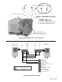
24 On/Off Control Wiring
25 Modulating Control Wiring
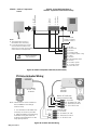
27 Transducer Control Wiring
28
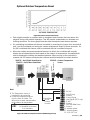
Optional Outdoor Temperature Reset
29
CV Valve Actuator Wiring
30
Remote Relay Board Wiring
31
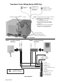
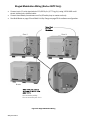
Staged Modulation Wiring (Nortec SETC Only)
32
Options and Accessories
32 Remote Blower Pack

Installation | 10
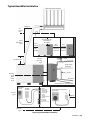
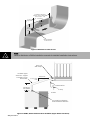
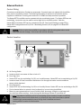
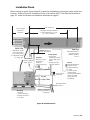
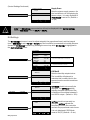
Typical Humidifier Installation
Figure 5: Typical Humidifier Installation
SAM-e Distribution Manifold
1ft (30 cm)
2 in
(5 cm)
min.
Electrical
Pg 22
Controls
Pg 23
Plumbing
Pg 14
Boiler
Steam
Pg 15
1 ft (30 cm) min.
Steam
Distribution
Pg 17
Location
Mounting
Pg 11
30 in
(76 cm)
Min.
SE 1050
36 in (91 cm) min.
Top Clearance
(0 in SE 50)
30 in
(76 cm)
Min. Side
Clearance
30 in
(76 cm)
Min. Front
Clearance
Pressurized steam
supply
Water supply
30-80 psig
Air gap
Tank drain
Condensate return to boiler
Dedicated Circuit Breaker or
Disconnect
SETC/P
EXT
L1
N
Ground
1- 24VAC
2- On/Off Loop
3- Ctrl Ground
4- Control Signal
5- Limit Signal
6- 5 VDC
7- Ground
8- Tank Blow Down
9- Ground
10- Actuator
11- Actuator
12- 0-10 VDC Out
On/Off
Controls
Modulation
Controls
SETC/P
EXT

11 | Installation
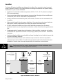
Location
The Nortec SE series humidifiers are designed to be either floor mounted or stand mounted
(stand
optional). Nortec SE 50 models can also be ceiling mounted with the optional ceiling
installation kit, part number 2520345.
• Install only in areas with ambient temperature 41-104 °F (5 – 40 °C) relative humidity 5 -
95% (non condensing).
• Ensure mounting surface is strong enough to support the full weight of the humidifier and
accessories (see Table 3: Nortec SETC/P Specifications).
• Install in location where electrical power, boiler steam, and drain can be connected to the
humidifier.
• When possible install below the steam distributor. If mounted above the steam distributor
take care to provide proper steam line routing and proper condensate traps.
• DO NOT locate the humidifier any further then absolutely necessary from the steam
distributor location as net output will be reduced as a result of heat loss through the steam
line.
• Condensate drain is located close to the bottom of the humidifier. Locate the unit so that
condensate line slopes down to boiler or use pump (by others) to lift to boiler. Use stand if
necessary.
• Avoid mounting humidifier on combustible surfaces including (but not limited to) carpet, tile,
or certain insulating materials.
• Clearance dimensions shown are for reference only and are the minimum required for
maintenance of the humidifier. Consult local and national codes before final location and
installation. Condair does not accept responsibility for installation code violations.
As Close as
Possible to Steam
Distributor
30 in.
(76 cm)
Min.
SE 1050
only
Mount
Humidifier
5-95%
Level
30 in.
(76 cm)
Min. Side
Clearance
Condensate drain
line must be
sloped down, do
not use to lift
condensate
30 in.
(76 cm)
Min. Front
Clearance
36 in. (91 cm) Min.
Top Clearance
(0 in. for SE50 only)
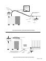
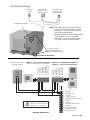
Figure 6: Installation Location / Clearance
Note:. Condensate drain line must be sloped downward to boiler condensate return.
Use pump (by others) or stand (optional) if necessary.

Installation | 12
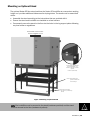
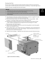
Mounting on Optional Stand
The optional Nortec SE floor stand positions the Nortec SE humidifier at a convenient working
height and
provides additional clearances for sloping drains. The stand must be assembled
at site.
• Assemble the stand according to the instructions that are provided with it.
• Ensure the stand and humidifier are installed on a level surface
• Permanently secure the stand to the floor via the holes in the leg support plates following
any local codes or regulations.
Mount stand on level surface
Ensure humidifier is Level
Figure 7: Mounting on Optional Stand
Fasten Nortec SE humidifier
to stand with bolts, lock
washers, and nuts provided.
Tighten
to 200 in-lb (22.6 Nm).
Note: Center support only
present on Nortec SE
525 and larger.
Secure stand to floor
four places. (hardware by
others)
Note: The humidifier must be secured to the stand (hardware provided) and the stand
must be secured to the floor (hardware by others).

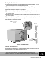
13 | Installation
Ceiling Mounting (Nortec SE50 Only)
12.8 in.
(32.6 cm)
Anchor 3/8 in (M10)
support rods to ceiling
(by others)
Sloped drain
1/2 in. pipe
(by others)
Support rods and hardware
(by others) must not extend
below support bracket flange.
Figure 8: Ceiling Mounting the Nortec SE50
Condair offers an optional ceiling mounting kit (part number 2520345) which allows the Nortec
SE50 to
be ceiling mounted with zero clearance to the ceiling. Follow the following guidelines
for
installation.
• Follow the instructions provided with the ceiling mounting kit.
• Install in a location where regular maintenance can be performed. Provide clearance as
shown in Figure 6: Installation Location / Clearance.
• The Nortec SE50 weighs 180 lb (82 kg) when filled with water and without any
accessories or
piping. It is the installer’s responsibility to calculate the total weight
which must be supported, to ensure the ceiling structure is adequate, and to install
support rods and to
connect drain pan per local codes and regulations.
• The humidifier cannot be used as a structural member. All piping connected to the unit
must be supported independently.
• A drain line emptying into an open drain must be connected to the ceiling kit drain pan.
Condair recommends a 1/2 in. pipe with sufficient slope to ensure any water collected in
the
pan will drain from it.
Note:. The Nortec SE50 requires regular maintenance including removal of scale
from the heat exchanger and tank. Make sure it is installed in a location where
the maintenance can be performed.

Installation | 14
Plumbing
0.75 in. (19 mm). OD
un-threaded drain outlet
Connect with hose cuff
and hose clamps.
1/2 in. NPT
Use union to connect
supply pipe to unit.
Always install a water
shut-off valve.
Air gap required.
2 1/2 in. to 1 1/4 in. copper
reducer is ideal.
Hose/line must not touch
the bottom of the funnel.
Min. 1 1/4 in. OD drain line.
Slope down. Increase size
if combining multiple drains.
Axillary drain, 1/2 in. female NPT
For draining tank without pump. Leave
valve closed except if freeze protection is installed.
*Pipe, unions, and water shut-off valve not supplied by Condair.
Figure 9: Water Supply and Drain Connection
• All water supply and drain line connections must be installed in accordance with local
plumbing codes.
• See Table 3 and Table 4 on page 7 for supply water flow requirements.
• Install water shut off valve and union before humidifier to facilitate servicing.
• Insure drain line is adequately sized to provide free and easy draining and that an air gap is
installed as shown. See Table 3 and Table 4 on page 7 for flow requirements.
• Auxiliary drain connection with manual shut off valve is recommended for all units. Valve to
be left closed on units without freeze protection option installed. Valve to be left open on
units with freeze protection option installed except during servicing.
• High hardness or silica content supply water may require increased maintenance.
• Unit damage caused by water quality outside of the specified ranges is not covered under
warranty.
Note:
• Drain Water is very hot, do not use plastic pipe for drain or condensate lines, do not
drain to public sink. Route to floor drain or equivalent.
• Supply cold potable water, deionized water or reverse osmosis water at 30 - 80 PSIG.
Hardness 5-7 grain or 90 – 120 mg/l (as Ca
+2
as CaCO
3
)
Total Dissolved Solvents (TDS) 0.5-3 mg/l or Conductivity 1 to 70 mho/cm
Chlorides 0-25 ppm PH 7.2-8.5 Alkalinity 30-130 mg/l (as CaCO
3
)

15 | Installation
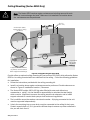
6 in.
(15 cm)
Max
Boiler steam supply
line. Max 15 psi, Min 5 psi
measured at CV Valve
Boiler steam
Actuator
inlet port location
on Nortec SE 1050
CV Valve
(see table 3)
Pressure
gauge (optional)
F&T Trap
Wye Strainer
Isolation Valve
Boiler steam
inlet port
(see table 3)
Condensate Drain
Port (see table 3)
Condensate drain line.
Gravity feed to boiler.
Use pump if condensate
must be lifted.
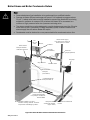
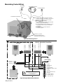
Boiler Steam and Boiler Condensate Return
Note: Condair supplies CV valve,
actuator and wye strainer. All other
components and fittings by others.
Not pressurized
condensate header
(slope down)
Pressurized condensate
header
Figure 10: Nortec SE Boiler Steam and Condensate Connection
Note:.
• Pressurized steam line installation to be performed by a qualified installer.
• Damage to Nortec SE heat exchanger will occur if it is exposed to pressure above
20 psi.. A safety relief valve must be installed to prevent the Nortec SE from being
exposed to pressure in excess of 15 psi when the Nortec SE is connected to a
medium or high pressure boiler via a pressure reducing valve.
• The steam supply line must be designed to provide design pressure at the CV valve
when there is 100 % demand (CV valve completely open). Pressure losses in the
steam supply line will reduce Nortec SE output.
• Condensate must be drained to a non-pressurized boiler condensate return line.

Installation | 16
Condair supplies a CV valve, actuator and wye strainer with each Nortec SE humidifier. The port
sizes of
the CV valve, boiler steam inlet port, and condensate drain port are given in Table
3: Nortec SETC/P Specifications on page 7. Follow the following guidelines for installation.
• All steam line connections must be installed in accordance with local codes.
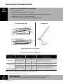
• Install the CV valve actuator following the procedure in Figure 11: CV Valve Actuator
Installation after the CV valve is installed on the steam line. Wire the actuator as described
in CV Valve Actuator Wiring on page 29.
• Boiler steam supply line design is the responsibility of the installer. The boiler steam supply
line must be designed so that that design pressure is present at the CV valve when the CV
valve is completely open (100% demand). The diameter of the supply line up to the wye
strainer may have to be oversized to insure proper steam pressure.
• The Nortec SE will operate on supply steam pressures between 5 and 15 psi measured at
the CV
valve. Lower steam supply pressures will result in lower output. See Table
4: Nortec SETC/P Capacities and Water Consumption on page 7 for capacities at different
supply pressures.
• If condensate cannot be gravity fed to the boiler then a pump must be used to lift the
condensate. See Spirax Sarco (www.spiraxsarco.com) and others for pumps and additional
information on condensate management.
• The boiler steam and condensate connections are independent. Boiler steam condensate
should be returned to the boiler and should not be mixed with water from the tank drain.
• The steam supply pressure can be entered into the Nortec SETC control software to provide
display
of unit output. See Pressure Based on page 56.
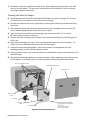
Install jam nut
and lock washer
Install stem
extension
Actuator
2 turns then
push in and
1/8 turn to lock
Raise valve
stem to full up
1/2 in. (1.2 cm)
min.
CV Valve
Install and
tighten
mounting nut
Turn stem
extension
until holes
line up
Insert
connecting
pin
Tighten jam nut
against stem extension
Figure 11: CV Valve Actuator Installation
Caution: Condensate leaves the steam traps inside the Nortec SE under slight pressure.
Steam flash could occur in the condensate drain line.

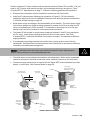
17 | Installation
St
eam
Dire
ction
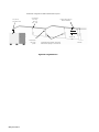
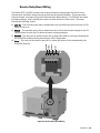
Steam Lines and Condensate Returns
Use Appropriate Slope Insulate Pipe
2 Degrees
0.5 in.
(12 mm)
1ft (30 cm)
1 in. (2.5 cm) pipe
insulation
Figure 12: Main Steam Line Requirements
Table 5: Recommended Steam Line Material
Steam Line
Material
Lb/hr (kg/hr)
Steam Line Length
ft
m
Steam Line Description
Copper Tube
0-100 (0-45)
0-90
0-27
1 1/2 in. MED-L Tubing (1.625 in. OD)
101-250 (46-113)
0-180
0-54
3 in. MED-L Tubing (3.125 in. OD)
251-650 (114-295)
0-260
0-79
**4 in. MED-L Tubing (4.125 in. OD)
*Stainless Steel
Tube
0-100 (0-45)
0-90
0-27
1.75 inch Tube x 0.065 inch thick wall
101-250 (46-113)
0-180
0-54
3 inch Tube x 0.065 inch thick wall
251-650 (114-295)
0-260
0-79
**4 inch Tube x 0.065 inch thick wall
Condair Hose
31-100 (14-45)**
<15
<4.5
***Part Number 1328820 (1 3/4”)
Note: * Use only stainless steel tube for reverse osmosis and deionized water applications.
** Use 2 x 4 in. steam lines for steam capacities higher than 750 lb/hr (307 kg/hr)
*** Use one steam hose per 100 lb/hr (45 kg/hr) of output.
10 Degrees
2 in.
(5 cm)
1 ft (30 cm)
MAIN RULES FOR ATMOSPHERIC STEAM LINES
• Slope the steam lines.
• Trap condensate (Use full size ‘T’ for Traps).
• Steam lines must not have any restrictions which could cause back pressure.
• Insulate with 1.0 in. (2.5 cm) pipe insulation.
• Follow recommended materials, size and length see tables.
Steam Hose Odour: Condair hose may generate a slight odour during initial use.
This odour is temporary and will disappear after a short period of time.
Page is loading ...
Page is loading ...
Page is loading ...
Page is loading ...
Page is loading ...
Page is loading ...
Page is loading ...
Page is loading ...
Page is loading ...
Page is loading ...
Page is loading ...
Page is loading ...
Page is loading ...
Page is loading ...
Page is loading ...
Page is loading ...
Page is loading ...
Page is loading ...
Page is loading ...
Page is loading ...
Page is loading ...
Page is loading ...
Page is loading ...
Page is loading ...
Page is loading ...
Page is loading ...
Page is loading ...
Page is loading ...
Page is loading ...
Page is loading ...
Page is loading ...
Page is loading ...
Page is loading ...
Page is loading ...
Page is loading ...
Page is loading ...
Page is loading ...
Page is loading ...
Page is loading ...
Page is loading ...
Page is loading ...
Page is loading ...
Page is loading ...
Page is loading ...
Page is loading ...
Page is loading ...
Page is loading ...
Page is loading ...
Page is loading ...
Page is loading ...
Page is loading ...
Page is loading ...
Page is loading ...
Page is loading ...
Page is loading ...
Page is loading ...
Page is loading ...
Page is loading ...
Page is loading ...
Page is loading ...
Page is loading ...
Page is loading ...
Page is loading ...
Page is loading ...
Page is loading ...
Page is loading ...
Page is loading ...
Page is loading ...
Page is loading ...
Page is loading ...
Page is loading ...
Page is loading ...
Page is loading ...
Page is loading ...
Page is loading ...
Page is loading ...
Page is loading ...
Page is loading ...
Page is loading ...
Page is loading ...
-
 1
1
-
 2
2
-
 3
3
-
 4
4
-
 5
5
-
 6
6
-
 7
7
-
 8
8
-
 9
9
-
 10
10
-
 11
11
-
 12
12
-
 13
13
-
 14
14
-
 15
15
-
 16
16
-
 17
17
-
 18
18
-
 19
19
-
 20
20
-
 21
21
-
 22
22
-
 23
23
-
 24
24
-
 25
25
-
 26
26
-
 27
27
-
 28
28
-
 29
29
-
 30
30
-
 31
31
-
 32
32
-
 33
33
-
 34
34
-
 35
35
-
 36
36
-
 37
37
-
 38
38
-
 39
39
-
 40
40
-
 41
41
-
 42
42
-
 43
43
-
 44
44
-
 45
45
-
 46
46
-
 47
47
-
 48
48
-
 49
49
-
 50
50
-
 51
51
-
 52
52
-
 53
53
-
 54
54
-
 55
55
-
 56
56
-
 57
57
-
 58
58
-
 59
59
-
 60
60
-
 61
61
-
 62
62
-
 63
63
-
 64
64
-
 65
65
-
 66
66
-
 67
67
-
 68
68
-
 69
69
-
 70
70
-
 71
71
-
 72
72
-
 73
73
-
 74
74
-
 75
75
-
 76
76
-
 77
77
-
 78
78
-
 79
79
-
 80
80
-
 81
81
-
 82
82
-
 83
83
-
 84
84
-
 85
85
-
 86
86
-
 87
87
-
 88
88
-
 89
89
-
 90
90
-
 91
91
-
 92
92
-
 93
93
-
 94
94
-
 95
95
-
 96
96
-
 97
97
-
 98
98
-
 99
99
-
 100
100


Condair SE series Installation guide
- Type
- Installation guide
- This manual is also suitable for
Ask a question and I''ll find the answer in the document
Finding information in a document is now easier with AI
Related papers
-
Condair SE series Installation guide
-
Condair 2552939-C SETC Outdoor Installation guide
-
-
Condair 2575258-B SE Series Installation guide
-
-
-
-
-
-
Other documents
-
 Nortec RS Series Installation, Operation and Maintenance Manual
-
Nortec RH Space 2548758 Operating instructions
-
 Nortec SE 525 Operating instructions
-
 Thermolec ACU-STEAM User And Maintenance Manual
-
 Nortec livesteam Operating instructions
-
Xiaomi Zhimi UVGI Air Humidifier User manual
-
 Nortec GS Installation guide
-
Liebert SL-14050 User manual
-
MrSteam Digital Blowdown Timer Installation & Operation Manual
-


