Page is loading ...

2U Rackmount Server
RS720-E7-RS24-EG
User Guide

ii
Copyright © 2013 ASUSTeK COMPUTER INC. All Rights Reserved.
No part of this manual, including the products and software described in it, may be reproduced, transmitted,
transcribed, stored in a retrieval system, or translated into any language in any form or by any means,
except documentation kept by the purchaser for backup purposes, without the express written permission
of ASUSTeK COMPUTER INC. (“ASUS”).
ASUS provides this manual “as is” without warranty of any kind, either express or implied, including but not
limited to the implied warranties or conditions of merchantability or tness for a particular purpose. In no
event shall ASUS, its directors, ofcers, employees, or agents be liable for any indirect, special, incidental,
or consequential damages (including damages for loss of prots, loss of business, loss of use or data,
interruption of business and the like), even if ASUS has been advised of the possibility of such damages
arising from any defect or error in this manual or product.
Specications and information contained in this manual ae furnished for informational use only, and are
subject to change at any time without notice, and should not be construed as a commitment by ASUS.
ASUS assumes no responsibility or liability for any errors or inaccuracies that may appear in this manual,
including the products and software described in it.
Product warranty or service will not be extended if: (1) the product is repaired, modied or altered, unless
such repair, modication of alteration is authorized in writing by ASUS; or (2) the serial number of the
product is defaced or missing.
Products and corporate names appearing in this manual may or may not be registered trademarks or
copyrights of their respective companies, and are used only for identication or explanation and to the
owners’ benet, without intent to infringe.
E8411
First Edition
July 2013

iii
Contents
Notices ....................................................................................................... viii
REACH ......................................................................................... viii
Safety information ...................................................................................... ix
Australia statement notice ..................................................................x
About this guide ......................................................................................... xi
Chapter 1: Product introduction
1.1 System package contents ........................................................... 1-2
1.2 Serial number label ...................................................................... 1-3
1.3 Systemspecications ................................................................. 1-4
1.4 Front panel features ..................................................................... 1-6
1.5 Rear panel features ...................................................................... 1-6
1.6 Internal features ........................................................................... 1-7
1.7 LED information ........................................................................... 1-8
1.7.1 Front panel LEDs ............................................................ 1-8
1.7.2 HDD status LEDs ............................................................ 1-9
1.7.3 SSD status LEDs ............................................................ 1-9
1.7.4 LAN (RJ-45) LEDs ........................................................ 1-10
1.7.5 SFP+ status LEDs ......................................................... 1-10
Chapter 2: Hardware setup
2.1 Chassis cover ............................................................................... 2-2
2.2 Air Duct ........................................................................................ 2-3
2.3 Central Processing Unit (CPU) ................................................... 2-4
2.3.1 Installing the CPU ........................................................... 2-4
2.3.2 Installing the CPU heatsink ............................................. 2-9
2.4 System memory ......................................................................... 2-10
2.4.1 Overview ....................................................................... 2-10
2.4.2 Memory Congurations ................................................. 2-10
2.4.3 Installing a DIMM on a single clip DIMM socket ........... 2-15
2.5 Hard disk drives (HDDs) ............................................................ 2-16
2.6 Expansion slot ............................................................................ 2-20
2.6.1 Installing an expansion card ........................................ 2-20
2.6.2 Conguring an expansion card ..................................... 2-21
2.7 Cable connections ..................................................................... 2-22

iv
Contents
2.8 System fans ................................................................................ 2-23
2.9 ASUS PIKE card (Optional) ....................................................... 2-25
2.10 Redundant power supply module (Optional) .......................... 2-26
Chapter 3: Installation options
3.1 Friction Rail Kit Installation Guide ............................................. 3-2
3.1.1 Attaching the xing latches to the server ........................ 3-2
Chapter 4: Motherboard Info
4.1 Motherboard layout ...................................................................... 4-2
4.2 Jumpers ........................................................................................ 4-4
4.3 Internal connectors ...................................................................... 4-9
4.4 Onboard LEDs ............................................................................ 4-17
Chapter 5: BIOS setup
5.1 Managing and updating your BIOS ............................................ 5-2
5.1.1 ASUS CrashFree BIOS 3 utility ...................................... 5-2
5.1.2 ASUS EZ Flash 2 Utility .................................................. 5-3
5.1.3 BUPDATER utility............................................................ 5-4
5.2 BIOS setup program .................................................................... 5-6
5.2.1 BIOS menu screen .......................................................... 5-7
5.2.2 Menu bar ......................................................................... 5-7
5.2.3 Menu items ..................................................................... 5-8
5.2.4 Submenu items ............................................................... 5-8
5.2.5 Navigation keys ............................................................... 5-8
5.2.6 General help ................................................................... 5-8
5.2.7 Conguration elds ......................................................... 5-8
5.2.8 Pop-up window ............................................................... 5-8
5.2.9 Scroll bar ......................................................................... 5-8
5.3 Main menu .................................................................................... 5-9
5.3.1 System Date [Day xx/xx/xxxx] ......................................... 5-9
5.3.2 System Time [xx:xx:xx] ................................................... 5-9
5.4 Advanced menu ......................................................................... 5-10
5.4.1 CPU Conguration ........................................................ 5-10
5.4.2 CPU Power Management Conguration ....................... 5-12
5.4.3 Chipset Conguration ................................................... 5-14
5.4.4 PCH SATA Conguration .............................................. 5-19
5.4.5 PCI Subsystem Settings ............................................... 5-21

v
Contents
5.4.6 Intel TXT(LT-SX) Conguration ..................................... 5-24
5.4.7 USB Conguration ........................................................ 5-25
5.4.8 Trusted Computing ........................................................ 5-26
5.4.9 ACPI Settings ................................................................ 5-27
5.4.10 WHEA Conguration ..................................................... 5-28
5.4.11 APM .............................................................................. 5-28
5.4.12 Serial Port Console Redirection .................................... 5-29
5.4.13 Onboard Broadcom 10G Conguration ........................ 5-31
5.4.14 Onboard LAN Conguration .......................................... 5-32
5.4.15 ME Subsystem .............................................................. 5-32
5.4.16 Onboard Devices Conguration .................................... 5-33
5.4.17 Runtime Error Logging Support .................................... 5-34
5.4.18 Network Stack ............................................................... 5-34
5.5 Server Mgmt menu ..................................................................... 5-35
5.5.1 System Event Log ......................................................... 5-36
5.5.2 BMC network conguration ........................................... 5-36
5.5.3 IPv6 BMC Network conguration .................................. 5-37
5.6 Event Logs menu ....................................................................... 5-38
5.6.1 Change Smbios Event Log Settings ............................. 5-38
5.6.2 View Smbios Event Log ................................................ 5-39
5.6.3 View System Event Log ................................................ 5-39
5.7 Boot menu .................................................................................. 5-40
5.8 Monitor menu ............................................................................. 5-43
5.9 Security menu ............................................................................ 5-44
5.10 Tool menu ................................................................................... 5-47
5.11 Exit menu .................................................................................... 5-47
Chapter6: RAIDconguration
6.1 Setting up RAID ............................................................................ 6-2
6.1.1 RAID denitions .............................................................. 6-2
6.1.2 Installing hard disk drives ................................................ 6-3
6.1.3 Setting the RAID item in BIOS ........................................ 6-3
6.1.4 RAID conguration utilities .............................................. 6-3

vi
Contents
6.2 LSISoftwareRAIDCongurationUtility ................................... 6-4
6.2.1 Creating a RAID set ........................................................ 6-5
6.2.2 Adding or viewing a RAID conguration ........................6-11
6.2.3 Initializing the virtual drives ........................................... 6-12
6.2.4 Rebuilding failed drives ................................................. 6-16
6.2.5 Checking the drives for data consistency ..................... 6-18
6.2.6 Deleting a RAID conguration ....................................... 6-21
6.2.7 Selecting the boot drive from a RAID set ...................... 6-22
6.2.8 Enabling WriteCache .................................................... 6-23
6.3 Intel® Rapid Storage Technology enterprise
SATA Option ROM Utility ........................................................... 6-24
6.3.1 Creating a RAID set ...................................................... 6-25
6.3.2 Deleting a RAID set ...................................................... 6-27
6.3.3 Resetting disks to Non-RAID ........................................ 6-28
6.3.4 Exiting the Intel® Rapid Storage Technology enterprise
SATA Option ROM utility ............................................... 6-29
6.3.5 Rebuilding the RAID ..................................................... 6-29
6.3.6 Setting the Boot array in the BIOS Setup Utility ............ 6-31
6.4 Intel® Rapid Storage Technology enterprise (Windows) ........ 6-32
6.4.1 Creating a RAID set ...................................................... 6-33
6.4.2 Changing a Volume Type .............................................. 6-35
6.4.3 Deleting a volume ......................................................... 6-36
6.4.4 Preferences ................................................................... 6-37
Chapter 7: Driver installation
7.1 RAID driver installation ............................................................... 7-2
7.1.1 Creating a RAID driver disk ............................................ 7-2
7.1.2 Installing the RAID controller driver ................................ 7-4
7.2 Intel® chipset device software installation ............................... 7-14
7.3 Intel® Network Connections Software installation .................. 7-16
7.4 VGA driver installation............................................................... 7-19
7.5 Installing the Intel® I350-AM4/I350-AM2/I210
Gigabit Adapter driver ............................................................... 7-22

vii
7.6 Installing the Broadcom 10G driver ......................................... 7-26
7.7 Management applications and utilities installation ................ 7-28
7.8 Running the Support DVD ........................................................ 7-28
7.9 Microsoft .NET Framework 3.5 SP1 .......................................... 7-32
7.10 Intel® Rapid Storage Technology
enterprise 3.0 installation .......................................................... 7-33
ASUS contact information .......................................................................A-1
viii
Notices
Federal Communications Commission Statement
This device complies with Part 15 of the FCC Rules. Operation is subject to the
following two conditions:
• This device may not cause harmful interference, and
• This device must accept any interference received including interference that
may cause undesired operation.
This equipment has been tested and found to comply with the limits for a Class
A digital device, pursuant to Part 15 of the FCC Rules. These limits are designed
to provide reasonable protection against harmful interference in a residential
installation. This equipment generates, uses and can radiate radio frequency
energy and, if not installed and used in accordance with manufacturer’s instructions,
may cause harmful interference to radio communications. However, there is no
guarantee that interference will not occur in a particular installation. If this equipment
does cause harmful interference to radio or television reception, which can be
determined by turning the equipment off and on, the user is encouraged to try to
correct the interference by one or more of the following measures:
• Reorient or relocate the receiving antenna.
• Increase the separation between the equipment and receiver.
• Connect the equipment to an outlet on a circuit different from that to which the
receiver is connected.
• Consult the dealer or an experienced radio/TV technician for help.
Canadian Department of Communications Statement
This digital apparatus does not exceed the Class A limits for radio noise emissions
from digital apparatus set out in the Radio Interference Regulations of the
Canadian Department of Communications.
This Class A digital apparatus complies with Canadian ICES-003.
WARNING! The use of shielded cables for connection of the monitor to the
graphics card is required to assure compliance with FCC regulations. Changes
or modications to this unit not expressly approved by the party responsible for
compliance could void the user’s authority to operate this equipment.
REACH
Complying with the REACH (Registration, Evaluation, Authorization, and Restriction
of Chemicals) regulatory framework, we publish the chemical substances in our
products at ASUS REACH website at http://csr.asus.com/english/REACH.htm.

ix
Safety information
Electrical Safety
• Before installing or removing signal cables, ensure that the power cables for
the system unit and all attached devices are unplugged.
• To prevent electrical shock hazard, disconnect the power cable from the
electrical outlet before relocating the system.
• When adding or removing any additional devices to or from the system, ensure
that the power cables for the devices are unplugged before the signal cables
are connected. If possible, disconnect all power cables from the existing
system before you add a device.
• If the power supply is broken, do not try to x it by yourself. Contact a qualied
service technician or your dealer.
Operation Safety
• Any mechanical operation on this server must be conducted by certied or
experienced engineers.
• Before operating the server, carefully read all the manuals included with the
server package.
• Before using the server, ensure all cables are correctly connected and the
power cables are not damaged. If any damage is detected, contact your dealer
as soon as possible.
• To avoid short circuits, keep paper clips, screws, and staples away from
connectors, slots, sockets and circuitry.
• Avoid dust, humidity, and temperature extremes. Place the server on a stable
surface.
Lithium-Ion Battery Warning
CAUTION! Danger of explosion if battery is incorrectly replaced. Replace
only with the same or equivalent type recommended by the manufacturer.
Dispose of used batteries according to the manufacturer’s instructions.
CD-ROM Drive Safety Warning
CLASS 1 LASER PRODUCT
Heavy System
CAUTION! This server system is heavy. Ask for assistance when moving or
carrying the system.
This product is equipped with a three-wire power cable and plug for the user’s
safety. Use the power cable with a properly grounded electrical outlet to avoid
electrical shock.
x
DO NOT throw the motherboard in municipal waste. This product has been
designed to enable proper reuse of parts and recycling. This symbol of the
crossed out wheeled bin indicates that the product (electrical and electronic
equipment) should not be placed in municipal waste. Check local regulations for
disposal of electronic products.
DO NOT throw the mercury-containing button cell battery in municipal waste.
This symbol of the crossed out wheeled bin indicates that the battery should not
be placed in municipal waste.
Australia statement notice
From 1 January 2012 updated warranties apply to all ASUS products, consistent
with the Australian Consumer Law. For the latest product warranty details please
visit http://support.asus.com. Our goods come with guarantees that cannot be
excluded under the Australian Consumer Law. You are entitled to a replacement or
refund for a major failure and compensation for any other reasonably foreseeable
loss or damage. You are also entitled to have the goods repaired or replaced if the
goods fail to be of acceptable quality and the failure does not amount to a major
failure.
If you require assistance please call ASUS Customer Service 1300 2787 88 or visit
us at http://support.asus.com

xi
About this guide
Audience
This user guide is intended for system integrators, and experienced users with at
least basic knowledge of conguring a server.
Contents
This guide contains the following parts:
1. Chapter 1: Product introduction
This chapter describes the general features of the server, including sections
on front panel and rear panel specications.
2. Chapter 2: Hardware setup
This chapter lists the hardware setup procedures that you have to perform
when installing or removing system components.
3. Chapter 3: Installation options
This chapter describes how to install optional components into the barebone
server.
4. Chapter 4: Motherboard information
This chapter gives information about the motherboard that comes with the
server. This chapter includes the motherboard layout, jumper settings, and
connector locations.
5. Chapter 5: BIOS information
This chapter tells how to change system settings through the BIOS Setup
menus and describes the BIOS parameters.
6. Chapter6:RAIDconguration
This chapter tells how to change system settings through the BIOS Setup
menus. Detailed descriptions of the BIOS parameters are also provided.
7 Chapter 7: Driver installation
This chapter provides instructions for installing the necessary drivers for
different system components.

xii
References
Refer to the following sources for additional information, and for product and
software updates.
1. ASUS Server Web-based Management (ASWM) user guide
This manual tells how to set up and use the proprietary ASUS server
management utility.
2. ASUS websites
The ASUS websites worldwide provide updated information for all ASUS
hardware and software products. Refer to the ASUS contact information.
Conventions
To ensure that you perform certain tasks properly, take note of the following
symbols used throughout this manual.
Typography
Bold text Indicates a menu or an item to select.
Italics
Used to emphasize a word or a phrase.
<Key> Keys enclosed in the less-than and greater-than
sign means that you must press the enclosed key.
Example: <Enter> means that you must press
the Enter or Return key.
<Key1>+<Key2+<Key3> If you must press two or more keys simultaneously,
the key names are linked with a plus sign (+).
Example: <Ctrl>+<Alt>+<Del>
Command Means that you must type the command
exactly as shown, then supply the required
item or value enclosed in brackets.
Example: At the DOS prompt, type the
command line: format A:/S
DANGER/WARNING: Information to prevent injury to yourself when
trying to complete a task.
CAUTION: Information to prevent damage to the components when
trying to complete a task.
NOTE: Tips and additional information to help you complete a task.
IMPORTANT: Instructions that you MUST follow to complete a task.

1-
This chapter describes the general features
of the chassis kit. It includes sections on
front panel and rear panel specications.
Chapter 1
Product introduction

Chapter 1: Product introduction
1-2
*ASUS System Web-based Management
If any of the above items is damaged or missing, contact your retailer.
1.1 System package contents
Check your system package for the following items.
Model Name RS720-E7-RS24-EG
Chassis ASUS R20B 2U Rackmount Chassis
Motherboard Z9PE-D16-10G/DUAL Server Board
Component
1 x 770W Redundant Power Supply (80 PLUS Gold)
1 x SAS/SATA Backplane Board
1 x Front I/O Board
1 x Front USB Card
1 x Power Sharing Board
4 x Easy-swap System Fans
24 x Hot-swap 2.5-inch HDD tray
2 x Hot-swap 2.5-inch SSD tray
Accessories
1 x RS720-E7-RS24-EG User’s Guide
1 x RS720-E7-RS24-EG Support CD
1 x ASWM Enterprise Support CD
1 x ASMB6 - iKVM Support DVD
1 x ASMB6 - iKVM Manual
2 x CPU Heatsink
2 x Bag of Screws
2 x AC Power Cables
Optional Items
1 x Friction Rail Kit
1 x 770W Redundant Power Supply (80 PLUS Gold)
1 x ASUS PIKE 2108-32PD HW RAID card
1 x ASUS PIKE 2208 8-port HW RAID card
1 x ASUS PIKE 2308 8-port RAID card

ASUS RS720-E7-RS24-EG 1-3
1.2 Serial number label
Before requesting support from the ASUS Technical Support team, you must take note of
the product’s serial number containing 14 characters such as xxS0xxxxxxxxxx shown as the
gure below. With the correct serial number of the product, ASUS Technical Support team
members can then offer a quicker and satisfying solution to your problems.
xxS0xxxxxxxxxx
RS720-E7-RS24-EG

Chapter 1: Product introduction
1-4
1.3 Systemspecications
The ASUS RS720-E7-RS24-EG is a 2U barebone server system featuring the
Z9PE-D16-10G/DUAL server board. The server supports two Intel® LGA 2011 Intel®
Xeon® processor E5-2600 / E5-2600 V2 product family plus other latest technologies through
the chipsets onboard.
(continued on the next page)
* Refer to www.asus.com for the complete list of supported memory modules.
Model Name RS720-E7-RS24-EG
Processor Support / System
Bus
2 x Socket LGA 2011
Intel® Xeon® processor E5-2600 / E5-2600 V2 product
family
QPI 6.4 /7.2 / 8.0 GT/s
Core Logic Intel® C602-A
Form Factor EEB, 12 in. x 13 in.
Memory
Total Slots 16 (4 channels per CPU, 8 DIMM per CPU)
Capacity
Maximum up to 128GB (UDIMM)
Maximum up to 512GB (RDIMM)
Maximum up to 512GB (LRDIMM)
Memory Type
DDR3 800/1066/1333/1600 RDIMM
DDR3 1066/1333 ECC UDIMM/Non-ECC UDIMM
DDR3 1066/1333 LR-DIMM
Memory Size
2GB, 4GB, 8GB, 16GB, 32GB* (RDIMM)
2GB, 4GB, 8GB* (UDIMM)
8GB, 16GB, 32GB* (LRDIMM)
Expansion
Slots (follow
SSI Location #)
Total PCI/PCI-E
Slots 5
Slot Location 1 1 x PCI-E x8 (x4 Gen2 link)
Slot Location 2 1 x PCI-E x16 (x16 Gen3 link)
Slot Location 3 1 x PCI-E x8 (x8 Gen3 link)
Slot Location 4 1 x PCI-E x16 (x16 Gen3 link)
Slot Location 6 1 x PCI-E x16 (x16 Gen3 link)
Additional
Slot 1 1 x PIKE Slot for Storage expansion
Networking LAN 2 x Intel® I210AT controller + 1 Management LAN
1 x Dual port Broadcom 57840S 10GbE controller
Storage
SATA Controller
Intel® C602-A:
<AHCI>
4 SATA 3Gb/s ports; 2 SATA 6Gb/s ports
Intel® RSTe (for Windows only)
(Support software RAID 0, 1, 10, and 5)
LSI® MegaRAID driver (Support software RAID 0, 1,
and10) (Linux/Windows)
SAS Controller
ASUS PIKE 2108-32PD 8-port SAS 6G HW RAID card
ASUS PIKE 2208 8-port SAS 6G HW RAID card
ASUS PIKE 2308 8-port SAS 6G RAID card
Default with PIKE 2108-32PD, or PIKE 2208, or PIKE 2308.

ASUS RS720-E7-RS24-EG 1-5
Model Name RS720-E7-RS24-EG
HDD Bays
I = Internal A or
S will be hot-
swappable
24 x Hot-swap 2.5-inch HDD bays
2 x Hot-swap 2.5-inch HDD bays (Rear)
Graphic VGA Aspeed AST2300 16MB
Onboard I/O
Connectors
TPM Header 1
USB Connectors 1 x USB connector (Type A USB socket)
2 x USB pin header (up to 4 devices)
Fan Header 9 x 4 pin headers
SMBus 2
Chassis Intruder 1
Front LAN LED 2
Serial Port
Header 1
Rear I/O
Connectors
SFP+ 2
VGA Port 1
External USB
Port 4 x USB 2.0 ports (2 x Front, 2 x Rear)
RJ-45 2 x GbE LAN
1 Management LAN (ASMB6-iKVM for KVM-over-IP)
PS/2 Keyboard 1
PS/2 Mouse 1
Management
Solution
Software ASWM Enterprise
Out of Band
Remote
Management
ASMB6-iKVM for KVM-over-Internet
Dimension (HH x WW x DD) 615mm x 444mm x 87mm (2U)
Net Weight Kg (CPU, DRAM, and
HDD not inclu ded) 23Kg
Power Supply
1+1 Redundant 770W 80 PLUS Gold Power Supply
Rating: 100-127Vac/200-240Vac,10A/5A. 79A ,50-60Hz,
Class I
Powersupplyratingandcongurationmayvarydependingontheregion.
Environment
Operation temperature: 10°C ~ 35°C /
Non operation temperature: -40°C ~ 70°C
Non operation humidity: 20% ~ 90% (Non condensing)
** Specications are subject to change without notice.
Chapter 1: Product introduction
1-6
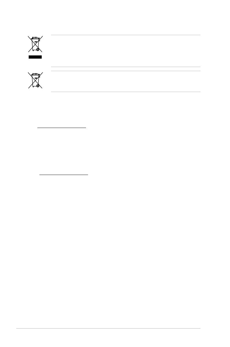
1.4 Front panel features
The front panel of the RS720-E7-RS24-EG features a simple yet stylish design. The twenty
four (24) 2.5-inch hot-swappable Serial ATA (SATA)/SAS HDD bays, two USB 2.0 ports, LEDs
and buttons are all located on the front of the server for easy access.
Refer to section 1.7.1 Front panel LEDs for the LED descriptions.
1
2
USB 2.0 ports
Thumbscrew 2.5-inch HDD Trays Thumbscrew
Front panel LEDs and buttons
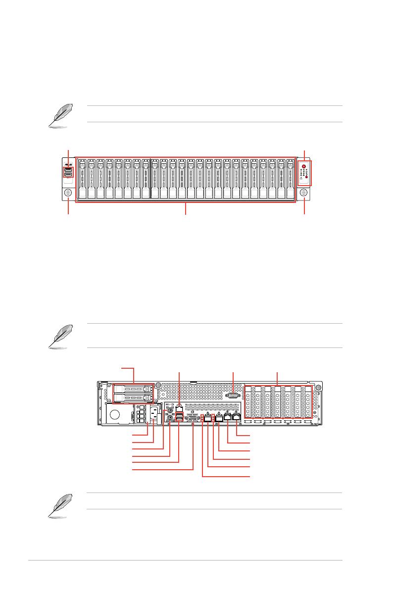
The rear panel of RS720-E7-RS24-EG includes two hot-swappable SSD trays, expansion
slots, I/O ports, SFP+ 10G ports, and system power sockets.
The ports for the USB, VGA, and Gigabit LANs do not appear on the rear panel if the
motherboard is not present.
*The LAN port 3 is for ASUS ASMB6-iKVM controller only.
1.5 Rear panel features
VGA port
SSD drive trays
Gigabit LAN port 1
Gigabit LAN port 2
USB 2.0 ports
PS/2 mouse port
Expansion slot cover
SFP+_2
SFP+_2 LEDs
SFP_1
SFP+_1 LEDs
PS/2 keyboard
Redundant Power Supply
LAN port 3* COM port
Power Socket

ASUS RS720-E7-RS24-EG 1-7
1.6 Internal features
The barebone server includes the basic components as shown.
1. Redundant Power supply
2. Z9PE-D16-10G/DUAL Server
Boards
3. Front System fans
4. SATA backplane (hidden)
5. HDD trays
(24 x 2.5-inch HDD trays)
6. Front I/O boards (hidden)
7. SSD drive bays
8. Asset Tag (hidden)
The barebone server does not include a oppy disk drive drive. Connect a USB oppy disk
drive to any of the USB ports on the front or rear panel if you need to use a oppy disk.
*WARNING
HAZARDOUS MOVING PARTS
KEEP FINGERS AND OTHER BODY PARTS AWAY
Turn off the system power and detach the power supply before removing or replacing any
system component.
12
3
7
85
3
6
3 3
4
Chapter 1: Product introduction
1-8
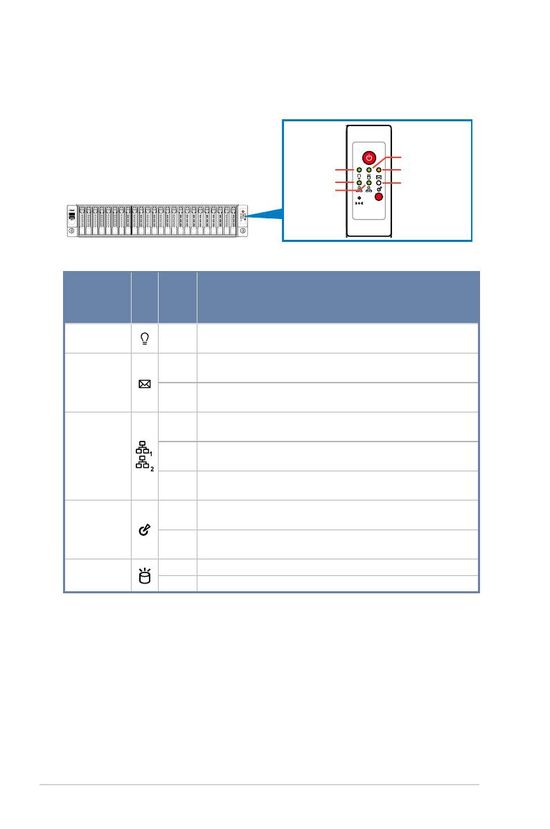
1.7 LED information
1.7.1 Front panel LEDs
LED Icon Display
status Description
Power LED ON System power ON
Message LED
OFF System is normal; no incoming event
ON A hardware monitor event is indicated
LAN LEDs
OFF No LAN connection
Blinking LAN is transmitting or receiving data
ON LAN connection is present
Location LED
ON Location switched is pressed
OFF Normal status. (Press the location switch again to turn off.)
HDD Access
LED
Green Data is being read/written into the HDD
OFF HDD failure or no HDD is installed
1
2
1
2
Message LED
LAN2 LED
LAN1 LED
HDD Access LED
Location LED
Power LED
/