
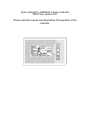
User’s manual for distillation column controller
“SKN” from version 2.07
Please read this manual carefully before first operation of the
controller.

Firma Bolecki Tel. 503-064-713 (8 – 21)
ul. Żwirki i Wigury 24 [email protected]
32-650 Kęty forum.bolecki.pl
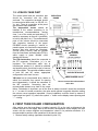
INFORMATION FOR THE CONSUMER
The symbol presented on products or in documentation enclosed with
them informs the non-operational electrical or electronic appliances
shall not be disposed together with municipal wastes. When disposal,
recycling of recovery of subassemblies is necessary, the right
proceeding is to give over the appliance to a specialized collection point,
where it will be taken over free of charge.
1. INSTALLATION RECOMENDATIONS.........................................................................1
1.1. HIGH-VOLTAGE PART...........................................................................................2
1.2. LOW-VOLTAGE PART............................................................................................3
2. FIRST TURN ON AND CONFIGURATION...................................................................4
3. SERVICE MENU...............................................................................................................4
3.1. SEMI-AUTOMATIC MODE.....................................................................................4
3.2. INPUT/OUTPUT TEST.............................................................................................5
3.3. RESET........................................................................................................................5
3.4. ADDITIONAL SETTINGS........................................................................................5
3.4.1 DISPLAY SETTINGS.........................................................................................6
3.4.2 OUTPUT SETTINGS..........................................................................................6
3.4.3 SENSORS SETTINGS........................................................................................8
4. PROCESS SETTINGS MENU.........................................................................................8
4.1. HEATING...................................................................................................................9
4.2. ENFORCED WATERING.........................................................................................9
4.3. COLUMN STABILIZATION....................................................................................9
4.4. HEADS COLLECTION.............................................................................................9
4.5. HEART COLLECTION.............................................................................................9
4.6. TAILS COLLECTION...............................................................................................9
4.7. PROCESS ENDING.................................................................................................10
5. THE APPLIANCE OPERATION...................................................................................10
6. MEMORY CARD...........................................................................................................10
6.1. OPERATION PARAMETERS REGISTER............................................................10
6.2. SOFTWARE UPDATE............................................................................................11

The SKN controller is designed to control the process in LM/VM distillation columns.
Functions of the controller make the column operation much easier. Main features of the
controller:
- Two independent outputs 16A 230/400V.
- Cooling water electrovalve (NO relay output)
- LM electrovalve (max 12V 1,5A NO/NC)
- VM motorized valve (max 12V 40mA)
- Four thermometers with resolution of 0.01
o
C, including one of two sensors, which
could control the VM valve
- Graphic display with high contrast
1. INSTALLATION RECOMENDATIONS
It is recommended to install the actuator in the area of heaters, in an enclosure protecting it
against accidental flooding (having in mind such cases like leaking water connections, etc.).
At the same time, the enclosure must provide free air flow that is necessary for cooling the
SSR relay controlling the heaters. The plate should be fixed to the enclosure with plastic
spacers provided in the kit. Using metal spacers may lead to a short-circuit, damage of the
appliance or even electric shock of the user.
The control panel should be installed in a
convenient place, having in mind there is
a slot for memory card at the top of the
panel – flooding the appliance from this
side for sure would cause the electronic to
be flooded. The panel is provided with its
dedicated bracket. Put the panel on the
bracket and then pull it down.
- Remember, the appliance is supplied
with a dangerous voltage. Its electrical
connection should be entrusted to a
person with suitable knowledge and
authorization. It is forbidden to use the
appliance when its enclosure or wiring
is damaged, also if there is only
suspicion of malfunction of the system.
- The appliance may activate its output
at any time without signaling this
event, even if does not result from its
operation cycle. It is forbidden to make
any manipulation on the electrical part
of the system when it is connected to
the mains. It applies also to the low-
voltage elements.
- Do not turn the appliance ON when
the heaters are not covered with liquid
– in case of unexpected turning ON
they could be damaged. It should be
considered to install additional
(mechanical) heaters switch.
- The SKN controller has incorporated
electronic relay (SSR) controlling the
heaters, however it does not ensure
reliable, mechanical heaters
disconnection. Moreover, in case of its
failure (overloading, short-circuit, etc.),
most likely it will supply the heaters
with full voltage.
- The supply connection should be
easily accessible. It must ensure quick
and trouble-free disconnection of the
system form the mains at any time.
- The wires and connectors used should
be suitable for the appliance power. It
is recommended to install appropriate
terminal box with appropriate breakers
and differential protection.
1

- Perform periodical maintenance of the
appliance. After first few cycles of
operation, check especially the
connections operating under
significant load, retightening might be
necessary.
- It is forbidden to use the system in
places that can catch fire from the
wires used, it is forbidden to store
flammable materials in the
neighborhood of the system operation.
-
- Metal elements of the appliance
must be grounded. Please keep in
mind the fluids are perfect
conductors, therefore each
element must be grounded even
though apparently it is isolated
(e.g. with hose) from the other
elements.
- It is forbidden to leave the system
connected to the mains without
supervision of a person with suitable
knowledge and skills.
Electronic supply voltage 230V AC +/-30%
Electronic power consumption Max 18W
Heaters supply voltage Max 400V AC
G1 & G2 output current Max 16A each
Water valve max current 1A
LM valve max current 1.5A
VM valve max current 40MA
Temp. measurement resolution 0.01
o
C
Temp. measurement accuracy +/-3
o
C (0 – 100
o
C range)
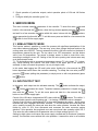
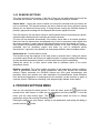
1.1. HIGH-VOLTAGE PART
The following diagrams show the examples of connection of this part of the appliance. The
mains voltage that is necessary for the electronics shall be connected to L N terminals,
paying attention the phase wire should be connected to “L”.
2

Water valve. The SKN controller is not designed to supply the water valve from its own
power supply. The water valve should be supplied from the mains 230V or separate power
supply. The ZW connector should be simply considered as a switch, which will close its
contacts when the controller wants to activate the water circulation. It enables to use only
NC valves.
The heaters, depending on their operation voltage, should be connected according to one of
the diagrams, considering GH1 and G2 outputs as the serial switches. If the heaters (or their
sections) are of different power, remember the power connected to the particular output – it
will be needed for further configuration of the appliance.
ATTENTION! The “grey” factory enclosure of the execution part ensures proper
cooling for current sup to 10A (for each G1 and G2). If the excepted current is to be
higher, it should be considered to place the execution part in different enclosure
providing adequately better ventilation.
3
FUSE
HEATRES
RELAY
230V
SUPPLY
WATER VALVE
RELAY
CONTROL PANEL
CONNECTOR
WATER
VALVE
max 2 x 3.6kW 230V
max 2 x 3.6kW 230V

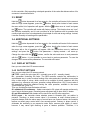
1.2. LOW-VOLTAGE PART
The control panel and the execution part
should be connected with the cable
enclosed. The respective terminals should
be connected at both ends (i.e. GD-GD, V+-
V+, etc.). There is a connector at the panel
that could be easily detached.
The temperature sensor should be
installed in the column according to its
manufacturer recommendations, leaving
circa 1 cm of the metal part protruding, if it
would be necessary to remove it (possibility
to hold it with pliers, etc.). The measurement
point of the column should be connected
with respective terminal of the panel.
DS18B20 circuits, operating in “normal” or
parasite power, are used as the temperature
sensors, the wire colors are important.
Ground (GND) is brown, Data line (viewed
from the connectors and label side) (DTA) is
white, supply is green. Mistake could
damage the sensor.
The LM electrovalve should be connected to
the EZ connector. Polarization (+/-) is not
important. The electrovalve cable, due to
interferences created in it, should be shielded
and possibly short, should not be put in harness
with other cables. The controller enables control
of both NO and NC valves, appropriate
configuration to be done in menu.
VM valve has an incorporated drive, thanks to
which, the controller may control its opening
rate independently. It should be connected to
the MZ connector. Connecting here not
recommended element may lead to the output
failure. Polarization is important, one of the wires is always red and it should be connected
to “+”. In case of inverted connection, the valve would operate in opposite direction making
the column correct operation impossible. Correct installation could be check by means of
input/output test (point 3.2), where the symbol “+” visible on the display means opening and
“-” – closing.
2. FIRST TURN ON AND CONFIGURATION
After making sure that everything is installed correctly, fill up the tank or disconnect the
heaters and turn on the supply. After a few seconds, the appliance should display the main
screen with the column diagram and temperature values in its particular elements. It is
recommended to perform a few operations in the service menu.
1. Restore factory settings (operation described in point 3.3).
4
EXECUTION
BOARD
KEG’S
SENSOR
BOTTOM
SENSOR
COLUMN
OR COOLER
SENSOR
TOP
SENSOR
LM ELECTRTOVALVE
VM MOTORIZED VALVE
Here to connect the red motorized
valve wire

2. Check operation of particular outputs, select operation points of VM and LM Valves
(3.2).
3. Configure initially the controller (point 3.4)
3. SERVICE MENU
This menu includes essential parameters of the controller. To enter this menu, press and
hold for e few seconds the button, when the logo screen appears press the button
and wait for e few seconds. Navigation within this menu is done with the buttons,
select appropriate function with . To exit this menu press and hold for e few seconds the
button or turn ON the supply again.
3.1. SEMI-AUTOMATIC MODE
This function makes it possible to control the process with significant participation of the
user without alarms signalization. The user may, at any time, change the power and turn the
cooling water valve ON/OFF. The only automatic function is VM valve control on the basis of
temperatures entered by the user. The top value is an OFF temperature, and the bottom
value is an ON temperature. Top sensor or bottom sensor is used to control this valve,
according to settings in menu 4.5. Setting of the VM valve opening rate is done same way
as in the automatic mode.
T1…T4 designations refer to successive temperature sensors (T1 is the head, T2 – bottom,
etc.). When entering this function, the clock visible in the upper part of the screen is
activated. It does not control the process, it is only to help the user.
In this mode, data logging into SD card is also active. Holding for a few seconds the
button depressed would cause the controller restarting. To accept the new valve position,
press the button (editing this parameter) or simply move to edit next parameter (press
the button).
3.2. INPUT/OUTPUT TEST
In this menu, each output can be activated manually. The button activates the output,
the button deactivates the output. Transition between parameters is looped and it is
done with the button. To exit this menu press and hold for e few seconds the
button or turn ON the supply again.
Control of the VM valve, designated as MZ is done with the buttons. The visible “+’
symbol should cause the valve opening and “-“ its closing, 0 means the valve is stopped.
Control of the LM valve, designated as EZ is done with changing the values – above some
threshold the valve “engages” and below “releases”. To find the optimal value controlling the
valve, carefully increase the value and note when the valve operates. Increase this value
further by circa 10...15%, then disconnect and reconnect the valve connector paying
attention if this operation has produced next and unequivocal vale operation within 30 s.
Then enter the value obtained as Dt parameter value in output settings (point 3.4.2).
Setting too high values could cause the power supply overload and its shut-down (controller
restart). If such effect occurs without the valve operation, it means this valve is not suitable
5

for this controller. Quite squealing or delayed operation of the valve after disconnection of its
connector is a natural behavior.
3.3. RESET
Hold the button depressed for a few seconds – the controller will restart. At the moment
when the logo screen appears, press the button, shortly after instead of main screen
the menu with a list of operations will appear. With the button move to “reset” and press
the button. The controller will restart with factory settings. This function does not “cure”
the controller wonderfully and it is not a solution for all the problems with its operation that
usually might arise from not understanding its principal of work and wrong settings. Instead,
it causes necessity of resetting all the parameters.
3.4. ADDITIONAL SETTINGS
Hold the button depressed for a few seconds – the controller will restart. At the moment
when the logo screen appears, press the button, shortly after instead of main screen
the menu with a list of operations will appear. With the button move to “additional
settings” and press the button, first parameters – display contrast – will come up.
Change the value with the buttons, confirm the value and move to next parameter
with the button. It is not possible to move back to previous parameter. To save the
changes move across all the parameters. The controller will restart.
3.4.1 DISPLAY SETTINGS
Here you can select the LCD screen contrast.
3.4.2 OUTPUT SETTINGS
Here you can select the LCD screen contrast.
LM TYPE – specify the valve type (NO – normally open or NC – normally closed)
Dt – parameter controlling the valve. The SKN controller controls the electrovalve in
sophisticated way, in order to reduce heating of the valve and make it possible to use valves
form a wide range of valves, which would not be suitable for direct operation with this
appliance (e.g. excessive coil power, operation voltage different then 12V). Correct value of
this parameter should be obtained testing the valve operation, available in the menu
“Input/Output test” (point 3.2).
Then you could define how the heaters will work.
G1 modulated, G2 continuous – Heater connected to G2 output will operate continuously,
even if set at minimum power. Essential power adjustment will be done with G1 heater.
G1 and G2 modulated. Both heaters will be turned On and Off at the same time.
G1/G1 power – the controller shows absolute power in kilowatts (kW), not relative in
percents. Therefore, to obtain correct value it is necessary to enter nominal power of
particular heaters. Both the above ways of control have one common feature, the controller
realizes so called group control with a few seconds period. Contrary to phase control, it
eliminates the necessity to use expensive noise filters, ensures good quality of control,
however it may cause light dimming in pace of heaters operation. Therefore, it is
6

recommended to work in mode of G1 modulated and G2 continuous, where the modulated
heater will be supplied form different phase then lighting.
Max VM opening – defines the maximum valve opening. When running the process it will
be impossible to select higher valve opening, reducing the possibility to select higher
capacity then the column can provide and frequent process destabilization at beginning
phase of collecting the heart.
Min VM opening – means minimum opening. When running the process it will be
impossible to select lower opening. Also the controller itself will no go below this vale if the
opening correction option is active. Use a value at which the rate of collection is still
reasonable. Setting too low value or even total closing would cause the controller to
encounter a problem with transferring to tails when the close time principle is selected, or
would case unnecessarily long collection of the heart and energy consumption.
7

8

3.4.3 SENSORS SETTINGS
This menu consists of two screens. In the first of them you can define what sensors will be
connected the controller, and therefore their correct operation should be checked.
Sensor alarm – leaving the sensor crossed out informs the controller that give sensor will
not be connected. The selected sensors are being checked only during process running
(before you can disconnect them freely). If during process running the controller detects a
problem, appropriate message will be displayed and acoustic signal will sound.
From this moment, the user has a minute to confirm/cancel the error by pressing any button,
otherwise after indicated time the controller will stop the process.
The error will be cancelled automatically if the sensor comes back to its normal operation.
Next error from the same sensor would appear only if even for a moment correct signal from
this sensor reappear, it means permanently defected sensor would be signaled only once.
Such method of proceeding ensures determined reaction to an error, however excludes
immediate and not necessary column shut down e.g. due to accidental sensor
disconnection. It gives the user possibility to make proper decision without needless stress.
Head sensor as – to select head or cooler.
This function brings also changes in the main screen or process menu. Setting the sensor
as a head sensor would add to menu an additional option of process ending after obtaining
at it the specified temperature (without it, still the other sensors will be selectable).
Setting the sensor as a cooler sensor would add an additional option of the cooler
temperature control.
Reading correction. This option enables correction of the temperature sensors readings.
Value in parenthesis shows an actual temperature taking into account the correction
entered. Please remember the DS18b20 sensors are quite good thermometers and
practically offers much smaller error then described in the specifications. Small difference
from the actual temperature is meaningless for the controller, so this correction is purely a
cosmetic function. Differences exceeding a few degrees might indicate sensor defect.
4. PROCESS SETTINGS MENU
Here you can configure the entire process. To enter this menu, press the button at the
moment when main screen is visible and no parameters are being changed. To exit this
menu, pres the same button again. The buttons rewind the menu or change
parameters values after entering the editing menu.
Entering the editing of a given screen, moving to next parameters, and exiting the editing is
possible with the button.
9

Turning Off and long holding of the button depressed when making changes would not
save them (saving into memory is done with exiting the editing).
Principles of the process might be also changed during its running. Remember, however,
such changes have immediate impact so unexpected process interruption or move to next
phase may happen. The entire distillation process runs according to subsequent, below
listed principles.
4.1. HEATING
First process stage. Here you can define the power of heating, at what temperature of the
column bottom the electrovalve of cooling water should be activated and what temperature
of the column top should start the watering stage.
4.2. ENFORCED WATERING
Consists of three attempts of watering with pauses the purpose of which is better wetting of
the column packing. This option is aimed at controlled filling of the column with water. When
not sure how to set up these parameters, it is recommended to set up much longer time
then excepted (even tens of minutes) and control the watering process with self-contained
changes of power form the main screen. And then enforce transition to a next stage
(described in point 5). Such method ensures comfortable work without a pressure of time
and necessity of restarting the process in case of its omitting.
4.3. COLUMN STABILIZATION
This principle determines the power and time of stabilization.
4.4. HEADS COLLECTION
Fourth stage. This principle defines the power effective from this moment and a time for
which the user can collect so called kindling and heads. During this stage the LM valve is
being open, and the VM valve is still closed.
4.5. HEART COLLECTION
Fifth stage. This principle defines how the main product will be collected, the user decides
what jump from the temperature of the day is to cause the end of collection. Which sensor
(column top or bottom) will control the VM valve. Beginning value of the VM valve opening
and a step decreasing each next valve opening. The temperature of the day is to be defined
automatically by the controller during its operation. From the moment of starting this stage,
the user may at any time, from the main screen, change the opening/closing temperature
and the current valve opening level. For the time of heart collection, the LM valve is being
closed.
4.6. TAILS COLLECTION
Sixth stage. The VM valve is being closed, the LM valve is being reopened. This stage can
be induced if the selected principle is met. You can select the type of sensor (keg, bottom or
top) and temperature value to be obtained at this sensor, or maximum time of the VM being
closed. In order to use the temperatures in particular column points, first it is recommended
to perform the column test and find out these values (spread of the sensor parameters, the
column operation conditions, etc.).
10

A better solution might be the principle of VM closing time. When the column is good (and
the accessories set correctly), the valve will start to close in the very ending phase of
collection and each next closing will be longer and longer. The so far observations indicate
the time of a level of 10 min. should be enough.
4.7. PROCESS ENDING
With proper parameters setting, in this principle the controller may end the process directly
from the heart collection (skipping the tails). The user defines how long the cooling shall be
active after the heaters are turned off, and how to detect the end of process. It could be in
result of exceeding the temperature in the KEG or the column bottom or top.
5. THE APPLIANCE OPERATION
The main screen with the column view enables a few functions such as beginning and end
of process, transition to next stage or modification of parameters during operation. Enter the
functions selection by pressing the button. When the process is stopped, it is possible
only to restart the process (pressing the button). During process running you can move
to a next stage, quickly change the VM valve temperature, change the power currently used
or end the entire process. In case of changing the valve opening rate, after changing the
value press the button, or simply move to another parameter pressing the button
(changing the valve opening is effective only when the valve is opened). The second screen
displays information on the VM valve operation, it means the current or previous times the
valve was closed. This information enables to make a decision on the possible settings
corrections, ending the process or to be familiar with the process status in general. Here you
can also see the temperature of the cooler located in the execution part. Navigation between
these screen is possible by pressing the buttons.
It is possible to enter the menu and change the process principles during process running,
however remember the modification of the current stage may cause its unexpected ending
and transition to a subsequent stage.
6. MEMORY CARD
The appliance makes it possible to record the significant operation parameters into memory
card, or to updates the controller software quickly.
Only SD/MicroSD cards of up to 32GB can be used with this appliance. There is no
guarantee the appliance will function correctly with all types of cards meeting these
requirements.
6.1. OPERATION PARAMETERS REGISTER
Each start of process in automatic or semiautomatic mode causes the controller to generate
a new .csv file, where the data will be regularly registered. Active registering into the card is
being signaled with regular flashing of the SD icon in the front of the controller. Such a file
could be imported into calculation sheet. Each next file has an ascending number in its
name, the file creation date is random. It is forbidden to move or remove the card from the
appliance when the process is started. It could cause the file to be damaged or the process
to be interrupted.
11

6.2. SOFTWARE UPDATE
Updating process is simple, however the appliance not covered with warranty could be
damaged. Each update attempt is recorded in the controller together with a file fragment. Do
not load a software other then designed for this appliance. During updating is could happen
the controller will cease its correct operation and e.g. activate its outputs (a risk of heaters
damage, etc.)
It is natural that after updating the controller will signal an error of the settings
recorded in the memory. Even if the controller does not display such message, reset
it to factory settings.
Updating shall be always done in the following sequence:
- Save the file with a software to be loaded into the controller into the card.
- Check and possible modify the file name to S_SKN (or S_SKN.hex if your system shows
file extensions).
- Insert the card into the controller with the supply turned off.
- Turn the controller on with the button depressed.
The SD icon will flash a few times, then during a few seconds it will flash quickly, then
slowly. If the update is successful, the controller will start up automatically with the new
software. If instead, the SD icon will flash regularly it means update failure. Number of
flashes informs the cause of failure:
2 flashes: problem with the card, try to format it or use another card
3 flashes: the expected file not detected
4-6 flashes: problem with the file content (e.g. damaged)
If there is any problem with the memory card, first operation should be its formatting for
FAT32 file system. Correct updating process (software uploading) takes about 10 seconds.
The appliance does not react to supply application, the panel does not light, the fan
does not rotate.
Check the supply connections, check the fuse.
The appliance does not react to supply application, the panel does not light, the fan
rotates.
Check correct connection of the low- and high-voltage parts, disconnect the electrovalve
and the temperature sensors.
One of the heaters works, its control lamp on the execution panel does not light.
If the connection is correct (the output used to work), the most likely the output is damaged
due to short-circuit.
12

One of the heaters works, its control
lamp on the execution panel does not
light.
Check the connection between the low-
and high-voltage parts.
One of the heaters works, its control
lamp on the execution panel lights.
Check the heater connection and its
efficiency.
The panel resets at the moment of LM
valve operation, or it does it in cycles
trying to turn on.
Disconnect the VM valve, it is an
excessive load for the controller. Check
the VM valve for the possible short-circuit,
check the valve type (NO/NC),
check/reduce the Dt parameter.
The controller displays a memory error.
Such situation can happen after software
updating or sporadically due to
disturbances (e.g. shut-down during
settings modifications).
One of the heaters work when it should
not, its control lamp on the execution
panel lights.
Check the connection between the low-
and high-voltage parts.
One of the heaters does not work, its
control lamp on the execution panel
lights.
Check the connection between the low-
and high-voltage parts.
One of the heaters does not work, its
control lamp on the execution panel
lights.
Check the connection between the low-
and high-voltage parts.
Immediately after process start, there
is an error of cooler overheating.
Sensor on the execution panel damaged
(service is necessary) or incorrect
connection between the low- and high-
voltage parts.
Cooler overheating error appears some
time after the process start.
Cooling of the execution part is ineffective,
ventilation holes are obstructed, the
execution part heats up from the tank, the
heaters connected are of excessive
power.
The controller displays error for a
sensor that is not connected.
Configure correctly the sensors used.
The panel resets at the moment of LM
valve operation, or it does it in cycles
trying to turn on.
Disconnect the VM valve, it is an
excessive load for the controller. Check
the VM valve for the possible short-circuit,
check the valve type (NO/NC),
check/reduce the Dt parameter.
The controller displays a memory error.
Such situation can happen after software
updating or sporadically due to
disturbances (e.g. shut-down during
settings modifications).
If the above suggestions do not solve the problem, contact the manufacturer.
13

Serial number ……………………
Date of sale and stamp
WARRANTY CARD
- The manufacturer warrants correct operation of the appliance for a period of 24 months
from the date of sale.
- Factory defects revealed within the above period will be eliminated free-of-charge within
14 working days from the date of receiving it to the service. Before sending the
appliance back, contact the manufacturer.
- Return the appliance cleaned directly to the manufacturer (it will significantly shorten the
repair time) at your cost, in a package ensuring its proper protection, enclosing the proof
of purchase and the warranty card correctly filled in. Enclose also contact data of the
claiming person (shipping address, telephone number) and precise failure description.
- Warranty is void if the seal or the label with serial number is not intact.
- Warranty does not cover failures not resulting from the manufacturer errors, e.g. not
approved design modification, improper installation or use, overloads, atmospheric
discharges, mains overvoltages, fouling or flooding, mechanical damages.
- Warranty card that is illegible, not fully filled out, or with traces of unauthorized
corrections is invalid!
- This warranty card doe not exclude nor limit the consumer rights resulting from the
regulations of the laws.
14
-
 1
1
-
 2
2
-
 3
3
-
 4
4
-
 5
5
-
 6
6
-
 7
7
-
 8
8
-
 9
9
-
 10
10
-
 11
11
-
 12
12
-
 13
13
-
 14
14
-
 15
15
-
 16
16


Ask a question and I''ll find the answer in the document
Finding information in a document is now easier with AI
Other documents
-
Saeco MINUTO User manual
-
Bradford White RTG-K-160-N1 User manual
-
Emerson E2 User manual
-
Bosch 125FX LP User manual
-
American Dryer Corp. GWH 425 EF User manual
-
Bosch Appliances GWH 425 EF User manual
-
Teledyne API T753U User manual
-
Comelit simplehome Technical Manual
-
 Teledyne 4060 User manual
-
