
The World in Communication
®
Prodotto o importato da:
CTE INTERNATIONAL s.r.l.
Via. R.Sevardi 7- 42010 Mancasale
Reggio Emilia Italia
L’uso di questo apparato può essere
soggetto a restrizioni nazionali.
Prima dell'uso leggere attentamente le
istruzioni. Se il prodotto contiene batterie:
non gettare nel fuoco, non disperdere
nell’ambiente dopo l’uso, usare gli appositi
contenitori per la raccolta.
Produced or imported by:
CTE INTERNATIONAL s.r.l.
Via. R.Sevardi 7 - 42010 Mancasale
Reggio Emilia Italy
ALAN UK
Unit 2, Callenders, Paddington Drive,
Churchward Park, Swindon, Wiltshire, SN5
7YW United Kingdom
The use of this transceiver can be subject
to national restrictions. Read the
instructions carefully before installation
and use. If the product contains dry cells
or rechargeable batteries do not throw the
batteries into the fire. To disperse after
use, throw into the appropriate containers.
Producido o importado por:
ALAN COMMUNICATIONS, S.A.
C/Cobalto, 48 - 08940 Cornellà De
Llobregat - España Tel 902 38 48 78
El uso de este equipo está sujeto a la
obtención de la correspondiente
autorización administrativa. Antes de
utilizar, lea atentamente el manual de uso.
Si el producto contiene pilas o baterias:
no las tire al fuego ni las disperse en el
ambiente después de su uso, utilice los
contenedores especiales para su recogida.
Herstellung/Vertrieb durch:
ALAN ELECTRONICS GmbH
Daimlerstraße 1K
D-63303 Dreieich Deutschland
Die Benutzung dieses Handfunkgerätes
ist von den landesspezifischen
Bestimmungen abhängig.
Vor Benutzung Bedienungsanleitung
beachten. Bei Verwendung von Batterien
beachten Sie bitte die
Umweltbestimmungen. Batterien niemals
ins offene Feuer werfen und nur in den
dafür vorgesehenen Sammelbehälter
entsorgen.
D
The World in Communication
Alan
HP 106
(VHF)
Alan
HP 406
(UHF)
Manuale d'uso
User's manual
Manuel d’utilisation
Bedienungsanleitung
Manual del usuario
Manuale do utilizador
I
GB
P
F
E

5
6
12
34
11
12
7
8
10 9
Diritto d'autore 2003 della CTE International Italia; tutti i diritti riservati.
Copyright 2003 by CTE International Italy; all rights reserved.
Les droits d’auteur © 2003 par CTE International Italie; tous droits réservés.
Copyright 2003 by CTE International Italy; alle Rechte vorbehalten.
Derechos del autor 2003 de CTE International Italia; todos los derechos reservados.
Direito de autor 2003 de CTE International Italia; todos os direitos são reservados.

English
ISTR106_int 26-09-2003 9:47 Pagina 23

In this book... 1
1ALAN HP106/HP406 – THE POWER OF SIMPLICITY 3
2SAFETY FIRST 4
2.1 Conventions and Symbols in this Book 4
2.2 Warning notes 4
2.3 Safety 5
3PART NAMES AND THEIR FUNCTIONS 6
3.1 Top 6
3.2 Front 7
3.3 Side (left and right) 7
4SETUP 8
4.1 Unpacking 8
4.2 Fitting/removing the antenna 8
4.3 Installing/removing the battery pack 9
4.4 Installing/removing the belt clip 9
4.5 Charging the battery pack 10
5BASIC OPERATIONS 10
5.1 Switching the radio ON/OFF 10
5.2 Adjusting volume 11
5.3 Channel selection 11
5.4 Reception 11
5.5 Monitor 12
5.6 Transmission 12
5.6.a Time-out Transmission Timer (TOT) 12
5.6.b Busy Channel Lock Out 13
5.6.c Transmission Power 13
6CTCSS/DCS AND SELECTIVE CALL OPERATION 14
6.1 Reception 14
6.2 Transmission 14
6.2.a CTCSS/DCS transmission 14
6.2.b Sending a normal selective call 14
6.2.c Sending an emergency selective call 14
7ADVANCED OPERATIONS 15
7.1 Channel Scanning 15
7.1.a Enabling/disabling scanning 15
7.1.b Priority Channel 15
7.2 Handsfree transmission (VOX) 16
7.2.a Headset Connection 16
7.2.b Enabling/disabling VOX 16
7.2.c Adjusting VOX sensitivity 16
7.3 Confidential Communications (scrambler) 16
8CARE AND MAINTENANCE 17
8.1 Battery Packs 17
8.1.a Properly charging battery packs 17
8.1.b Memory effect 18
8.1.c Erasing memory effect 18
8.1.d Warnings for battery and chargers use 18
8.2 Radio maintenance 19
8.2.a Cleaning the radio 19
8.2.b Cleaning battery packs 19
8.2.c Connectors 19
English
ISTR106_int 26-09-2003 9:47 Pagina 1

2In this book
9OPTIONAL ACCESSORIES 20
9.1 Microphone/speaker or Headset with microphone 20
9.1.a Contacts layout 20
9.1.b Connection 20
10 QUICK REFERENCE 21
10.1 Operation resume 21
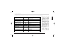
11 TECHNICAL SPECIFICATIONS 22
11.1 Test methods 22
11.2 Specifications table 22
English
ISTR106_int 26-09-2003 9:47 Pagina 2

ALAN HP106/HP406 - The power of semplicity 3
1 ALAN HP106/HP 406 – The power of semplicity
Congratulations. ALAN HP106/HP406 is a Professional Radio, whose
rugged design allows it to be your reliable partner even during hard wor-
king days.
It’s a transceiver designed to be easy to use, but featured with advanced
functions that make it flexible to every use.
We state the most important ones:
• Easy to use – just only five commands to control all the transceiver’s
functions.
• Channel scanning – it allows to automatically search the radio
signals on the programmed channels.
• VOX (Voice Operated eXchange) – it allows to enable the transmis-
sion by simply speaking, in full handsfree condition, by the optional
headset/microphone.
• CTCSS/DCS – to share more radio networks on the same frequency
and safely access to your radio repeaters.
• Selective call – for more advanced radio network management. You
can individually call a user inside a network or make group calls.
• Emergency selective call – you can send it, when needed, with a
simple command protected against accidental switching.
• Analogue scrambler – for confidential communications. Radio com-
munications are encoded and decoded from every ALAN HP106 in
order to reduce the risk of tapping from third parties who are watching
your frequency.
• Wide range of optional accessories which allow to extend the flexi-
bility of use.
Transceiver’s specifications of ALAN HP106/HP4065 are compliant
with ETS 300 086, moreover its top level design and resistance are
compliant with IEC529 level IP54 and MIL STD 810 C,D,E.
CTE International is committed to continuous quality improve, for this
reason specifications may vary without prior notice.
English
ISTR106_int 26-09-2003 9:47 Pagina 3

4Safety first
2 Safety first
2.1 Conventions and Symbols in this Book
This symbol marks a ‘note’. Notes are hints or tips which offer addi-
tional information to allow an easier use of the device and obtain the
best performances.
This symbol marks a ‘caution’. Cautions are special notices
which you should read and follow carefully to avoid possible
damage to your equipment and to avoid potential danger to
yourself or other people.
Key names will be highlighted in bold.
Important sentences and words are highlighted in Italic.
2.2 Warning notes
Every effort has been made to ensure that the information in this
document is complete, accurate and up-to-date. CTE
International assumes no responsibility for the results of errors
beyond its control. The manufacturer of this equipment also can-
not guarantee that changes in the equipment made by non
authorized people will not affect the applicability of the informa-
tion in it.
The operations described in this manual should be executed fol-
lowing the order they are listed. The consultation references of
the chapters/paragraphs are exclusively listed to allow a more
practical use.
The reliability of what is described in this manual is intended
errors and omissions expected. In case of any doubts please
contact your dealer/radio network manager.
English
ISTR106_int 26-09-2003 9:47 Pagina 4

Safety first 5
2.3 Safety
Your ALAN HP106/HP406 handheld transceiver has been carefully desi-
gned to give you years of safe, reliable performance. As with all electrical
equipments, however, there are a few basic precautions you should take
to avoid hurting yourself or damaging the radio:
Read the instructions in this handbook carefully. Be sure to save
it for future reference.
Read and follow all the warning labels and instruction on the
radio itself and on the accessories.
Don’t carry the transceiver by the antenna. This may damage the
antenna or antenna terminal. Grasp it by its base (not the tip!)
when you need to place or remove it.
Don’t keep the radio with the antenna very close to you, or tou-
ching exposed parts of the body, while transmitting. The radio
will perform best if the microphone is 5-10 cm away from the
mouth and the radio is vertical.
Be sure the PTT key is not accidentally depressed when you
don’t need to transmit.
Do not operate the radio near unshielded electrical blasting caps
or in an explosive atmosphere.
Don’t transmit without the antenna fitted on the radio or with a
damaged antenna. Though it is provided with a protection, it may
seriously damage the TX output final stage.
Respect the environment conditions. The radio is designed to be
used in heavy environments, however avoid exposing it to extre-
mely hot or cold temperature (out of the range between –30° to
+60°C). Don’t expose the transceiver to excessive vibrations as
well as dusty or rainy places.
Never try to disassemble or service the radio by yourself (aside
from the routine maintenance described in this handbook). It will
immediately void the warranty and you may cause damage
requiring extensive repair work. Always contact your local dealer
for assistance.
Grasp your radios firmly. Otherwise it may fall and be damaged.
Use only genuine accessories. Non original ones could seriously
damage your handheld transceiver.
Do not use your radio near water or spill liquid of any kind into it.
If the transceiver gets wet immediately, dry it by a soft and clean
cloth.
Switch the radio off before you clean it. Strictly follow the direc-
tions stated in Chapter 8.
Handle the battery properly. Strictly follow the directions stated
in Chapter 8.
Be certain that your power source matches the rating listed for
the supplied battery charger. If you are not sure, check with your
dealer or with your local power company.
To avoid damaging the power cable of the battery charger, do
not put anything on it or place it where it will be walked on.
This product complies with the requirements of the Council Directives
89/336/EEC and 73/23/EEC on the approximation of the laws of the
member states relating to electromagnetic compatibility and low voltage.
English
ISTR106_int 26-09-2003 9:47 Pagina 5

6Part names and their functions
3 Part names and their functions
We recommend to have a look to this section in order to familiarize with
the transceiver’s main parts and controls. Numbers in brackets refer to
the images.
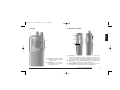
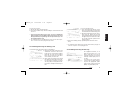
3.1 Top
[1] Antenna connector (MX thread type). Fit the supplied rubber
antenna to this connector.
[2] Power ON/OFF knob. Rotate this knob to turn the transceiver on
and off and to adjust the monitor volume level.
[3] Channel selector knob. Rotate this knob to select the operative
channel. It also defines the scanning priority channel.
[4] Status LED. Glows in different colors to show the current radio’s
status.
English
1
34
2
ISTR106_int 26-09-2003 9:47 Pagina 6

Part names and their functions 7
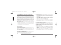
3.2 Front
[5] Speaker. The built in speaker
located in this point emits the
reception sound.
[6] Microphone. Your voice is
detected by the microphone
located in this place.
3.3 Side (left and right)
[7] Accessory connector (under the cover cap). To connect the exter-
nal speaker / microphone, headsets for VOX use and other acces-
sories. It must be protected with the supplied plastic cap when not
in use. For the related connections please refer to the Chapter 9.1.
[8] Battery pack. The rechargeable NiMH battery pack supplies energy
to your radio. For details please see the paragraph 4.5.
[9] Release button (located on the battery’s body). Allows to remove
the battery pack. For details please see the paragraph 4.3.
English
5
6
10
11
12
9
7
8
ISTR106_int 26-09-2003 9:47 Pagina 7

8Setup
[10] MON (monitor) button. This button carries out different functions.
The main ones are the following:
• If you briefly press it, you will enable/disable the audio monito-
ring of the radio traffic on the selected channel (if enabled). For
details please see the paragraph 5.5.
• If you keep it pressed, the selective call #1 (if enabled) will be
sent. For details please see the paragraph 6.2.b
[11] PTT (Push To Talk) button. When pressed, it switches the trans-
ceiver from reception to transmission. For details please see the
paragraph 5.6.
[12] FUNC (Function) button. This button carries out different functions.
The main ones are the following:
• If you briefly press it, you can adjust the VOX sensitivity by swit-
ching one of two available levels. For details please see the para-
graph 7.2.c
• If you keep it pressed, the selective call #2 (if enabled) will be
sent. For details please see the paragraph 6.2.b
4 Setup
4.1 Unpacking
The following items are in the package:
(a) Transceiver’s main body
(b) Rubber ducky antenna
(c) Battery pack NiMH 1,300 mA/H
(d) Belt clip
(e) User’s guide (this book!)
If something is missing please promptly advise your supplier.
The battery charger is available as option in two versions. For details
please see the paragraph 4.5.
4.2 Fitting/removing the antenna
To fit the antenna:
1) Hold the transceiver directing its antenna connector to the top with
one hand and the base (the thicker part with the MX threaded con-
nector) of the rubber ducky antenna with the other one.
2) Direct the base of the antenna to the transceiver’s antenna connector.
3) Screw down the antenna to the antenna connector rotating it clock-
wise until it firmly locks.
Do not overtight the antenna in order to avoid the damage of the
transceiver’s threaded connector or the antenna connector.
English
ISTR106_int 26-09-2003 9:47 Pagina 8

Setup 9
To remove the antenna:
1) Execute the above-mentioned step 1.
2) Unscrew the rubber ducky antenna rotating it counterclockwise and
remove it.
Leave the antenna fitted on the radio. You can’t communicate
without it. Moreover, transmitting without the antenna (or with a
damaged antenna) may damage the TX output final stage. Use
the supplied antenna only.
The supplied antenna is broadband type and covers the whole spec-
trum, so it doesn’t need any alignment procedure.
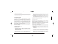
4.3 Installing/removing the battery pack
To install the battery pack (please refer to the drawing):
1) Direct the front part of the transceiver
downwards. Hold the transceiver’s
body with one hand and the battery
pack with the other. Put the battery
pack onto the lower part of the trans-
ceiver’s battery slot as shown.
2) Firmly push the battery pack toward
the upper part of the transceiver’s bat-
tery slot until you will hear a mechani-
cal snap (click), meaning that the bat-
tery pack is steadily locked in its posi-
tion.
To remove the battery pack:
1) Press and hold in the direction shown
by the arrow the battery release button
located in the back of the battery pack.
2) Ensure that the battery pack is unloc-
ked, keep the button pressed and
gently pull the battery pack away from
the upper edge of the transceiver’s bat-
tery slot (the opposite operation of the
previous step 2).
3) Remove the battery pack by separating it from the transceiver’s
body.
For details about the battery pack charge and the battery chargers to
make use of please see the paragraph 4.5.
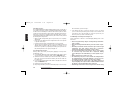
4.4 Installing/removing the belt clip
The supplied belt allows you to
hang the transceiver up to your
belt or jacket when you are not
using the radio and you are just in
stand-by condition (ready to recei-
ve calls).
To fit the belt clip onto the trans-
ceiver’s body just gently slide the
clip into the appropriate guides
located in the transceiver’s back
(battery slot) until it firmly locks.
English
1slide down
2push down
1push down
2let up
1slide down
3slide over
2press
ISTR106_int 26-09-2003 9:47 Pagina 9

10 Basic operations
To remove the belt press the belt clip spring and do the reverse of what
stated to fit the belt clip.
4.5 Charging the battery pack
In order to carry out the first charge of the battery pack please refer to the
User’s Manual supplied with the battery charger. This one is supplied
separately, as it is available in two versions to choose depending on your
needs:
• Desktop slow battery charger – more convenient model which
allows you to maximize the life of your battery pack.
• Rapid intelligent battery charger – for a quick and automatic bat-
tery charge.
For the next charges, best duty and battery life, please refer to
the paragraph 8.1.
The battery chargers are for indoor use only.
If the battery pack is new, it is not 100% efficient, meaning that it could
get discharged before the expected time. In order to reach the full
capacity, you must carry out the “running-in period” of the battery
pack through at least 3-4 complete charge/discharge cycles, after that
the battery reaches its maximum efficiency. For further details please
refer to the paragraph 8.1.a.
5 Basic operations
This section describes how the standard functions work. The standard
functions could have been modified by your radio network manager. For
such reason the way your transceiver operates can slightly differ from
what is described here.
IMPORTANT: In case of doubts please contact your dealer/radio net-
work manager for further details.
5.1 Switching the radio ON/OFF
To switch the radio on rotate the PWR/VOL knob clockwise beyond the
mechanical “click” until the radio is switched on: the internal CPU will
start an autotest as follows:
• The status LED will light green, then red and finally off.
• A multi-tone acoustic signal confirms that the autotest has been pas-
sed.
The self-test goes very fast, therefore the LED optical signaling could
not be seen.
To sw itch the radio off just completely rotate the PWR/VOL knob coun-
terclockwise beyond the mechanical “click” until the radio is switched off.
English
ISTR106_int 26-09-2003 9:47 Pagina 10

Basic operations 11
5.2 Adjusting volume
With the device turned on, rotate the PWR/VOL knob clockwise to
increase the volume or counterclockwise to reduce it. For a normal use
we suggest to keep it to the middle position.
5.3 Channel selection
If your radio has been programmed with more than one channel you can
easily change it. To select a channel, turn the channel selector knob
clockwise or counterclockwise until the channel indicator on the knob
matches the wished channel.
If the selected channel has not previously been programmed, the green
status LED remains permanently lit and a low error tone is produced.
5.4 Reception
Your radio could have been previously programmed to work, channel by
channel, in different modes: Open traffic, CTCSS/DCS or Selective
Call. Please have a look to each description and ask your radio network
manager or dealer which mode your radio channels have been program-
med.
• OPEN TRAFFIC - in this mode you will hear any communication
which will be transmitted on the selected channel. When no signals
are received, the circuit called Squelch will mute the audio of your
device in order to not let you hear the annoying background noise.
When the signals are received, the squelch will open (i.e. it will auto-
matically disabled), the status LED will glow green and you will hear
the message from the speaker. At the end of message the squelch will
shut automatically.
• CTCSS/DCS (Continuous Tone Code Squelch System - Digital
Coded Squelch) - they are systems which use particular TX signaling
(a continuous sub-audio tone for CTCSS or a digital sub-audio code
for DCS, both transmitted below the audio band, so not audible) as
an access “key” to work a repeater or to unlock the party’s squelch,
which is sensitive to this signaling only. This last condition allows to
share more radio networks on the same frequency. In this case you
will receive only messages coming from parties sending a proper TX
signaling, i.e. belonging to your group. During CTCSS/DCS operation,
only the reception of the appropriate CTCSS/DCS tone/code enables
the speaker, glowing amber the status LED. Eventual signals without
the appropriate CTCSS/DCS tone will leave the speaker muted and
will glow green the status LED. For further details please refer to the
chapter 6.
• SELECTIVE CALL: It is a signalling system which uses audio tones
in sequence (usually “5 tones” selective calls) to call a specific station
or group(s). In this case you will only receive calls that have your
selective call identification code (a number) or calls sent to the group
you belong. For further details please refer to the chapter 6.
CTCSS/DCS and Selective Call can be combined together.
CTCSS/DCS and Selective Call allow to share the same frequency
among more than one radio network, however they are just useful
to avoid disturbing stations not owning of the same network with
messages not related to them. In any case, if more than one sta-
tion is transmitting at the same time on the same channel, this will
cause interferences. Don’t transmit if the status LED is glowing
green or amber. Wait till nobody is transmitting on the channel.
English
ISTR106_int 26-09-2003 9:47 Pagina 11

12 Basic operations
5.5 Monitor
The MON (monitor) button is mainly useful for two purposes:
•If the channel you have tuned has been programmed in the Open
Traffic mode, briefly pressing the MON button temporarily disables
the squelch in order to allow you the reception of extremely weak
signals that can’t steadily open the squelch and are therefore recei-
ved “chopped”.
• If the channel you have tuned has been programmed with
CTCSS/DCS and/or Selective Call, a brief pressure of the MON but-
ton temporarily disables the CTCSS/DCS and/or Selective Call to
allow you to monitor all the communications on the tuned channel,
even the ones that are not belonging to your network. Practically, you
are able to temporarily receive in Open Traffic just briefly pressing the
MON button.
In any case, if the MON button is enabled on your transceiver, press
it briefly to temporarily monitor the signals on the tuned channel and
repeat this operation to return to the normal condition.
Every time the MON button is pressed, a high or low acoustic tone will
be produced to notify respectively the monitor function enabled (open
squelch or disabled CSCSS/selective call) or disabled (closed squelch
or enabled CSCSS/selective call)
Depending on the programming, the MON button could not be acti-
ve or work in order to disable the CTCSS/DCS only or the selective
call only. Please refer to your dealer/radio network manager for details.
5.6 Transmission
To transmit please follow this procedure:
1) Ensure that the channel is not busy (otherwise you will create an inter-
ference), verifying that the status LED is not glowing green or amber.
If the channel is not free, please wait until that condition (LED turned
off)
2) Keep pressed the PTT button and verify that the status LED is glo-
wing red to show that you are transmitting.
3) Speak with a normal voice level at approximately 5-10 cm from the
microphone.
4) When your message is over, release the PTT button ensuring that the
status LED is turned off.
Don’t shout! It won’t increase the distance range, but rather will make
you heard distorted.
Don’t release the PTT button before your message is over or start tal-
king before pressing it, otherwise your message will be “chopped”.”
A handheld radio doesn’t normally allow to talk and receive simulta-
neously, for this reason make your messages with a reasonable time.
When you are talking, the other parties can’t do that, so don’t occupy
too much the channel.
In order to transmit properly, please also see the following paragraphs.
5.6.a Time-out Transmission Timer (TOT)
The radio might be programmed with the internal TOT timer (Time Out
Timer) which automatically put your radio in reception if you talk too long
(after a preset time). In this case release the PTT button and wait for few
seconds: the radio TX features will be automatically restored. Ask the
network responsible or your dealer for further details.
English
ISTR106_int 26-09-2003 9:47 Pagina 12

Basic operations 13
5.6.b Busy Channel Lock Out
The radio might be programmed with the Busy Channel Lock Out
(BCLO). In this condition the PTT button is disabled during the reception
of radio signals. For such reason, if you are not able to transmit while you
are pressing the PTT button (the status LED is not glowing red), release
the PTT button and verify if the channel is actually free (the status LED is
turned off).
Depending on the programming, the BCLO can work either when it
finds any signal or in case of a signal with a specific CTCSS/DCS
signaling.
5.6.c Transmission Power
Your ALAN HP106/HP406 can transmit with two power levels according
to the distance of your party station(s). The low/high power channels are
preset during the programming and cannot be modified by the user. We
strongly recommend to use low power when possible: you will extend the
life of the battery and you will reduce the risk of interference with stations
not belonging to your radio network which could share with you the same
channel.
In case of low battery level, the unit will then automatically revert to
low power in order to help to extend the battery's operational life. In
this case, two short beeps (acoustic signals) will be heard before
transmission and one during reception.
English
ISTR106_int 26-09-2003 9:47 Pagina 13

14 CTCSS/DCS and Selective Call operation
6 CTCSS/DCS and Selective Call operation
6.1 Reception
The radio may be set-up so that, during the operation with the
CTCSS/DCS and/or Selective Call, audio is enabled only when you recei-
ve the appropriate CTCSS/DCS tone and/or Selective Call. Speaker will
then remain muted until the correct CTCSS tone, the correct DCS code
and/or the appropriate selective call is received. As soon as this condi-
tion takes place, the speaker will be unmuted allowing you to hear the
message and the status LED will glow amber. In case of reception of
signals without the correct tone, the speaker will remain muted and the
status LED will glow green.
Depending on the programming, you can temporarily disable the
CTCSS/DCS and the selective call in order to monitor the radio traf-
fic. For details please refer to the paragraph 5.5.
6.2 Transmission
6.2.a CTCSS/DCS transmission
If your transceiver has been programmed to transmit a CTCSS tone or a
DCS code, it is not necessary to do anything. The CTCSS tone or the
DCS code is automatically sent every time you transmit (the device does
not show this condition).
6.2.b Sending a normal selective call
On your transceiver the MON and FUNC buttons could have been pro-
grammed to send, respectively, the selective call Nr.1 and Nr.2.
To send a selective call:
1) Ensure that the channel is not busy (otherwise you will cause an inter-
ference), verifying that the status LED is not glowing green or amber.
If the channel is not free, please wait until that condition takes place
(LED turned-off)
2) Keep the MON or FUNC button pressed until the device will produce
a beep (about 3 seconds), then release the button. The default
address of every button is automatically recalled.
During a call, the transceiver turns automatically on the transmission
(the status LED glows red), so it is not necessary to press the PTT but-
ton.
6.2.c Sending an emergency selective call
If your transceiver has been programmed to send an emergency selecti-
ve call, you can send it by simultaneously pressing for a long time both
the MON and FUNC buttons until you will hear a beep and the status
LED will glow red, then release the buttons. The transceiver will send the
emergency selective call.
Please use the emergency selective call only if a real condition
requires its use. Please agree its use with your radio network
manager.
During a call the transceiver turns automatically on the transmission
(the status LED glows red), so it is not necessary to press the PTT but-
ton
English
ISTR106_int 26-09-2003 9:47 Pagina 14

Advanced operations 15
7 Advanced operations
In this section we’ll describe some advanced operations which you can
do with your handheld transceiver.
7.1 Channel Scanning
If you have more than one channel programmed, your ALAN
HP106/HP406 can scan them; in other words it can repeatedly switch
through all the programmed channels cyclically and automatically stop
when a signal is detected on one of them. During the scanning, only the
channels belonging to a specific scanning list (defined by the set-up) are
monitored. If a valid signal is received during the scanning, the scanning
stops and the communication is audible through the speaker. When the
signal is over, the scanning automatically restarts.
If the CTCSS/DCS or the selective call have been previously program-
med, the device could be set-up to stop only if the received signals con-
tain the correct signaling.
7.1.a Enabling/disabling scanning
To enable the scanning:
1) Turn off the device
2) Turn on the device keeping the MON + FUNC button pressed. A high
beep (after the acoustic tone of power-on confirmation stated in the
paragraph 5.1) notifies that the scanning is activated, and the status
LED will slowly blink amber.
During scanning the channel selector knob becomes invalid.
If the Scan List is empty, an error tone will be heard when you try to
activate the scan and the radio will not start the Scan Mode.
Obviously, at least two channels must be entered in the Scan List for
the unit to be put in the SCAN Mode.
If the PTT button is pressed during the channel scanning, this one will
stop and the radio will transmit on the first vacant channel, then the
unit will automatically resume scanning.
To stop the scanning, repeat the above procedure from step 1. A low
beep is produced and the scanning will stop.
7.1.b Priority Channel
Depending on the transceiver’s programming, one of the scanning list
channels could have been assigned as Priority Channel. The scanning
will monitor the priority channel more frequently.
The programming could has been also set-up to allow you to decide,
from time to time, which is the channel to assign as priority. For informa-
tion please contact your dealer/radio network manager.
To assign a priority channel (if previously enabled by the programming):
1) Ensure that the scanning is not active.
2) Before starting the scan mode, select the desired channel using the
channel selector.
3) Start the channel scanning as described in paragraph 7.1.a. The
channel previously selected by the channel selector will be scanned
more frequently.
Once the scanning is started, if you wish to change the priority chan-
nel, you need to disable the scanning. Therefore it is not sufficient to
turn-off the device, rotate the channel selector, and switch it on again.
Depending on the programming, on the priority channel could also be
set the busy channel lock out function (BCLO) or other conditions (i.e.
English
ISTR106_int 26-09-2003 9:47 Pagina 15

16 Advanced operations
reception of a correct CTCSS/DCS signal, with CTCSS/DCS incor-
rect, etc.). For details about the BCLO operation please refer to the
paragraph 5.6.b
7.2 Handsfree transmission (VOX)
VOX (Voice Operated eXchange) is a device that allows you to automati-
cally switch the transmission in hands free mode just by speaking in the
built-in microphone of a headset (not provided with the unit) connected
to your transceiver. Once you have finished to talk, the VOX automatically
switches the radio on reception.
Ensure that the headset with microphone you are going to use is
suitable to your transceiver as stated in the paragraph 9.1
7.2.a Headset Connection
1) With a suitable screwdriver, unscrew the screw that holds the cover
cap of the accessory connector (item [7] of the paragraph 3.3)
2) Keep the cover cap in a safe place and connect the headset/micro-
phone to the accessory connector (for details about the contacts
layout please refer to the paragraph 9.1.a).
In order to avoid damages to the device, put the cover cap in its
place again when the accessory connector is not used.
7.2.b Enabling/disabling VOX
1) Ensure that the headset is properly connected and that the headset’s
built-in microphone is located close to the side of your mouth.
2) Switch on the radio on keeping pressed the FUNC button.
3) When the device is switched on, release the button.
7.2.c Adjusting VOX sensitivity
1) Enable the VOX as described above
2) Briefly press the FUNC button to select one of two VOX sensitivity
levels (high/low).
3) Perform some tests in order to ensure a stable transmission when
speaking with a normal voice level, but avoiding accidental transmis-
sions.
We recommend to set just the minimum sensitivity as possible.
A too high value could cause accidental transmissions, espe-
cially in hi-noise environments.
The transceiver isn’t provided with any indication of LOW/HIGH VOX
sensitivity
PTT button is disabled during VOX operation.
7.3 Confidential Communications (scrambler)
Your transceiver could have been programmed to use the scrambler
when necessary. This is a device that make your communications unin-
telligible to normal receivers/transceivers, but perfectly clear to the other
radios of your network, that obviously must belong to the HPx06 family
(i.e. equipped of the same type of scrambler).
To enable the scrambler:
1) Ensure that the other party enables his/her scrambler too.
2) Simultaneously and briefly press the MON and FUNC buttons. The
device will send a high-pitched beep to confirm that the scrambler is
enabled.
To disable the scrambler:
English
ISTR106_int 26-09-2003 9:47 Pagina 16

Care and maintenance 17
1) Ensure that the other party disables his scrambler too
2) Follow the above-mentioned step 2. The device will produce a low-
pitched beep to confirm that the scrambler is disabled.
If the scrambler is enabled, you can’t receive unencrypted communi-
cations. In any case, in order to guarantee the communication, all the
radios that have to communicate each other must have the scrambler
enabled or disabled.
The scrambler can be disabled during the programming. In case of
doubts please contact your dealer/radio network manager.
As any coding device, even your transceiver’s scrambler cannot gua-
rantee the communication security at 100%.
8 Care and maintenance
8.1 Battery Packs
8.1.a Properly charging battery packs
Should you properly use the battery pack, you will obtain at least 400
charging/discharging cycles with an excellent working life. To properly
charge the battery pack:
1) Ensure that the radio is switched off.
2) Insert the radio (or the battery pack) into the cradle as explained in the
paragraph 4.5.
3) Wait the necessary time to provide a full charge.
Don’t overcharge the battery: always remember to remove the
radio after the necessary time.
The battery charger is for indoor use only.
When possible, charge the battery when it is fully discharged or, at
least, you have used it for the major part of its duty; otherwise the bat-
tery’s duty could be temporarily reduced. Please see the paragraph
8.1.b.
Don’t remove the radio before the necessary time, otherwise the bat-
tery’s duty could be temporarily reduced. Please see the paragraph
8.1.b.
Rechargeable battery packs lose their charge with the time if left unu-
sed (self-discharge): this is normal. A NiMH (Nickel Metal Hydrate) bat-
tery can reduce 10 to 20% of its stored energy in a few days.
It is normal that the battery duty will progressively reduce after 2/3 of
its life (approx.).
English
ISTR106_int 26-09-2003 9:47 Pagina 17
Page is loading ...
Page is loading ...
Page is loading ...
Page is loading ...
Page is loading ...
-
 1
1
-
 2
2
-
 3
3
-
 4
4
-
 5
5
-
 6
6
-
 7
7
-
 8
8
-
 9
9
-
 10
10
-
 11
11
-
 12
12
-
 13
13
-
 14
14
-
 15
15
-
 16
16
-
 17
17
-
 18
18
-
 19
19
-
 20
20
-
 21
21
-
 22
22
-
 23
23
-
 24
24
-
 25
25


Ask a question and I''ll find the answer in the document
Finding information in a document is now easier with AI
Other documents
-
Titan TR3X Digital Portable Radio User manual
-
Midland Radio SP-400 User manual
-
-
RCA BR200U2 User manual
-
-
Midland G7E Pro User manual
-
Albrecht 2er Funkgeräte Kofferset G18 Pro Owner's manual
-
Standard Horizon HX470S Owner's manual
-
Midland G9 Pro Funkgerät, Single, 16 PMR + 69 LPD Owner's manual
-
AnyTone AT-289P User manual