Tri-Clover 762 Series Service & Installation Manual

Type
Service & Installation Manual

This manual is also suitable for

761VSM
Tri-Clover®
Air-Actuated Valves
Series 741, 761, 762, & 771
Service & Installation Manual
- 2 -
Thank you for purchasing a Tri-Clover Product!
This manual contains disassembly and assembly instructions, maintenance procedures, and a
complete parts list for all 761, 741, 762, 771 Air Actuated Valves, designed and manufactured by
Tri-Clover, Inc., Kenosha, Wisconsin.
READ THIS MANUAL
carefully to learn how to service these valves. Failure to do so could
result in personal injury or equipment damage.
SAFETY
IMPORTANT SAFETY INFORMATION ................................................................................................. 3
INTRODUCTION
ABOUT THIS MANUAL ........................................................................................................................ 4
MAINTENANCE
VALVE DISASSEMBLY ......................................................................................................................... 5
VALVE DISASSEMBLY ......................................................................................................................... 6
VALVE COMPONENT INSPECTION ................................................................................................... 7
VALVE ASSEMBLY ............................................................................................................................... 8
"TR" STEM/SEAT ASSEMBLY ............................................................................................................ 10
TYPE 10, 20, AND 30 ACTUATORS ...................................................................................................11
TYPE 80 ACTUATOR ......................................................................................................................... 13
TYPE 15 AND 25 ACTUATOR ............................................................................................................ 15
PARTS LIST
761/741 SHUT OFF • DIVERT • REVERSE ACTING SHUT OFF ...................................................... 18
771 THROTTLING .............................................................................................................................. 21
762 KETTLE • TANK OUTLETTANGENTIAL .................................................................................. 24
761 Y-BODY ........................................................................................................................................ 27
- 3 -
DANGER
WARNING
Indicates an imminently hazardous situation which, if not
avoided,
will
result in death or serious injury. The word
Danger is used in the most extreme cases.
Indicates a potentially hazardous situation which, if not
avoided,
may
result in minor or moderate injury. May
also be used to alert against an unsafe operating or
maintenance practice.
CAUTION
Indicates a potentially hazardous situation which, if not
avoided,
could
result in death or serious injury.
IMPORTANT SAFETY INFORMATION
The SAFETY LABEL below is placed on every valve. Do not remove any labeling on any Tri-Clover
product. Immediately replace any label that is missing.
WA R N I N G
SPRING UNDER LOAD
DO NOT ATTEMPT TO CUT ACTUATOR OPEN
REFER TO SERVICE BULLETIN
Part Number 38-228
WA R N I N G
HAZARDOUS VOLTAGE
DISCONNECT POWER
BEFORE SERVICING
Part Number 38-294
WA R N I N G
SPRING UNDER LOAD
ACTUATOR CYLINDER MAY EJECT WITH SUFFICIENT FORCE TO
CAUSE SERIOUS INJURY. REMOVE ACTUATOR FROM VALVE BEFORE
DISASSEMBLING ACTUATOR. REFER TO SERVICE BULLETIN.
Part Number 38-264
(for diaphragm actuator)
Safety is very important!
DO NOT attempt to modify any Tri-Clover product.
To do so could create unsafe conditions
and void all warranties.
DO NOT place any Tri-Clover product in an application where
general product service ratings are exceeded.
The following DANGER, WARNING, AND CAUTION signs and their meanings are used within
these instructions.
!
- 4 -
This manual is for standard valve assemblies and actuators. A separate service manual is available for
the control top module option. All 700 series valves are compatible with the optional control top module
that can provide valve position feedback with limit switches or proximity sensors, and an integrally
mounted solenoid air control valve. Refer to the
Control Housings Service Manual (CTASM)
for more
information on maintenance and components of the control top module.
IMPORTANT: Throughout this manual, instructions for all valves have been grouped by body type. Refer
below to find your valve body type before continuing to any of the following sections.
SERIES 761 • 741 • 771 VALVES
Shut Off
10, 30, 90
Divert & Reverse Acting
21, 23, 27, 41, 43, 47
Elbow & Kettle
21, 22, 29, 31, 33, 35, 57, 58
Series 762 Shut Off
13, 47, 48, 49, 50, 51, 52, 123
SERIES 762 VALVES
ABOUT THIS MANUAL
- 5 -
IMPORTANT: Check your air supply before installing this valve. Air-Actuated valves require
clean, filtered air to operate properly.
Commonly used air compressors can pickup moisture/humidity in the air, dirt, and oil used in the
compressor itself, and pass them along throughout your system, if not filtered properly. While some
newer air compressors are oil-free, many commonly used are not. In the past few years, compressor
manufacturers have switched from standard petroleum based lubricating oils to SYNTHETIC OILS, as
they are thought to make the compressor run more efficiently, and can be changed less often.
However, SYNTHETIC OILS, which can get into the air supply, can cause damage to valve bodies
and solenoids, as well as other processing equipment, by affecting the elastomers and/or plastics that
come in contact with the air supply.
Special "coalescing" filter regulators and solenoid guards are commercially available to help avert this
potential problem, and remove oils and other damaging elements from the air downstream from the air
compressor. One source that we are aware of is Wilkerson Corp. of Englewood, Colorado (telephone
303-761-7601). These filters and other components can be installed downline from the compressor,
as well as on control panels, to help minimize the problem, by further cleaning the air before it gets to
your valves and system components. Filter elements should be changed at least once a year, as part
of your normal plant maintenance program.
IMPORTANT: Use only C-137 Thread Lubricant and OCP-VI Seal Lubricant on Tri-Clover®
actuators.
These lubricants have been formulated especially to ensure trouble free assembly of Tri-Clover®
actuators. C137 is a non-USDA rated lubricant that helps to prevent thread galling. OCP-VI is USDA
H2 rated and is an excellent lubricant for the piston.
How to Use
Before reassembly of any Tri-Clover® actuator, i.e. 761, 361, 161, etc., apply a thin bead of C137
lubricant on the lower threads of the cylinder. Lightly coat the O.D. of the piston packing and felt ring
with OCP-VI. On actuators with valve positioners, place a light bead of C137 on the lower threads of
the positioner housing.
THE C137 LUBRICANT IS NOT INTENDED FOR USE ON ACTUATOR PISTON SEALS, STEM
THREADS, OR ANY OTHER UNSPECIFIED USE.
Tri-Clover now offers OCP-VI in 1/4 and 8 ounce tubes and C137 in 1 ounce tubes. For further
information refer to your Tri-Clover® Actuator Service Bulletin, or contact your Tri-Clover distributor.
VALVE DISASSEMBLY
- 6 -
SHUT OFF & DIVERT VALVES
Apply 60 psig air to the air connection on yoke. This will lift the stem from the valve seat.
(Normally Closed Valves Only). Loosen clamp wing nut and remove clamp.
SHUT OFF
Separate the valve body from the valve bonnet and remove body gasket.
DIVERT
Separate the lower valve body from the upper valve body and remove body gasket.
SHUT OFF & DIVERT VALVES
Remove air supply to actuator.
DIVERT, ELBOW & KETTLE
Apply 60 psig air to the end cap. This will extend the plug away from the
valve seat.
Separate the valve stem from the actuator stem. This is done by placing
an open end wrench around the valve stem flats and then turning counter
clockwise. Once the threads between the two stems disengage, pull stem
away from the actuator until it exits the body or bonnet.
Remove air supply to actuator.
SHUT OFF
Separate bonnet from yoke by removing three bolts. Remove split
bushing and o-ring from valve bonnet.
DIVERT
Separate upper valve body from yoke by removing three bolts.
Remove split bushing, washer and o-ring from upper body.
ELBOW
Separate elbow valve body from yoke by removing three bolts.
Remove split bushing, sleeve and o-ring from body.
Separate yoke from actuator by removing four bolts. Remove green bushing retainer and o-ring
between yoke and actuator.
SHUT OFF, DIVERT, ELBOW & KETTLE VALVES
Separate green end cap from actuator by removing all four bolts. Remove the two o-rings that
are between the end cap and actuator. Push the clear stem protector out of the end cap and
remove o-ring. Pull off red indicator cap from actuator stem.
VALVE DISASSEMBLY
CAUTION
To prevent personal injury, keep hands and tools out of
and away from valve bodies and stems when applying or
releasing air to an actuator. The actuator stem assembly
moves with extreme force and suddenness.
Shut Off Divert & Elbow
Stem
Flats
- 7 -
VALVE COMPONENT INSPECTION
VALVE BODY SEAT(s)
Inspect for nicks and scratches and other signs of excessive wear. Leakage past
the seat(s) may result from these types of irregularities.
VALVE STEM & SEAT(S)
Inspect rubber or PTFE seat(s) for signs of cracking, tearing, checking, or excessive
wear. Note: Refer to the
TR-Seat Replacement
section for installation of TR Seats.
Inspect stem finish for galling, nicks, or scratches. Leakage may result from these
irregularities.
SPLIT BUSHING
Inspect for signs of cracks, nicks, scratches or excessive wear on inside diameter. A
worn bushing will not properly align valve stem.
O-RING(S)
Inspect for cuts, abrasions, flat spots, or other damage that would cause leakage or
ineffective cleaning.
- 8 -
Place all three o-rings into green end cap grooves.
IMPORTANT: When installing largest diameter o-ring,
start o-ring in groove opposite air relief notch and work it in
towards notch. Be careful not to stretch o-ring.
IMPORTANT: 761-90 Y-Body Valves - stem protector
assembly consist of two pieces plus o-ring.
IMPORTANT: Determine valve operation (Normally Open
or Normally Closed). Push red indicator cap over actuator
stem thread.
Place end cap assembly over the actuator stem with red
cap. Align the air port of the end cap with unthreaded thru
hole in actuator.
Fasten end cap to actuator with four bolts and lock
washers.
Define the vent plug location and insert in either the end
cap or yoke.
Place o-ring into counter bore above air port on yoke.
Place green bearing retainer into bottom of actuator.
Place actuator onto yoke. Align yoke air port with
unthreaded thru hole in actuator.
Fasten with four bolts and lock washers.
CAUTION
To prevent personal injury, keep hands and tools out of
and away from valve bodies and stems when applying or
releasing air to an actuator. The actuator stem assembly
moves with extreme force and suddenness.
VALVE ASSEMBLY
IMPORTANT: Replace all worn or damaged components as required. Spray stem and o-
ring with Tri-Clover L-1011 Sanitary Lubricant. Make sure all valve bodies are mated
properly before securing with clamps. Tighten all clamps securely to assure proper
alignment. When disassembling and assembling valve, bench area should be clean to
prevent marking and nicking of seats.
Vent
Red Cap
Norm. Open
Norm. Closed
Norm. Closed
Norm. Open
Vent
Shut Off & Divert
Elbow & R. Acting
- 9 -
SHUT OFF
Lubricate o-ring with Tri-Clover L1011 Sanitary Silicone Spray.
Insert o-ring and split bushing into bonnet.
DIVERT AND ELBOW
Lubricate o-ring with Tri-Clover L1011 Sanitary Silicone Spray.
Insert o-ring into body, place required washer or sleeve on top
of o-ring, place split bushing on top of this component. Fasten
bonnet or body to yoke with three bolts and lock washers.
IMPORTANT: Replace nylon lock before threading valve stem
onto actuator stem, see section
TYPE 10, 20 & 30 Actuator
.
Shut Off Divert & Elbow
DIVERT AND ELBOW
Apply 60psig air to actuator - (Normally Open Divert and Normally Closed Elbow Valves Only).
SHUT OFF, DIVERT, ELBOW & KETTLE
Push valve stem through bonnet until it meets the actuator stem. Partially thread valve stem onto
actuator stem by hand until nylon lock resistance is felt. Apply an open end wrench over the
valve stem flats, turn clock wise and tighten until valve stem meets actuator stem shoulder.
Place gasket in body groove and clamp together. Cycle valve at least 6 times. Operate all
valves after assembly to be sure they are operating correctly. Inspect all air line connections for
leaks.
- 10 -
"TR" STEM/SEAT ASSEMBLY
REMOVAL OF PTFE SNAP-ON SEAT
1. Refer to valve disassembly section to remove stem / seat
assembly from valve.
2. Using a knife, partially cut through the upper ring portion of
Snap-On Seat, avoiding contact with stainless steel stem.
Grasp both cut ends of Snap-On Seat and force apart for
removal from Stem.
INSTALLATION OF REPLACEMENT PTFE SNAP-ON SEAT
Tri-Clover’s replacement Snap-On Seats do not require heat or
special tools for proper installation. Snap-On Seats are installed
by applying uniform pressure on all sides. Pressure can be
applied by using a Tri-Clamp or Bevel Seat ferrule the same
size as the valve.
SHUT OFF VALVE OR LOWER SEAT OF DIVERT VALVE
1. Place Snap-On Seat on the lower portion of the stem.
2. Place assembly from Step 1 on Tri-Clamp or Bevel Seat
ferrule, resting on a hard flat surface such as a bench or
table.
3. Apply firm even downward pressure on the stem until the
Snap-On Seat hits the shoulder of the stem and snaps into
place.
4. Examine seat assembly to be sure each individual tab is
secure under the smaller lip portion of the stem. Press tabs
down with your fingers or a straight edge. Holding Stem/
Seat Assembly in one hand, rotate the Snap-On Seat. For
proper CIP cleaning the seat should turn freely on the stem.
5. Refer to valve assembly section for reassembly.
UPPER SEAT OF DIVERT VALVE
1. Place Snap-On Seat on the upper portion of the stem.
2. Place Tri-Clamp or Bevel Seat ferrule on top of assembly,
resting on a hard, flat surface such as a bench or table.
3. Apply firm, even, downward pressure of Tri-Clamp or Bevel
Seat ferrule until Snap-On Seat hits the shoulder of the stem
and snaps into place.
4. Examine Seat Assembly to be sure individual tab is secure
under the smaller lip portion of the stem. Press tabs down
with your fingers or a straight edge. Holding Seat Assembly
in one hand, rotate the Snap-On Seat. For proper CIP
cleaning, seat should turn freely on the Stem.
Cut here
to remove
seat.
Lip Straight
Edge
Push Tab Here Up
Tri-Clamp or Bevel Seat
Ferrule to be same size
as valve
Shoulder
Lower Portion
Tri-Clamp or Bevel Seat
Ferrule to be same size
as valve
Upper Portion
- 11 -
INTRODUCTION
This section covers servicing of the following actuators: Type 10L
- 10S (normally open), Type 20L - 20S (Normally Closed) Long
and Short, and Type 30L - 30S (Air Both Ways).
The 10 and 20 actuators are identical; with spring return
operation. The change in description is for describing the mode
of operation when coupled to a valve. “10” defines normally open
and “20” defines normally closed operation, but physically they
are the same. Type 30 is a double acting actuator that is identical
to the 10/20 except it does not contain a spring. These actuators
will require minimum maintenance over many years of service.
INSTALLATION
Connect air supply to the 1/8-27 FNPT port(s) located on the green end cap or yoke. Air
supply specifications: 60 to 80 psig for spring return (Type 10 & 20); 35 psig for double acting
(Type 30). Refer to table at right if additional product holding pressure is required on
normally closed Type 20 actuators.
Bushing/Packing Replacement
Bushings guide the actuator stem while packings provide sealing around the stem. The
bushing and packing should both be replaced if one or the other fails. Even if only one end
fails both ends of the actuator should be serviced. Disconnect and remove actuator
completely from valve before proceeding with the steps that follow, see
Valve Disassembly
.
TYPE 10, 20, AND 30 ACTUATORS
Air pressure measured in psig.
*Additional air pressure required to hold
against 10 psig product pressure.
IMPORTANT:
Additional air supply must be relieved when
product pressure is not present. Failure to do
so will result in pressure damage to the seat.
When using additional air loading it should
exceed the minimum required by no more than
3 to 5 psig.
To prevent personal injury, do not attempt
to cut the actuator open. The actuator
spring is compressed and under load.
WARNING
Valve
Size
*Add'tl
Air
Pressure
Add'tl Air
Pressure
Maximum
Maximum
Product
Holding
Pressure
1 1 10 200
1½ 1 5 200
2 2 10 150
2½ 3 20 100
3 3½ 35 100
4H 5 30 100
4 15 60 100
- 12 -
2. Apply 60 psig air to end cap. The packing and bushing will be forced
out of their counter bores, which will result in an air leak.
3. Remove air supply once the bushing and packing are forced out.
4. Remove end cap, bushing, and packing from the actuator and repeat at
other end of actuator.
5. Place red indicator cap over the actuator stem threads.
6. Wipe stem clean. Lubricate new packings with Tri-Clover C137
lubricant.
7. Slide new packing over the red indicator cap/stem with the "v" side facing the actuator.
Partially insert packing into smallest counter bore using a flat tool to assist the outer lip.
DO NOT DAMAGE OR ROLL THE PACKING LIP DURING INSTALLATION.
8. Remove the red indicator cap. Place bushing on top of the packing. Push on the bushing
until outer flange is flush with the actuator.
9. Repeat to the other end of the actuator.
ACTUATOR STEM NYLON LOCK REPLACEMENT
The Nylon Locking Pin located in the middle of the stem thread keeps the valve stem from
becoming loose due to vibrations. After every disassembly, the nylon locking pin must be
replaced. Punch out the old nylon pin with an 1/8 inch or smaller diameter punch. Insert a
new nylon locking pin.
ACTUATOR LUBRICATION
For optimum performance, lubricate once annually. Inject OCP-V1 into the unthreaded thru
hole in each end of the actuator. Roll actuator on a flat surface repeatedly to obtain uniform
coverage of lubricant. Do not over lubricate. This is not a remedy for actuator failure.
1. Remove end cap from actuator. Separate clear stem protector
from the end cap. Fasten the end cap without stem protector to
one end of the actuator.
Air
CAUTION
To prevent personal injury, keep hands and tools out of
and away from valve bodies and stems when applying or
releasing air to an actuator. The actuator stem assembly
moves with extreme force and suddenness.
CAUTION
To prevent personal injury, do not attempt to remove the
bushing or packing without the endcap fastened to the
actuator. The packing and bushing will be forced out of
the actuator under air pressure and will be trapped by the
end cap.
- 13 -
TYPE 80 ACTUATOR
INTRODUCTION
Type 80 is a three position actuator that will require minimum maintenance. It is similar to the
Type 10 & 20 spring return actuators except for a mid position adjustment assembly. Installation,
adjustment, maintenance, partial disassembly, and assembly instructions are covered below.
INSTALLATION
Connect air supply to the two 1/8-27 FNPT ports. Each port is identified permanently to indicate
operation. MID — air supply causes actuator to extend to mid position. FULL — air supply
causes actuator to extend fully. Air Supply Specification: 60 - 80 psig.
Part Number Qty Description
1 17-98 1 Packing
2 17-345-U 1 O-Ring
3 25-454-06 1 Bushing
4 17-35-U 1 O-Ring
5 25-454-09-316L 1 Spacer
6 25-428-05 1 Seal Retainer
7 25-454-01-S 1 Cylinder Ass'y
8 25-454-07-S 1 Retainer
9 17-149-U 2 O-Ring
10 25-454-05-316 1 End Cap
11 25-454-10-316 1 Cover Plate
12 LWA1300-SS 4 Lockwasher
13 SC1315H-SS 4 Hex Bolt
14 13-170-S 1 Adjusting Nut
15 16-163 1 E-Ring
16 25-454-08 1 Adj. Nut Cover
Type 80 Actuator Replacement Parts
Full
Mid
ADJUSTMENT
There is one adjustment and it sets the mid position stop. This stop determines the length of mid
position stroke.
1 Loosen four end cap bolts until plastic adjustment knob can be turned by hand.
2 Turn plastic knob as described below for required action. COUNTERCLOCKWISE —
Increase Stroke, CLOCKWISE — Decrease Stroke
3. Tighten four end cap bolts.
BUSHING/PACKING REMOVAL
The valve end contains one bushing and packing identical to Type 10, 20, and 30 actuators.
They are located on the valve end of the actuator.
1 Disassemble the actuator from the valve completely.
2 Assemble the yoke to the actuator without the green bushing retainer. Assemble the valve
stem to the actuator stem.
- 14 -
CAUTION
To prevent personal injury, DO NOT attempt to remove the
packing and bushing without the valve stem threaded onto
the actuator stem. The stem is required because the
packing and bushing will be forced out of the actuator
under air pressure and will be trapped by the valve stem.
3 Apply 60 psig to the yoke. The packing and bushing will be forced out which will result in an
air leak. Remove air supply once the bushing and packing are forced out.
4 Remove the valve stem & yoke.
BUSHING / PACKING REPLACEMENT, NYLON LOCK REPLACEMENT AND LUBRICATION
IMPORTANT: The TYPE 80 actuator does not have a red indicating cap like the type 10, 20 or
30 actuator. Cover the actuator stem threads with tape to protect the new bushing and packing
from damage during assembly.
See Type 10, 20, AND 30 Actuator Maintenance
.
Disassembly
1 Separate adjustment knob and cover plate by removing four bolts.
2 Remove E-ring and unscrew adjustment nut from actuator stem completely.
3 Remove spacer, end cap, bushing, retainer, and o-ring from actuator.
Assembly
1 Lubricate o-ring with L1011 Sanitary Silicone Spray. Insert o-ring, retainer, and bushing into
actuator.
2 Install three o-rings into end cap. Place end cap over actuator stem aligning air port labeled
MID with unthreaded thru hole in actuator.
3 Place spacer on top of end cap, screw adjusting nut on actuator stem, and install E-ring in
groove on actuator stem.
4 Align adjustment knob slots with adjustment nut. Slide cover over spacer.
5 Place cover plate over adjustment knob and fasten with four bolts and lock washers.
- 15 -
TYPE 15 AND 25 ACTUATOR
INTRODUCTION
This actuator is a spring return diaphragm unit designed to utilizes a diaphragm for reduced
friction. It can be completely disassembled and rebuilt using Tri-Clover Replacement parts.
Installation, maintenance, disassembly, and assembly instructions are covered below.
INSTALLATION
Connect air supply to coupler. Air Supply Specifications: 35 - 50 psig (Normal)
DIAPHRAGM REPLACEMENT
The diaphragm can rupture. When it fails air will leak from the actuator vent plug. Follow the
disassembly and assembly instructions below.
IMPORTANT: The bushing and packing must be replaced if a diaphragm fails.
BUSHING/PACKING REMOVAL
The valve end contains one bushing and packing identical to Type 10, 20, and 30 actuators.
They are located on the valve end of the actuator.
1 Disassemble the actuator from the valve completely.
2 Assemble the yoke to the actuator without the green bushing retainer. Assemble the valve
stem to the actuator stem.
CAUTION
To prevent personal injury, DO NOT attempt to remove the
packing and bushing without the valve stem threaded onto
the actuator stem. The stem is required because the
packing and bushing will be forced out of the actuator
under air pressure and will be trapped by the valve stem.
3. Apply 60 psig to the yoke. The packing and bushing will be forced out which will result in an
air leak. Remove air supply once the bushing and packing are forced are forced out.
4. Remove the valve stem and yoke.
BUSHING / PACKING REPLACEMENT, NYLON LOCK REPLACEMENT AND LUBRICATION
IMPORTANT: The TYPE 15/25 actuator does not have a red indicating cap like the type 10, 20
or 30 actuator. Cover the actuator stem threads with tape to protect the new bushing and
packing from damage during assembly. See TYPE 10, 20, AND 30 ACTUATOR
MAINTENANCE.
- 16 -
DISASSEMBLY
Actuator spring is not contained. Although preload force is low, caution
must be used when spring force is released. Hand pressure must be
applied to the cylinder top restricting its travel. Completely remove the
actuator from the valve and follow the steps below.
1 Insert four bolts into bonnet and clamp into vise as illustrated in
Figure 2
2. Remove air coupler adapter and nut by turning
counterclockwise.
3 Remove actuator cylinder from bonnet by applying a strap
wrench to the cylinder and turn counter clockwise
completely two times.
Figure 2
Figure 1
CAUTION
To prevent injury, apply constant
hand pressure and unscrew
completely. Spring force will push
the cylinder up when threads
disengage. See Figure 2.
4 Pull cylinder assembly off the bonnet and remove spring.
5 Separate diaphragm assembly from cylinder by holding
cylinder and pulling on actuator stem.
6 Place diaphragm assembly into a vise and secure Inner
Diaphragm Guide as illustrated in Figure 3. Do Not over
tighten. Remove stem by locating a wrench around the flats
and turn counter clockwise. Remove adapter and nut. The
nut may be removed by inserting a punch into the hole in its
face, and tapping nut counter clockwise .
7 Remove diaphragm assembly from vise and separate.
Figure 3
Hole
Apply constant
hand pressure
when unscrewing.
- 17 -
Type 15/25 Actuator Replacement Parts
ASSEMBLY
1 Clamp the Inner Diaphragm Guide in a vise with its threaded stud facing upward.
2 Set the diaphragm into the Inner Guide, set the Inner Diaphragm Clamp inside the diaphragm,
screw on the Nut until hand tight. Thread on the adapter and tighten to 15 ft.-lbs.
3 Lubricate the diaphragm inside and outside completely with L1011 Sanitary Silicone Spray.
Roll the diaphragm onto outer diaphragm clamp. Slide body insert onto outer diaphragm
retainer.
4 Carefully slide diaphragm assembly into cylinder. Do Not scratch, tear or abrade diaphragm.
5 Install sealing nut, gasket and air coupler adapter.
6 Clamp bonnet into vise locating on the four mounting bolts. Place spring into bonnet.
7 Lubricate the cylinder threads with Tri-Clover C137. This will help prevent the threads from
galling. Place cylinder assembly onto spring.
To prevent injury, compress spring by hand and thread cylinder onto
bonnet for at least 3 complete turns. Apply a strap wrench to
cylinder and tighten until it "bottoms" onto bonnet.
CAUTION
8 Remove actuator from vise. Insert packing and bushing into counter bores on bonnet.
9 Apply Removable Loctite* to the fine threads of the actuator stem. Push actuator stem through
bonnet and thread into adapter. Fasten completely with a wrench using stem flats.
(*Loctite is a registered trademark of Loctite Corporation)
Part Number Qty Description
1 37-5-S 1 Coupler
2 17-88 1 Gasket
3 13-78-S 1 Sealing Nut
4 25-263B-01-S 1 Body
5 36-55 1 Outer Diaphragm
Clamp
6 37-88 1 Body Insert
7 35-1 1 Diaphragm
8 36-3 1 Inner Diaphragm
Clamp
9 37-89-316 1 Adapter
10 4-2-S 1 Spring
11 19-1279-S 1 Stem
12 12-497-S 1 Bonnet
13 36-15 1 Inner Diaphragm
Guide
14 13-15 1 Nut
15 17-98 1 Packing
16 25-428-05 1 Seal Retainer
All orders for repair parts must contain the following data:
1. Complete model number (from name plate).
2. Serial number (from name plate).
3. Key number and description
The following exploded view and accompanying parts list
facilitate order repair parts from the factory. All parts list
illustrated are indexed to the parts list by key numbers.
Series 761 Available Valve Styles
Each Tri-Clover Air-Actuated Valve is identified by a model
number. The model number consists of five groupings or
coding as shown below:
Sample Valve Part Number:
761 - 10M - 20L - 2 - 316L
Valve Series
761 - Molded rubber seat(s)
761TR - PTFE Snap-On seat(s)
741 - Molded rubber seat(s)
741TR - PTFE Snap-On seat(s)
Body Style/Port Connection*
10M - Lower tee/Tri-Clamp®
21M - Lower tee, Upper tee/Tri-Clamp
23M - Lower cross, Upper tee/Tri-Clamp
27M - Upper tee/Tri-Clamp
30M - Lower cross/Tri-Clamp
41M - Lower cross, Upper tee/Tri-Clamp
43M - Lower cross, Upper cross/Tri-Clamp
47M - Upper cross/Tri-Clamp
Actuator Types
10L - Long stroke, normally open
10S - Short stroke, normally open
20L - Long stroke, normally closed
20S - Short stroke, normally closed
30L - Long stroke, air both ways
30S - Short stroke, air both ways
80S - Mid-Position
Port Size (tube OD)
1, 11/2", 2", 21/2", 3", 4"
Material 316L Stainless Steel
*“M” designated standard Tri-Clamp port
connection. Other port connections are available
upon application, e.g. Tri-Weld®, designed by
“W”. Specify the type of port connection
required when ordering replacement bodies
below.
761/741 SHUT OFF • DIVERT •
REVERSE ACTING SHUT OFF
12 (4 req’d)
10 (4 req’d)
16
14
2L or 2S
8
4 and 5
1L or 1S
17
6
3L or 3S
10 (4 req’d)
11 (4 req’d)
12 (4" size)
32
33
13
30 31
20
21
28S27S28L27L
23
22
29U
29L 29L
29U
1818A
26
13
25
10 (3 req'd)
11 (3 req'd)
4 and 5
17
15
7
2C
2B
2A
4" Only
DIVERT VALVES
DIVERT VALVESSHUT OFF VALVESREVERSE
ACTING
19
SHUT OFF VALVES
34S 35S
29U 24
1M
2
234 5
1
1
3
5
4
- 18 -
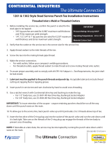
761/741 Shut Off • Divert • Reverse Acting
Key # Description 1" 11/2"2"2
1/2"3" 4"
1L 10/20 Actuator, Long Not Available 25-428-S 25-428-S 25-428-S 25-428-S 25-467-S
1L 30 Actuator, Long Not Available 25-466-S 25-466-S 25-466-S 25-466-S 25-517-S
1LHD Light Duty 4½" Dia. Actuator, Long Not Available Not Available Not Available Not Available Not Available 25-457-S
1M Mid Position Actuator Not Available 25-454-S 25-454-S 25-454-S 25-454-S Not Available
1S 10/20 Actuator, Short 25-448B-S 25-436-S 25-436-S 25-436-S 25-436-S 25-497-S
1S 30 Actuator, Short 25-475-S 25-465-S 25-465-S 25-465-S 25-465-S 25-519-S
2A Stem Protector, Long Not Available Not Available Not Available Not Available Not Available 25-455-08A
2B Stem Protector, O-Ring Not Available Not Available Not Available Not Available Not Available 17-158-U
2C Stem Protector, Spacer Not Available Not Available Not Available Not Available Not Available 25-457-10-316L
2L Stem Protector, Long Not Available 25-428-08 25-428-08 25-428-08 25-428-08 Not Available
2S Stem Protector, Short 25-436-08 25-436-08 25-436-08 25-436-08 25-436-08 25-428-08
3L Yoke, Long Not Available 12-495-S 12-495-S 12-495-S 12-495-S 12-516-316
3LI Yoke, Long (741) Not Available 12-495I-S 12-495I-S 12-495I-S 12-495I-S 12-516-316
3S Yoke, Short 12-496-S 12-496-S 12-496-S 12-496-S 12-496-S 12-533-316L
3SI Yoke, Short (741) 12-496I-S 12-496I-S 12-496I-S 12-496I-S 12-496I-S 12-533I-316L
*4 Seal Retainer* 25-428-05 25-428-05 25-428-05 25-428-05 25-428-05 25-428-05
*5 V-Packing* 17-98 17-98 17-98 17-98 17-98 17-98
* 5a O-Ring to replace V-Packing 17-284-Mat'l 17-284-Mat'l 17-284-Mat'l 17-284-Mat'l 17-284-Mat'l 17-284-Mat'l
6 Packing Retainer 25-428-04 25-428-04 25-428-04 25-428-04 25-428-04 25-428-04
7 End Cap 25-428-06A 25-428-06A 25-428-06A 25-428-06A 25-428-06A 25-455-06
8 Red Caplug 12-493 12-493 12-493 12-493 12-493 12-493
9 Vent Plug (not shown) MS-105-58A-CP MS-105-58A-CP MS-105-58A-CP MS-105-58A-CP MS-105-58A-CP MS-105-58A-CP
10 Lockwasher LWA1300-SS LWA1300-SS LWA1300-SS LWA1300-SS LWA1300-SS LWA1300-SS
11 Screw SC1308H-SS SC1308H-SS SC1308H-SS SC1308H-SS SC1308H-SS SC1309H-SS
12 Screw SC1312H-SS SC1312H-SS SC1312H-SS SC1312H-SS SC1312H-SS SC1312H-SS
*13 O-Ring* 17-5-U 17-17-U 17-17-U 17-17-U 17-17-U 17-89-U
*14 O-Ring* 17-4-U 17-4-U 17-4-U 17-4-U 17-4-U 17-4-U
*15 O-Ring* 17-35-U 17-35-U 17-35-U 17-35-U 17-35-U 17-35-U
*16 O-Ring* 17-109-U 17-109-U 17-109-U 17-109-U 17-109-U 17-109-U
*17 Nylon Lock Pin* 9-300 9-300 9-300 9-300 9-300 9-300
18 Lower Body, Tee 7-1041TM-1-316L 7-1022TM-11/2-316L 7-1022TM-2-316L 7-1022TM-21/2-316L 7-1022TM-3-316L 7-225TM-4-316L
18I Lower Body, Tee (741) 7-104ICMIA-1-316L 7-1022TMIA-11/2-316L 7-1022TMIA-2-316L 7-1022TMIA-21/2-316L 7-1022TMIA-3-316L 7-225TMI-4-316L
18A Lower Body, (27 & 47) Not Available 7-1053M-11/2-316L 7-1053M-2-316L 7-1053M-21/2-316L 7-1053M-3-316L Not Available
19 Lower Body, Cross 7-1041CM-1-316L 7-1022CM-11/2-316L 7-1022CM-2-316L 7-1022CM-21/2-316L 7-1022CM-3-316L 7-225CM-4-316L
19I Lower Body, Cross (741) 7-1041CMIA-1-316L 7-1022CMIA-11/2-316L 7-1022CMIA-2-316L 7-1022CMIA-21/2-316L 7-1022CMIA-3-316L 7-225CMI-4-316L
*20 Gasket 42MP-U-2 17-325-11/2-U 17-325-11/2-U 17-325-21/2-U 17-325-3-U 17-62-41/2-U
21 Clamp 13MHHM-2-S 13MHHVM-3-S 13MHHVM-3-S 13MHHVM-4-S 13MHHM-5-S H13MHHM-4-S
“I” in Key # means industrial upolished finish
*It is recommended that one of each of these items be stocked as spare parts.
Replacement Parts Kits
For your convenience, commonly replace parts (marked with an asterisk above) are available in
economical seal and O-Ring parts kits for 11/2" through 3" sizes valves only. Order pre-
packaged parts kit, #RK761.
- 19 -
Additional Parts for Shut Off Valves - Type 10 & 30
Key # Description 1" 11/2"2"2
1/2"3" 4"
*22 Rubber Stem/Seat Assembly 19-1293-316L 19-1254-11/2-316L 19-1254-2-316L 19-1254-21/2-316L 19-1254-3-316L 19-1254A-4-316L
*23 "TR" Stem/Seat Assembly 19TR-1293-316L 19TR-1254-11/2-316L 19TR-1254-2-316L 19TR-1254-21/2-316L 19TR-1254-3-316L 19TR-1254A-4-316L
*24 "TR" Snap-On Seat 20-514-1 20-514-11/220-514C-2 20-514C-21/220-514C-3 20-514C-4
25 Bonnet 12-499-316L 12-487-11/2-316L 12-487-11/2-316L 12-487-21/2-316L 12-487-3-316L 12-515-316L
26 Split Stem Bushing 40-68 40-63 40-63 40-63 40-63 40-73
Additional Parts for Divert & Reverse Acting Shut Off Valves - Type 21, 23, 27, 41, 43 & 47
Key # Description 1" 11/2"2"2
1/2"3" 4"
*27L Rubber Stem/Seat Assy, Long Not Available 19-1255A-11/2-316L 19-1255A-2-316L 19-1255A-21/2-316L 19-1255B-3-316L 19-1255A-4-316L
*27S Rubber Stem/Seat Assy, Short Not Available 19-1276-11/2-316L 19-1276-2-316L 19-1276-21/2-316L 19-1276-3-316L Not Available
*28L "TR" Stem/Seat Assy, Long Not Available 19TR-1255-11/2-316L 19TR-1255-2-316L 19TR-1255-21/2-316L 19TR-1255-3-316L 19TR-1255A-4-316L
*28S "TR" Stem/Seat Assy, Short Not Available 19TR-1276-11/2-316L 19TR-1276-2-316L 19TR-1276-21/2-316L 19TR-1276-3-316L Not Available
*29U "TR" Snap-On Seat Upper Not Available 20-514C-2 20-514C-2 20-514C-21/220-514C-3 20-514C-4
*29L "TR" Snap-On Seat Lower Not Available 20-514C-11/220-514C-2 20-514C-21/220-514C-3 20-514C-4
*30 Upper Body, Tee Not Available 7-1024TM-11/2-316L 7-1024TM-2-316L 7-1024TM-21/2-316L 7-1024TM-3-316L 7-1024ATM-4-316L
30I Upper Body, Tee (741) Not Available 7-1024TMIA-11/2-316L 7-1024TMIA-2-316L 7-1024TMIA-21/2-316L 7-1024TMIA-3-316L 7-1024ATMI-4-316L
31 Upper Body, Cross Not Available 7-1024CM-11/2-316L 7-1024CM-2-316L 7-1024CM-21/2-316L 7-1024CM-3-316L 7-1024ACM-4-316L
31I Upper Body, Cross (741) Not Available 7-1024CMIA-11/2-316L 7-1024CMIA-2-316L 7-1024CMIA-21/2-316L 7-1024CMIA-3-316L 7-1024ACMI-4-316L
32 Split Stem Bushing Not Available 40-64 40-64 40-64 40-64 40-75
33 Seal Retaining Washer Not Available 15-171-316L 15-171-316L 15-171-316L 15-171-316L 15-175-316L
*34L Rubber Stem/Seat Assy Long
(27 & 47 Only) Not Available Not Available Not Available Not Available Not Available 19-1377-4-316L
*34S Rubber Stem/Seat Assy Short
(27 & 47 Only) Not Available 19-1306-2-316L 19-1306-2-316L 19-1306-21/2-316L 19-1306-3-316L Not Available
*35L "TR" Stem/Seat Assy Long
(27 & 47 Only) Not Available Not Available Not Available Not Available Not Available 19TR-1377-316L
*34S "TR" Stem/Seat Assy Short
(27 & 47 Only) Not Available 19TR-1306-2-316L 19TR-1306-2-316L 19TR-1306-21/2-316L 19TR-1306-3-316L Not Available
“I” in Key # means industrial upolished finish
*It is recommended that one of each of these items be stocked as spare parts.
Replacement Parts Kits
For your convenience, commonly replace parts (marked with an asterisk above) are available in
economical seal and O-Ring parts kits for 11/2" through 3" sizes valves only. Order pre-
packaged parts kit, #RK761.
  • Page 1 1
  • Page 2 2
  • Page 3 3
  • Page 4 4
  • Page 5 5
  • Page 6 6
  • Page 7 7
  • Page 8 8
  • Page 9 9
  • Page 10 10
  • Page 11 11
  • Page 12 12
  • Page 13 13
  • Page 14 14
  • Page 15 15
  • Page 16 16
  • Page 17 17
  • Page 18 18
  • Page 19 19
  • Page 20 20
  • Page 21 21
  • Page 22 22
  • Page 23 23
  • Page 24 24
  • Page 25 25
  • Page 26 26
  • Page 27 27
  • Page 28 28
  • Page 29 29
  • Page 30 30
  • Page 31 31

Tri-Clover 762 Series Service & Installation Manual

Type
Service & Installation Manual
This manual is also suitable for

Ask a question and I''ll find the answer in the document

Finding information in a document is now easier with AI