V68H Pressure relief valve
Installation & Maintenance Instructions
6/15
I&M/en 8.260.500.01
Our policy is one of continued research and development. We therefore reserve the right to amend,
without notice, the specifications given in this document. (1999 - I&M8095c) © 2015 IMI International s.r.o.
Fluid: Compressed air
Maximum pressure: 20 bar (300 psig)
Operating temperature*:
–20° ... +80°C (0° ... +175°F)
* Air supply must be dry enough to avoid ice
formation at temperatures below +2°C (+35°F).
Gauge ports:
1/8 PTF with PTF yoke ports
Rc1/8 with ISO Rc yoke ports
Rc1/8 with ISO G yoke ports
Exhaust port:
1” PTF with PTF yoke ports
Rc1 with ISO Rc yoke ports
Rc1 with ISO G yoke ports
Materials:
Body: Aluminium
Intermediate body: Aluminium
Bonnet: Aluminium
Bottom plug: Aluminium
Adjusting screw: Steel
Elastomers: Synthetic rubber
Yoke: Aluminium
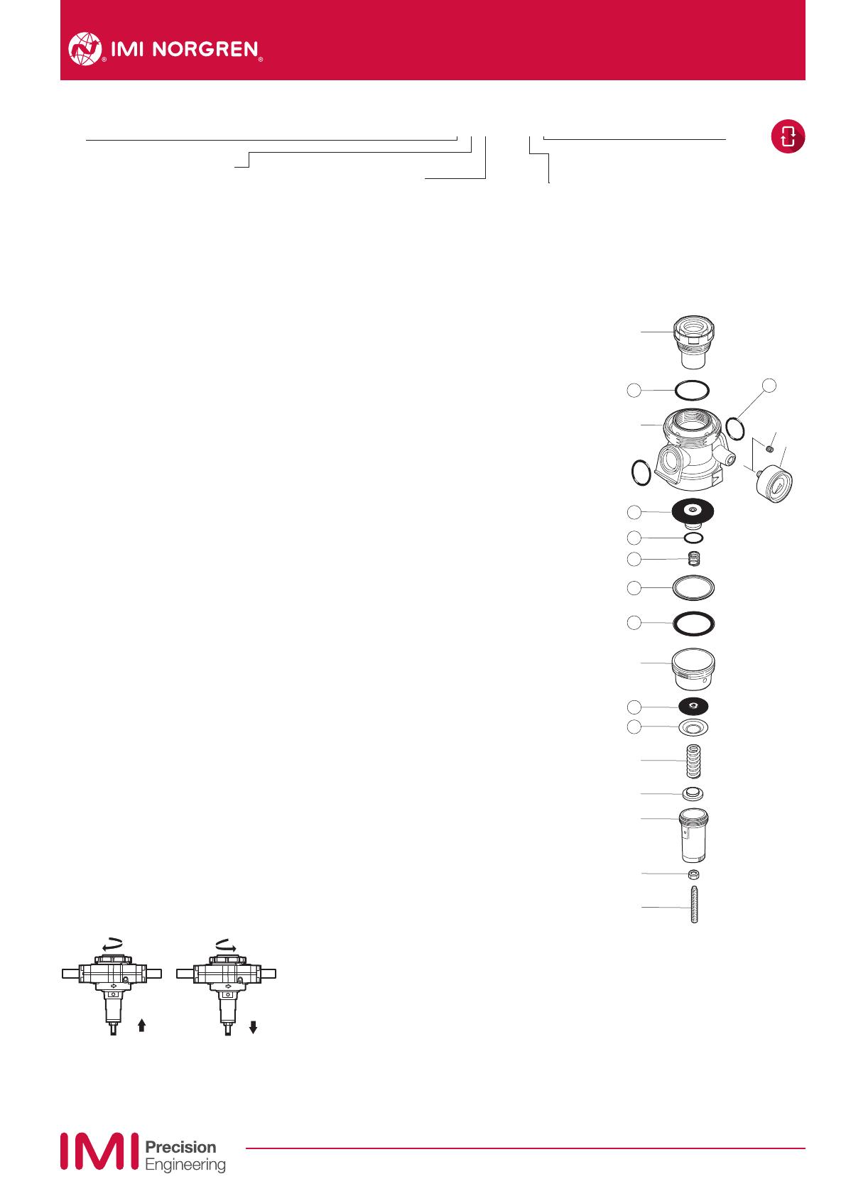
Replacement Items
Service kit
(items circled on exploded view) 4384-300
Installation
1. Install yoke in air line -
• with air ow in direction of arrow on top of
yoke,
• as close as possible to the device being
served,
• at any angle.
2. Connect piping to yoke ports using pipe
thread sealant on male threads only.
3. Install a pressure gauge or plug gauge ports.
4. Lubricate o-rings (17) with a light coat of
o-ring grease, then place o-rings in grooves in
body (16).
5. Place clamp ring under lugs on top of yoke.
6. Make sure arrows on yoke and relief valve
point in same direction, then plug relief valve
into yoke and tighten clamp ring hand tight.
Warning
Do not cap or in any way restrict the outlet
port of the relief valve. Relief port must be
open to atmosphere.
Adjustment
1.Turn relief valve adjustment clockwise to
increase pressure setting. Turn adjustment
counterclock wise to decrease pressure
setting.
2. Always approach the desired pressure from
a lower pressure. When reducing from a
higher to a lower setting, first reduce to some
pressure less than that desired, then bring up
to the desired pressure.
Disassembly
1. Shut o inlet pressure. Reduce pressure in
inlet and outlet lines to zero.
2. Turn adjustment (3) fully counterclockwise.
3. Unscrew clamp ring and remove regulator
from yoke.
4. Disassemble in general accordance with the
item numbers on exploded view.
Cleaning
1. Clean parts with warm water and soap.
2. Rinse and dry parts. Blow out internal
passages in body with clean, dry
compressed air.
3. Inspect parts. Replace those found to be
damaged.
Assembly
1. Lubricate o-rings, gasket (9), adjusting screw
threads and tip (3) and the recess of spring
rest (4) with a light coat of good quality o-ring
grease. Apply grease to both sides of gasket
(9).
2. Lubricate threads on bonnet (1), intermediate
body (8), and plug (14) with a small amount of
anti-seize compound.
3. Assemble the unit as shown on the exploded
view.
Torque in Item N-m (Inch-Pounds)
1 (Bonnet) 62 ... 68 (550 ... 600)
8 (Intermediate body) 62 ... 70 (550 ... 620)
18 (Pipe plug) 3,3 ... 5,5 (29 ... 49)
19
15
2
1
4
7
6
3
5
8
9
12
13
10
17
14
16
11
18
Technical features
Port
6 3/4“
8 1“
A 1-1/4“
B 1-1/2“
N No yoke
Thread
A PTF
B ISO Rc tapered
G ISO G parallel
N No yoke (N in 5th position) Rc gauge ports.
A No yoke (N in 5th position) PTF gauge ports
V68H – ˙˙˙ – R˙˙
Adjustment
D Slotted screw Spring (Outlet pressure range) *
F 0,3 ... 4 bar (3 ... 60 psig)
M 0,3 ... 10 bar (3 ... 150 psig)
S 0,7 ... 17 bar (10 ... 250 psig)
* Relief valves can be adjusted to pressures in excess of, and less than, those specified. Do not use these units to control pressures outside of the specified ranges.
Gauge
G With
N Without
Option selector

