Page is loading ...

USER GUIDE
GPU WATER BLOCK
EK-Quantum
Vector² Strix/TUF RTX 4090 D-RGB ABP Set

Please note the installation of the product is intended to be undertaken
by an adequately trained and experienced person. You are installing the
product at your own risk. If you are not properly trained or experienced
or feel unsure about the installation procedure, please refrain from
installing the product yourself and contact our tech support for
assistance. We disclaim our liability for any damages to the product as
well as incidental, consequential, or indirect damages incurred due to
improper or inappropriate installation.
Before you start using this product, please follow these basic guidelines:
Carefully read the manual before beginning with the
installation process.
Remove your graphics card from the computer for the safest
mounting process to prevent any possible damage to your
GPU or its circuit board (PCB).
The EK Fittings require only a small amount of force to screw
them firmly in place since the liquid seal is ensured by the
rubber O-ring gaskets.
The use of corrosion-inhibiting coolants is always
recommended for liquid cooling systems and mandatory for
nickel-plated water blocks!
Do not use pure distilled water!
For best results, EK recommends the use of EK-CryoFuel
coolants! To reach optimal performance, make sure to
thoroughly bleed the air out of your water block!

- 3 -
TABLE OF CONTENTS
BOX CONTENTS 4
BOX CONTENTS – Rev 2 5
WATER BLOCK DIMENSIONS 6
DIFFERENCE BETWEEN Rev 1 AND Rev 2 COLDPLATE 7
TECHNICAL SPECIFICATIONS AND WATER BLOCK PARTS 8
NICKEL PLEXI 8
NICKEL ACETAL 9
PREPARING THE GRAPHICS CARD 10
REMOVING THE STOCK COOLER 10
ASUS TUF GAMING GEFORCE RTX 4090 10
PREPARING THE WATER BLOCK FOR INSTALLATION 12
CUTTING AND PLACING THERMAL PADS 14
CUTTING AND PLACING THERMAL PADS - Rev 2 14
APPLYING THERMAL COMPOUND 15
ATTACHING THE WATER BLOCK 16
OPTION 1: USING ASUS GEFORCE RTX 4090 STRIX 17
OPTION 2: ASUS GEFORCE RTX 4090 TUF GAMING 18
ATTACHING THE AC TIVE BACKPL ATE 19
ATTACHING THE ACTIVE BACKPLATE - Rev 2 20
FITTINGS AND TUBING 21
INSERTING THE GRAPHICS CARD INTO THE CHASSIS 22
CONNECTING THE D-RGB LED STRIP 22
TESTING THE LOOP 23
WARRANTY 23
SUPPORT AND SERVICE 24
SOCIAL MEDIA 24

- 4 -
120 mm
24 mm
Thermal Grease (1 pc)
BOX CONTENTS
4 mm
8 mm
10 mm
EK-Loop Multi Allen Key
(1 pc)
Allen Key 2 mm (1 pc)
Allen Key 2.5 mm (1 pc)
M2.5x6 AX1 Screw (1 pc) M2.5x8 AX1 Screw (1 pc)
Replacement I/O Bracket (1 pc)
M3x10 AX1 Screw (1 pc)
EK-Quantum Vector2 Strix/TUF RTX 4090 D-RGB
ABP Set
M2.5x4 AX1 Screw (11 pcs)
Polyamid Washer M2.5 0.5mm
(11 pcs)
Standoff Ø4.5/2.5 (1 pc)
Quantum Plug (2 pcs)
EK-Plug Out Spludger Tool
(1 pc)
Standoff M2.5-M3 x 6.6mm
(1 pc)
M3 x 6 DIN7991 Screw
(2 pc)
Nut M2.5 (2 pcs)
Terminal OR - Vector2 14x1 mm
(2 pcs)
EAN: 105934
EAN: 106046
Thermal Pad F 1.0 mm (6 pcs)
(3830046996732)
Thermal Pad F 1.5 mm (4 pcs)
(3830046996749)
Thermal Pad G 2.0 mm (3 pcs)
(3830046996794)
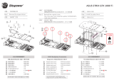
120 mm
16 mm
120 mm
16 mm
6 mm

- 5 -
120 mm
24 mm
120 mm
24 mm
Thermal Grease (1 pc)
BOX CONTENTS – Rev 2
4 mm
8 mm
10 mm
EK-Loop Multi Allen Key
(1 pc)
Allen Key 2 mm (1 pc)
Allen Key 2.5 mm (1 pc)
M2.5x6 AX1 Screw (1 pc) M2.5x8 AX1 Screw (1 pc)
Replacement I/O Bracket (1 pc)
M3x10 AX1 Screw (1 pc)
EK-Quantum Vector2 Strix/TUF RTX 4090 D-RGB
ABP Set
M2.5x4 AX1 Screw (11 pcs)
Polyamid Washer M2.5 0.5mm
(11 pcs)
Standoff Ø4.5/2.5 (1 pc)
Quantum Plug (2 pcs)
EK-Plug Out Spludger Tool
(1 pc)
Standoff M2.5-M3 x 6.6mm
(1 pc)
M3 x 6 DIN7991 Screw
(2 pc)
Nut M2.5 (2 pcs)
Terminal OR - Vector2 14x1 mm
(2 pcs)
EAN: 105934
EAN: 106046
Thermal Pad F 1.0 mm (6 pcs)
(3830046996732)
Thermal Pad G 1.5 mm (4 pcs)
(3830046996787)
Thermal Pad G 2.0 mm (3 pcs)
(3830046996794)
120 mm
16 mm
6 mm

- 6 -
WATER BLOCK DIMENSIONS
260 mm
115.1 mm
143.1 mm
153 mm
141 mm
41 mm
35.5 mm

- 7 -
DIFFERENCE BETWEEN Rev 1 AND Rev 2 COLDPLATE
Before installing the water block, check the version of the coldplate.
Rev 1 Rev 2

- 8 -
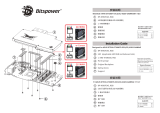
TECHNICAL SPECIFICATIONS AND WATER BLOCK PARTS
NICKEL PLEXI
- Dimensions: (L x H x W): 260 x 153 x 41 mm
- D-RGB LED count: 24
- D-RGB cable length: 50 cm
- D-RGB connector 3-pin 5V digital LED header
Position EAN Description Quantity
1.1 105919 Coldplate (Ni) Rev 1 1
1.2 106227 Coldplate (Ni) Rev 2 1
2.1 105920 Top plate (Plexi) Rev 1 1
2.2 106228 Top plate (Plexi) Rev 2 1
3105926 LED Cover (Nat. Elox) 2
4103962 Plexi insert 1
5103987 Standoff M3.5-M2.5 x 3 mm 4
6103988 Standoff M4-M2.5 x 3 mm 4
7103986 Standoff M3.5-M2.5 x 11.3 mm 6
8103942 Terminal Badge 1
9104216 Disc magnet 3 x 3 4
10 104106 Terminal OR -14 x 1 mm 4
11 8311 Screw M4 x 20 DIN7984 6
12 105561 Replacement I/O Bracket (Black) 1
13 8472 Screw M3 x 6 DIN7991 2
14 8208 Screw M3 x 8 7991DIN 2
15 100663 EK - Badge 2
16 103964 Mylar sticker 2
17 9024 Screw M4 x 10 DIN7984 13
18 104099 Stand out (Acetal) 1
19 105991 FC Terminal bridge (Ni) 1
20 105989 FC Terminal (Acetal) 1
21 8201 Screw M3 x 10 DIN7991 2
22 104414 OR 52 x 2 mm 1
23 104086 ABP Terminal Badge 1
24 105931 Sideplate (Bl. Elox) 1
25.1 105981 Coldplate ABP (Ni) Rev 1 1
25.2 106232 Coldplate ABP (Ni) Rev 2 1
26.1 105927 Top plate ABP (Plexi) Rev 1 1
26.2 106233 Top plate ABP (Plexi) Rev 2 1
27 104093 Standoff M2.5-M3 x 6.6 mm 5
28 104105 Screw AX1 M3 x 10 mm 5
29 9013 Screw M4 x 8 DIN7984 13
30 105932 Main OR 150 x 2 mm 1
31 105933 Main OR ABP 147 x 2 mm 1
32 105935 PCB cardboard 1
33 100815 LED D-RGB strip 500/300 mm 2
8
23
15
7
30
21
18
19
24
14
31
27
11
32
1
4
2
9
20
22
10
17
33
25
3
12
6
5
13
28
16
26
29

- 9 -
NICKEL ACETAL
- Dimensions: (L x H x W): 260 x 153 x 41 mm
- D-RGB LED count: 38
- D-RGB cable length: 50 cm
- D-RGB connector 3-pin 5V digital LED header
Position EAN Description Quantity
1.1 105919 Coldplate (Ni) Rev 1 1
1.2 106227 Coldplate (Ni) Rev 2 1
2.1 105921 Top plate (Acetal) Rev 1 1
2.2 106230 Top plate (Acetal) Rev 2 1
3103962 Plexi insert 1
4103987 Standoff M3.5-M2.5 x 3 4
5103988 Standoff M4-M2.5 x 3 mm 4
6103986 Standoff M3.5-M2.5 x 11.3 mm 6
7103942 Terminal Badge 1
8104216 Disc magnet 3 x 3 4
9104106 Terminal OR 14 x 1 mm 4
10 8311 Screw M4 x20 DIN7984 6
11 105561 Replacement I/O Bracket (Black) 1
12 8472 Screw M3 x 6 DIN7991 2
13 100663 EK - Badge 2
14 9024 Screw M4 x 10 DIN7984 13
15 104296 LED D-RGB Strip 500/130 mm 1
16 8202 Screw M3 x 12 DIN7991 2
17 104211 Mylar sticker 2
18 105991 FC Terminal bridge (Ni) 1
19 105989 FC Terminal (Acetal) 1
20 8201 Screw M3 x 10 DIN7991 2
21 104414 OR 52 x 2 mm 1
22 104086 Terminal Badge 1
23 105931 Sideplate (Bl. Elox) 1
24.1 105981 Coldplate ABP (Ni) Rev 1 1
24.2 106232 Coldplate ABP (Ni) Rev 2 1
25.1 105928 Top plate ABP (Acetal) Rev 1 1
25.2 106234 Top plate ABP (Acetal) Rev 2 1
26 104093 Standoff M2.5-M3 x 6.6 mm 5
27 104105 Screw AX1 M3 x 10 5
28 9013 Screw M4 x 8 DIN7984 13
29 104102 Stand Out (Acetal) 1
30 104096 Light Guide 1
31 105932 Main OR 150 x 2 mm 1
32 105933 Main OR ABP 147 x 2 mm 1
33 105935 PCB cardboard 1
7
5
3
22
21
16
15
17
9
29
23
13
6
32
26
10
27
20
18
11
19
8
14
4
28
2
12
31
33
24
25
1

- 10 -
PREPARING THE GRAPHICS CARD
REMOVING THE STOCK COOLER
ASUS TUF GAMING GEFORCE RTX 4090
Important! Before starting, make sure to have a clean, flat
surface to work on. It is recommended to put foam or soft
material to lay the graphics card on.
STEP 1
First, remove eight (8) screws from the backside of the Stock cooler
(using Phillips head screwdriver).
STEP 2
Unscrew three (3) screws from the I/O Bracket (using Phillips head
screwdriver). Unplug the connectors in order to remove the stock
cover from the GPU PCB.
STEP 1
STEP 2

- 11 -
STEP 3
From the front side of the GPU, an additional two (2) screws must be
removed (using Phillips head screwdriver). Detach the GPU Backplate.
STEP 4
Rotate the GPU and unscrew four (4) Screws from the retention
bracket (using Phillips head screwdriver). Remove the bracket and
Stock Cooler from the GPU PCB.
STEP 3
STEP 4
RETENTION
BRACKET
STOCK
COOLER

- 12 -
Allen Key 2.5mm
TERMINAL
BADGE
PREPARING THE WATER BLOCK FOR INSTALLATION
STEP 1
First, remove the terminal badge which is attached to the terminal with
two magnets. Under the badge, unscrew three (3) screws M4 x 20
DIN7984. Additional five (5) screws M3 x 10 AX1 need to be removed
(as shown in the image). Save the removed parts for later use.
DO NOT REMOVE THE UPPER TERMINAL BADGE!
STEP 1
For this step, you will need:
Phillips Head Screwdriver
M3 x 10 AX1 SCREW
M4 x 20 DIN7984 SCREW
UPPER TERMINAL BADGE
STEP 5
Lastly, unscrew four (4) Screws and detach the I/O Bracket (using
Phillips head screwdriver).
EK provides the replacement I/O Bracket with the water block.
STEP 5
I/O BRACKET

- 13 -
STEP 3
STEP 3
Unscrew five (5) M2.5-M3 x 6.6 standoffs with the provided
tool (EK-Plug out Spludger Tool). Make sure not to unscrew
the M3.5-M2.5 x 11.3 standoffs! In case the M3.5-M2.5 x 11.3
standoffs unscrew, carefully tighten it back with the 4 mm
wrench. After removing the standoffs, the PCB cardboard needs
to be removed. Save the removed parts for later use.
M2.5-M3x6.6 STANDOFF
M3.5-M2.5x11.3 STANDOFF
STEP 2
STEP 2
Carefully remove the complete active backplate with the terminal.
Additional two (2) O-rings 14 x 1 mm needs to be removed.
ACTIVE BACKPLATE
TERMINAL O-RING
14 x 1 mm
For this step, you will need:
EK-Plug Out Spludger Tool
PCB
CARDBOARD

- 14 -
STEP 1
CUTTING AND PLACING THERMAL PADS
Thermal Pad F – 1.0 mm (120 x 16 mm)
120 mm
16 mm
1 mm
STEP 1
The GPU water block comes with thermal pads that have to be cut
into smaller pieces to cover all the VRM components, such as COILs,
MOSFETs, and drivers.
Remove the protective foil from both sides of the thermal
pad before installation.
Replacement thermal pads:
Thermal Pad F 1.0 mm – (120 x 16 x 1 mm) EAN: 3830046996732
Thermal Pad F 1.5 mm – (120 x 16 x 1.5 mm) EAN: 3830046996749
Thermal Pad G 2.0 mm – (120 x 16 x 2 mm) EAN: 3830046996794
Thermal Pad F – 1.5 mm (120 x 16 mm)
1.5 mm
120 mm
16 mm
Thermal Pad G – 2.0 mm (120 x 24 mm)
120 mm
24 mm
2 mm
STEP 1
CUTTING AND PLACING THERMAL PADS - Rev 2
STEP 1
The GPU water block comes with thermal pads that have to be cut
into smaller pieces to cover all the VRM components, such as COILs,
MOSFETs, and drivers.
Remove the protective foil from both sides of the thermal
pad before installation.
Replacement thermal pads:
Thermal Pad F 1.0 mm – (120 x 16 mm) EAN: 3830046996732
Thermal Pad G 1.5 mm – (120 x 24 mm) EAN: 3830046996787
Thermal Pad G 2.0 mm – (120 x 24 mm) EAN: 3830046996794
Thermal Pad F – 1.0 mm (120 x 16 mm)
120 mm
16 mm
1 mm
Thermal Pad G – 2.0 mm (120 x 24 mm)
120 mm
24 mm
2 mm
Thermal Pad G – 1.5 mm (120 x 24 mm)
120 mm
24 mm
1.5 mm

- 15 -
STEP 2
Once cut to the size, Thermal Pads should be placed on the PCB, as
shown in the picture:
STEP 2
Thermal Pad - 120 x 16 x 1.0 mm
F1
Thermal Grease
STEP 1
Apply the enclosed thermal grease (thermal compound) on the
GPU heat spreader – IHS – as shown in the image. The layer of the
thermal compound must be thin and even over the entire surface
of the IHS.
The excessive or uneven application of thermal grease
may lead to poor performance!
APPLYING THERMAL COMPOUND
For this step, you will need:
STEP 1

- 16 -
ATTACHING THE WATER BLOCK
STEP 1
Position the replacement I/O Bracket on the water block. During this
process, make sure you have aligned the holes. Secure it with the
two (2) M3 x 6 DIN7991 Screws and Allen Key 2 mm.
STEP 1
For this step, you will need:
Replacement I/O
Bracket
Allen Key 2 mm
M3 x 6 DIN7991
Screw (2 pcs)
REPLACEMENT I/O BRACKET
M3 x 6 DIN7991 SCREW
STEP 2
STEP 2
Carefully place the water block with preinstalled standoffs and
replacement I/O Cover on the GPU PCB. During this process, make
sure you have aligned the mounting holes of the PCB with the holes
of the water block.
Pay attention not to use too much force when pressing
the block down to the PCB since chip dies are prone
to cracking.
Before placing the Water Block, make sure all the Thermal
Pads are placed correctly!

- 17 -
For this step, you will need:
Phillips Head Screwdriver
STEP 3
OPTION 1: USING ASUS GEFORCE RTX 4090 STRIX
Use nine (9) M2.5 x 4 AX1 screws and PVC washers to tighten
the GPU PCB. Tighten the screws evenly using the Phillips-head
screwdriver. EK recommends you start tightening the screws
around the GPU core first and then continuing outward to prevent
damaging the GPU. Always use a plastic washer under each screw.
After attaching the water block, three (3) saved Factory provided
I/O Bracket screws can be reused.
M2.5 x 4 AX1 SCREW
M2.5 PVC WASHER
I/O BRACKET SCREW
Screws must be present in the places marked on the picture.
STEP 3

- 18 -
STEP 3
OPTION 2: ASUS GEFORCE RTX 4090 TUF GAMING
Use nine (9) M2.5 x 4 AX1 screws and PVC washers to tighten the
GPU PCB. An additional one (1) M2.5 x 6 AX1 Screw must be secured
with an M2.5 Nut. Tighten the screws evenly using the Phillips-head
screwdriver. EK recommends you start tightening the screws around
the GPU core first and then continuing outward to prevent damaging
the GPU. Always use a plastic washer under each screw.
After attaching the water block, three (3) saved Factory provided
I/O Bracket screws can be reused.
M2.5 x 4 AX1 SCREW
M2.5 PVC WASHER
I/O BRACKET SCREW
M2.5 x 6 AX1 SCREW
M2.5 NUT
Screws must be present in the places marked on the picture.
STEP 3

- 19 -
STEP 4
After securing the GPU PCB, position the five (5) M2.5-M3 x 6.6
standoffs. Tighten it with the provided tool (EK-Plug out Spludger
Tool).
STEP 4
M2.5-M3 x 6.6
STAN DO FF
For this step, you will need:
EK-Plug Out Spludger Tool
ATTACHING THE ACTIVE BACKPLATE
STEP 1
After attaching the water block, a few more thermal pads need to be
placed on the backside of the GPU PCB. Once cut to size, thermal
pads should be placed, as illustrated. EK made sure to provide you
with more than an adequate quantity of thermal pads to complete
this Step.
Replacement thermal pads:
Thermal Pad F 1.0 mm – (120 x 16 mm) EAN: 3830046996732
Thermal Pad F 1.5 mm – (120 x 16 mm) EAN: 3830046996749
Thermal Pad G 2.0 mm – (120 x 16 mm) EAN: 3830046996794
STEP 2
Thermal Pad - 120 x 16 x 1.5 mm
F1.5
Thermal Pad - 120 x 24 x 2.0 mm
G2
F1.5 F1.5
F1.5G2
G2
G2
F1.5

- 20 -
ATTACHING THE ACTIVE BACKPLATE - Rev 2
STEP 1
After attaching the water block, a few more thermal pads need to be
placed on the backside of the GPU PCB. Once cut to size, thermal
pads should be placed, as illustrated. EK made sure to provide you
with more than an adequate quantity of thermal pads to complete
this Step.
Replacement thermal pads:
Thermal Pad F 1.0 mm – (120 x 16 mm) EAN: 3830046996732
Thermal Pad G 1.5 mm – (120 x 24 mm) EAN: 3830046996787
Thermal Pad G 2.0 mm – (120 x 24 mm) EAN: 3830046996794
STEP 2
G1.5 G1.5
G1.5G2
G2
G1.5
G2
STEP 2
Insert two (2) O-rings (14 x 1 mm) into slots on the cold plate. Then
carefully place the active backplate on standoffs (as shown in the
image). While putting the active backplate on the PCB, make sure
the O-rings stay in the slots.
Before attaching the Active Backplate, make sure all the
Thermal Pads are placed correctly!
STEP 2
ACTIVE BACKPLATE
OR 14 x 1 mm
Thermal Pad - 120 x 24 x 2.0 mm
G2
Thermal Pad - 120 x 24 x 1.5 mm
G1.5
/