
43
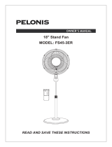
2. Insert the blade into shaft, and make sure the rotor shaft pin is fitted into groove
of the blade. Turn the spinner counterclockwise to tighten the blade. (Fig. 6)
3. Fasten the front grill and the rear grill by the grill clip and then tighten the fan
grill locking screw and nut. (Fig. 7)
GRILL & FAN BLADE ASSEMBLY
1. Unscrew the spinner clockwise (or take the spinner out from the bag) and the
plastic nut counterclockwise to remove both of them. Fix the rear grill to the
motor then tighten the plastic nut again. (Fig. 5)
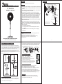
OPERATING INSTRUCTION
1. Speed is controlled by the piano switch.
0---Off 1---Low 2---Medium 3---High
2. To make/stop the fan head oscillate.
Push down/pull up the clutch knob.
3. To adjust the air flow upward or downward, push the
grilles lightly to the desired direction.
4. The height of the fan can be adjusted by loosening the
height adjustment ring carefully raising or lowering the fan
and firmly re-tightening the height adjustment ring.
16" Stand Fan
MODEL: RM/159
Version 1.0 2015
Attention: Pictures in the IM are for reference only.
READ AND SAVE THESE INSTRUCTIONS
The fan requires little maintenance. Do not try to fix it by yourself.
Refer it to qualified service personnel if service is needed.
1. Before cleaning and assembling, fan must be unplugged.
2. To ensure adequate air circulation to the motor, keep vents at the rear of the
motor free of dust. Do not disassemble the fan to remove dust.
3. Please wipe the exterior parts with a soft cloth soaking a mild detergent.
4. Do not use any abrasive detergent or solvents to avoid scratching the surface.
Do not use any of the following as a cleaner: gasoline, thinner.
5. Do not allow water or any other liquid into the motor housing or interior parts.
MAINTENANCE INSTRUCTION
CLEANING
1. Be sure to unplug from the electrical supply source before cleaning.
2. Plastic parts should be cleaned with a soft cloth moisten with mild soap.
Thoroughly remove soap film with dry cloth.
21
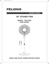
PART FIGURE
1
0
2
3
Read Rules for Safe Operation and Instructions Carefully.
CAUTION
1. If the supply cord is damaged, it must be replaced by manufacturer
or its service agent or a similarly qualified person in order to avoid
a hazard.
2. To protect against the risk of electrical shock, do not immerse the
unit, cord or plug in water or other liquid.
3. This appliance is not intended for use by persons (including
children) with reduced physical, sensory or mental capabilities, or
lack of experience and knowledge, unless they have been given
supervision or instruction concerning use of the appliance by a
person responsible for their safety. Young children should be
supervised to ensure that they do not play with the appliance.
4. When the appliance is not in use and before cleaning, unplug the
appliance from the outlet.
5. Keep electrical appliances out of reach from Children or infirm
persons. Do not let them use the appliances without supervision.
6. When the fan was assembled, the rotor blade guard shall not be
taken off anymore
- Prior cleaning unplug the fan.
- The rotor guard shall not be dissembled/opened to clean the
rotor blades.
- Wipe the fan enclosure and rotor blade guard with a slightly
damp cloth.
WARNING
1. Never insert fingers, pencils, or any other object through the grille when fan is
running.
2. Disconnect fan when moving from one location to another.
3. Be sure fan is on a stable surface when operating to avoid overturning.
4. DO NOT use fan in window, rain may create electrical hazard.
5. Household use only.
RULES FOR SAFE OPERATION
Spinner
Front grill
Rear grill
Fan blade Plastic nut Motor shaft
Clutch knob
Motor housing
Piano
switch
Tighten
Loosen
Note: All the pictures in this manual are for
explanation purpose only. Any discrepancy
between the real object and the illustration
in the drawing shall be subject to the real
subject.
Extension Pole
Internal Pole
Timer
switch
Thumb
screw
Height
Adjustment
Ring
Circlip
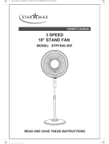
ASSEMBLY OF CHASSIS & COLUMN UNIT
Fig.5 Fig.6 Fig.7
Chassis
7-shape Bolt
1. Unscrew the 7-shape Boltfrom the Extension Pole. (Fig.1)
2. Insert the extension pole into the chassis and tighten the 7-shape Bolt (Fig.2)
3. From the extension pole loosen the height adjustment ring and adjust the internal
pole to the desired height. (Note: If you can’t find the internal pole, it must inside
the extension pole. You can pull it out from the extension pole.) (Fig.3)
4. To attach the head unit to the internal pole, loosen the thumb screw on the bottom
of the head unit. Place the head unit on the internal pole and tighten the thumb
screw in alignment with the groove on the internal pole. (Fig.4)
CAUTION: Height adjustment ring must be fully fastened before the assembly of the
motor section to the internal pole.
Annulargroove
Mountinghole
Thumb screw
Fig.3
Looseen
Fig.4
Fig.1Fig.2
OWNER’S MANUAL
-
 1
1

Ask a question and I''ll find the answer in the document
Finding information in a document is now easier with AI
Related papers
Other documents
-
Morris MFS-16220 Instructions Manual
-
Defy Stand Fan DSF 1626W Owner's manual
-
Sunpentown SF16T07 User manual
-
 Pelonis FS45-3ER Owner's manual
-
BLACK DECKER BFSR18 User manual
-
-
 Star Max STFFS45-3DF Owner's manual
-
 Hampton Bay FS40-21MA User guide
-
 Pelonis FS45-3ER Owner's manual
-
COMFORT-AIRE FP-1830DTOM-PBL Owner's manual


