Page is loading ...

52415-10 March 2010
Thermo Fisher Scientific
TZ-28
Instruction Manual

© 2009 Thermo Fisher Scientific Inc. All rights reserved.
ULTRACRIMP< is either a registered trademark or a trademark of Thermo Fisher Scientific.
All other trademarks are the property of Thermo Fisher Scientific Inc. and its subsidiaries.
Thermo Fisher Scientific Inc. provides this document to its customers with a product purchase to use in the
product operation. This document is copyright protected and any reproduction of the whole or any part of this
document is strictly prohibited, except with the written authorization of Thermo Fisher Scientific Inc.
The contents of this document are subject to change without notice. All technical information in this
document is for reference purposes only. System configurations and specifications in this document supersede
all previous information received by the purchaser.
Thermo Fisher Scientific Inc. makes no representations that this document is complete, accurate or error-
free and assumes no responsibility and will not be liable for any errors, omissions, damage or loss that might
result from any use of this document, even if the information in the document is followed properly.
This document is not part of any sales contract between Thermo Fisher Scientific Inc. and a purchaser. This
document shall in no way govern or modify any Terms and Conditions of Sale, which Terms and Conditions of
Sale shall govern all conflicting information between the two documents.
Release history: 52415-10 printed in March 2010.
For Research Use Only. Not for use in diagnostic procedures.

Thermo Scientific TZ-28 i
T
Thermo Scientific TZ-28 Zonal Rotor in the Ultracentrifuge ............................................ ii
Important Safety Information ................................................................................................. iii
Chapter 1 DESCRIPTION ........................................................................................................................ 1-1
Rotor Description .................................................................................................... 1-2
Rotor Specifications ................................................................................................. 1-2
Parts and Accessories ................................................................................................ 1-3
Rate Controller ........................................................................................................ 1-3
Chapter 2 OPERATION ............................................................................................................................ 2-1
Rotor Holding Fixture ............................................................................................. 2-2
Prerun Safety Check ................................................................................................ 2-2
Compartment Loads in Excess of Design Mass ........................................................ 2-3
Critical Speed .......................................................................................................... 2-3
Relative Centrifugal Force (RCF) Determination .................................................... 2-3
Calculation of Sedimentation in Aqueous (Non-Gradient) Solutions ...................... 2-6
Chemical Compatibility .......................................................................................... 2-7
Rotor Assembly, Loading and Operation ................................................................. 2-7
Centrifuge/Rotor Log ............................................................................................ 2-13
Chapter 3 MAINTENANCE ...................................................................................................................... 3-1
Corrosion ................................................................................................................ 3-2
Cleaning .................................................................................................................. 3-2
Overspeed Decal Replacement ................................................................................. 3-3
Service Decontamination Policy .............................................................................. 3-3
Chemical Compatibility Chart ...............................................................................A-1
Contact Information ................................................................................................B-1
Table of contents


Thermo Scientific TZ-28 ii
P
This manual is a guide for the use of
Thermo Scientific TZ-28 Zonal Rotor in the
Ultracentrifuge
Data herein has been verified and is believed adequate for the intended use of the rotor. Because failure
to follow the recommendations set forth in this manual could produce personal injury or property
damage, always follow the recommendations set forth herein. Thermo Fisher Scientific does not
guarantee results and assumes no obligation for the performance of rotors or other products that are
not used in accordance with the instructions provided. This publication is not a license to operate
under, nor a recommendation to infringe upon, any process patents.
Publications prior to the Issue Date of this manual may contain data in apparent conflict with that
provided herein. Please consider all data in this manual to be the most current.
NOTES, CAUTIONS, and WARNINGS within the text of this manual are used to emphasize
important and critical instructions.
WARNING informs the operator of a hazard or unsafe practice that could result in personal injury,
affect the operator's health, or contaminate the environment.
CAUTION informs the operator of an unsafe practice that could result in damage of equipment.
NOTE highlights essential information.
© 1993,1999, 2010 by Thermo Fisher Scientific
CAUTION and WARNING are accompanied by a hazard symbol and appear near the
information they correspond to.

Preface
iii TZ-28 Thermo Scientific
Important Safety Information
Certain potentially dangerous conditions are inherent to the use of all centrifuge rotors. To ensure safe
operation of this rotor, anyone using it should be aware of all safe practices and take all precautions
described below and throughout this manual.
WARNING
When using radioactive, toxic, or pathogenic materials, be aware of all characteristics of
the materials and the hazards associated with them in the event leakage occurs during
centrifugation. In the event of a rotor failure, neither the centrifuge nor the rotor can
protect you from particles dispersed in the air. To protect yourself, we recommend
additional precautions be taken to prevent exposure to these materials, for example, use of
controlled ventilation or isolation areas.
Always be aware of the possibility of contamination when using radioactive, toxic, or
pathogenic materials. Take all necessary precautions and use appropriate decontamination
procedures if exposure occurs.
Never use any material capable of producing flammable or explosive vapors.
Never exceed the maximum rated speed of the installed rotor; to do so can cause rotor
failure.
Always reduce (derate) rotor speed as instructed in this manual whenever the
compartment load exceeds the maximum allowable compartment load specified. See
Chapter 2.
Failure to reduce the rotor speed under these conditions can cause rotor failure.
CAUTION
Do not expose aluminum rotor components to: strong acids, bases, or alkaline laboratory
detergents; liquid chlorine bleach; or salts (chlorides) of heavy metals such as cesium, lead,
silver, or mercury. Use of these materials with aluminum can cause a chemical reaction that
initiates corrosion.
Do not operate the rotor at the critical speed, as this will have a detrimental effect on
centrifuge component life. See Chapter 2, Operation.
Do not operate the rotor unless it is balanced as described in this manual. Operating the
rotor out of balance can cause damage to the centrifuge drive assembly.
Do not operate the rotor unless it is properly seated on the drive spindle and locked in
place. See Chapter 2, Operation.
Always maintain the rotor in the recommended manner. The rotor, seals, and all
accessories must be clean and inspected prior to each run: do not use rotors showing signs
of corrosion or cracking. See Chapter 3, Care and Maintenance.

Thermo Scientific TZ-28 1-1
1
DESCRIPTION
This manual provides the information you will need to operate and maintain your TZ-28 Zonal Rotor
when used in your Thermo Scientific Ultracentrifuge. If you require additional information regarding
operation or maintenance, please contact Thermo Fisher Scientific for assistance. In the United States,
call Thermo Fisher Scientific toll-free 1-866-9THERMO; outside the United States, contact the
nearest Thermo Fisher Scientific office (see back cover) or your local representative for Thermo Fisher
Scientific products. Thermo Fisher Scientific product information is available on our internet web site
at http:// www.thermo.com/centrifuge .
.
Contents
•“Rotor Description” on page 1-2
•“Rotor Specifications” on page 1-2
•“Parts and Accessories” on page 1-3
•“Rate Controller” on page 1-3

1 DESCRIPTION
Rotor Description
1-2 TZ-28 Thermo Scientific
Rotor Description
The TZ-28 Rotor consists of a rotor body, septa, rotor cover, and feed adapter. The rotor body and
cover are machined from a titanium forging for strength and corrosion resistance. The rotor body is
painted black for surface protection and temperature regulation. The Valoxo septa is inserted into the
rotor body to divide the rotor into six sector-shaped compartments. The rotor cover is fitted with a
large O-ring that seals the rotor body during operation.
This manual describes assembly and operation of the TZ-28 Rotor for use in Thermo Fisher
Scientific Ultracentrifuges. The TZ-28 can also be adapted for use in Thermo Fisher Scientific
Refrigerated Superspeed Centrifuges. To operate the TZ-28 Rotor in Thermo Fisher Scientific
Refrigerated Superspeed Centrifuges refer to Instruction Manual, Cat. No. 49618 and the Rotors,
Tubes, Bottles, and Adapters Product Guide for additional kits and accessories required for
superspeed centrifuge operation.
Ultracentrifuge Conversion Kit, Catalog No. 12271
The Ultracentrifuge Conversion Kit adapts the TZ-28 Rotor for use in the ultracentrifuge. This kit
consists of a drive adapter, tapered adapter, distributor body, holddown plate, sealing cover and
overspeed decal. The drive adapter and tapered adapter allow the TZ-28 Rotor to be installed in the
ultracentrifuge, while the distributor body and holddown plate allow equal distribution of the
gradient and sample to the six sector-shaped compartments. The sealing cover permits operation in a
vacuum and the overspeed decal provides overspeed protection. Refer to Table 4-1 for a complete list
of parts supplied in this kit. O-rings of Viton A and Buna N are used in the rotor assembly and
components of the Ultracentrifuge Conversion Kit where an airtight seal is required
Rotor Specifications
Table 1-1.Rotor Specifications
Rotor Type Zonal
Maximum Speed 28 000 rpm*
*Speed in revolutions per minute (rpm) is related to angular velocity, ω, according to the following:
Where ω = rad/s. All further references to speed in this manual will be designated as rpm.
Relative Centrifugal Force (RCF) at Maximum Speed:
- rminimum (3.65cm) 31701
- rmaximum (9.53 cm) 83 457
Total Capacity (Nominal) 1350 ml
Diameter 21.33 cm (8.40 in)
Mass (Weight) 7.80 kg (17.2 lb)
Critical Speed 800 rpm
Design Load 1350 ml at 1.2 average specific gravity
K Factor at Maximum Speed 312
ω(rpm)=2π
60
------
⎝⎠
⎛⎞ rpm()0.10472()=

1 DESCRIPTION
Parts and Accessories
Thermo Scientific TZ-28 1-3
Parts and Accessories
Parts supplied with the TZ-28 Rotor, Catalog No. 52358, are listed in Table 1-2. To perform the
operating procedures described in this manual it is necessary to have additional accessories not supplied
with the TZ-28 Rotor Assembly. Table 1-3 lists additional accessories required to run the TZ-28 Rotor
in an Ultracentrifuge.
To order replacement parts and accessories, telephone 1-866-9THERMO) in the United States.
Outside the United States, contact your local representative for Thermo Fisher Scientifi products. To
ensure you receive the correct part for your rotor be sure to provide a description of the part, catalog
number, rotor model and serial number.
Rate Controller
To override the centrifuge's electronic speed control, which is programmed for fast acceration and slow
deceleration, an ARC-1 Automatic Rate Controller is required on the Thermo Fisher Scientific
OTD-2, OTD-50, and OTD-65 Ultracentrifuges.
Precise control of the rate acceleration and deceleration in the range of 0 rpm to 1000 rpm is critical for
the function of the TZ-28 Rotor sincereorientation occurs in this period. In addition, the ARC-1
Automatic Rate Controller will prevent the refrigeration compressor and fan from starting and
disturbing the gradient during the critical speed period.
Refer to Table 1-2 to determine the appropriate rate controller for your centrifuge. For proper
operation of the rate controller, follow the operating instructions supplied with the rate controller and
the ultracentrifuge.
Table 1-2. Accessories Supplied
Quantity Catalog Number Description
1 52540 Rotor Holding Fixture (including mounting screws)
49609 Septa
49007 Feed Adapter
66026 Dissecting Needle
49724 Wrench
49026 T-Wrench Assembly
61556 Antigalling Grease (2 oz.)
63037 O-ring, .489 ID x .070 thk, Viton<
12 66193 O-ring, .176 ID x .070 thk, Viton<
2 65755 O-ring, 7.237 ID x .103 thk, Viton<
Note When using the TZ-28 Rotor in a Thermo Fisher Scientific OTD-55B, OTD-65B or
OTD-75B Ultracentrifuge, use the REOGRAD Mode of operation for slow acceleration and
deceleration. Refer to the Ulracentrifuge Instruction Manual, Cat. No. 52844, for instructions
required to set the REOGRAD Mode.

1 DESCRIPTION
Rate Controller
1-4 TZ-28 Thermo Scientific
Table 1-3.Additional Accessories Required
Description Catalog Number
Ultracentrifuge Conversion Kit 12271
Automatic Rate Controller for the OTD-2 Ultracentrifuge 52130
Automatic Rate Controller for the OTD-50/65/75 Ultracentrifuge 52270
Syringe with blunt 18 gauge needle*
*This item is not available through Thermo Fisher Scientific products.

Thermo Scientific TZ-28 2-1
2
OPERATION
Contents
•“Rotor Holding Fixture” on page 2-2
•“Prerun Safety Check” on page 2-2
•“Compartment Loads in Excess of Design Mass” on page 2-3
•“Critical Speed” on page 2-3
•“Relative Centrifugal Force (RCF) Determination” on page 2-3
•“Calculation of Sedimentation in Aqueous (Non-Gradient) Solutions” on page 2-6
•“Chemical Compatibility” on page 2-7
•“Rotor Assembly, Loading and Operation” on page 2-7
•“Centrifuge/Rotor Log” on page 2-13

2 OPERATION
Rotor Holding Fixture
2-2 TZ-28 Thermo Scientific
Rotor Holding Fixture
The rotor holding fixture (Catalog No. 52540) is used to hold the rotor during rotor loading and
unloading procedures to prevent disturbances of the gradient. Secure the rotor holding fixture to a
workbench with the two flathead screws supplied as shown in figure 2-1.
Figure 2-1. Rotor Holding Fixture Installation
Prerun Safety Check
To ensure safe performance of the rotor, the following items should be checked before every run:
•level the rotor to ensure equal dispersion of the density gradient,
•make sure the rotor spud hole is clean and free of encrusted material,
•inspect the O-rings in the rotor assembly for cracks, tears or abrasions; replace if necessary,
•remove any blockage from the lines of the septa, distributor, and holddown plate,
•lubricate the threads of the rotor body with antigalling grease,
•check the overspeed decal on the bottom of the tapered adapter for damage; replace if necessary,
and
•make sure all rotor parts and accessories have been cleaned as explained in paragraph 3-2.
WARNING Failure to properly maintain your rotor can cause rotor failure with
subseguent damage to your centrifuge. Also, depending on the sample being processed,
rotor failure can result in biological or radioactive contamination. Therefore, every part of
the rotor must be clean and should be carefully inspected before every run. If there is any
sign of corrosion or cracking, the rotor should not be used.
2 OPERATION
Compartment Loads in Excess of Design Mass
Thermo Scientific TZ-28 2-3
Compartment Loads in Excess of Design Mass
There is a recommended design mass established for each rotor representing the maximum mass that
can be carried in the rotor. To prevent rotor failure, the total mass should not exceed the recommended
figure unless rotor speed is reduced proportionately. If the density of the solution is greater than 1.2
g/ml use the following formula to determine the reduced speed:
Critical Speed
The critical speed is that speed at which any rotor imbalance will produce a driving frequency equal to
the resonant frequency of the rotating system (i.e., the rotor and the centrifuge drive). At this speed, the
rotor may produce large amplitude vibrations which can be felt in the instrument frame. Mass
imbalance will contribute to increased vibration intensity at the critical speed. Avoid operating the
rotor at the critical speed which is approximately 800 rpm for the TZ-28 Rotor.
Relative Centrifugal Force (RCF) Determination
Relative Centrifugal Force (RCF) refers to the force during centrifu-gation that moves the particulate
outward from the center of rotation. This force is proportional to the radial distance and the square of
the rotor speed. The RCF value is determined by the following:
when r = the radius in centimeters from the centerline of the rotor to the point in the tube where
RCF value is required
and rpm = the rotor speed in revolutions per minute
Reduced Speed 28000 1.2 g/ml
Average Fluid Density
---------------------------------------------------=
CAUTION Continued operation at the critical speed will have a detrimental effect on
centrifuge component life.
RCF 11.17(r)=rpm
1000
------------
⎝⎠
⎛⎞
2
2 OPERATION
Relative Centrifugal Force (RCF) Determination
2-4 TZ-28 Thermo Scientific
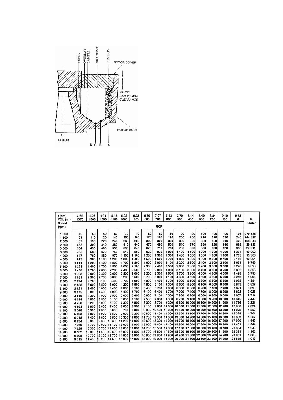
Figure 2-2 represents the volume occupied by a liquid within the spinning rotor in relation to the
maximum radius of the rotor, 9.531cm (3.75 inches). The points marked A, B, C, and D in figure
2-3 correspond to inflection points on the curve in figure 2-2 and may be used as a reference.
Figure 2-2. Volume vs. Radius
2 OPERATION
Relative Centrifugal Force (RCF) Determination
Thermo Scientific TZ-28 2-5
Figure 2-3. TZ-28 Zonal Rotor Cross Section
Table 2-1 list volumes along with their inside vertical surface radii. The determination of RCF can be
helpful when a cushion is used since the actual forces exerted against the sample can be accurately
noted. For example, if a 100 ml cushion and a 900 ml gradient were used, then the sample introduced,
the forces developed on the sample at 10 000 rpm will range from 6600 at the free fluid surface of the
gradient to 10 300 rpm at the interface of gradient and cushion.
Table 2-1. Tz-28 Rotor: RCF Values and K Factors

2 OPERATION
Calculation of Sedimentation in Aqueous (Non-Gradient) Solutions
2-6 TZ-28 Thermo Scientific
Table 2-1.Tz-28 Rotor: RCF Values and K Factors
Calculation of Sedimentation in Aqueous (Non-Gradient) Solutions
The time required to sediment a particle in water at 20°C through the maximum rotor path length
(i.e., the distance between rminimum and rmaximum can be estimated using the equation:
where:
t = sedimentation time in hours
K = the clearing factor for the rotor (defined on the next page)
S20, w = the sedimentation coefficient for the particle of interest in water at 20°C as expressed
in Svedbergs1
The clearing (or K) factor is defined by the equation:
Where rmaximum and rminimum are the maximum and minimum rotor radii, respectively, and rotor
speed is expressed in rpm.
K factors for the TFT-80.2 Rotor,at speeds from 20 000 rpm to 80 000 rpm (in increments of 500
rpm), are listed in Table 2-1.
1 The sedimentation coefficient (S) in seconds, for a particle in a centrifugal field is defined by the equation S =
(dx/dt) [1/(ω2x)]; where dx/dt = sedimentation velocity of the particle in cm/s; ω = rotor speed in rad/s; and x
= the distance of the particle from the axis of rotation in centimeters. Conventionally, experimentally
determined values of sedimentation coefficients are multiplied by 1013 to convert them to Svedberg units (S),
so a particle with an experimentally determined sedimentation coefficient of 10-11 seconds is usually referred to
in the literature as a "100 S particle." Since the value determined for the sedimentation coefficient is dependent
on the density and viscosity of the solution in which centrifugation is performed, values are usually reported for
the standard conditions of infinite dilution in water at 20°C, and designated S20, w.
tK
S20,w
-------------
=
K 253000()In rmaximum
rminimum
--------------------
⎝⎠
⎛⎞
rotor speed
1000
-------------------------
⎝⎠
⎛⎞
2
÷=

2 OPERATION
Chemical Compatibility
Thermo Scientific TZ-28 2-7
Example: The TZ-28 Rotor has a K factor of 312 at the maximum permitted speed (28 000 rpm). If
the particles to be sedi-mented have a sedimentation coefficient of 100S, the estimated run
time required at maximum speed will be:
Note that the calculation assumes particles in water at 20°C. If the suspending medium is denser or
more viscous than water, the sedimentation time will be greater.
Chemical Compatibility
The critical components of the TZ-28 Rotor that are apt to come in contact with solution are: rotor
body and rotor cover (titanium), septa (Valox<), holddown plate (aluminum), feed adapter and
distributor body (Delrin<), drive adapter and tapered adapter (stainless steel) and O-rings (Viton< of
Buna N).
The chemical compatibility of rotor elements and accessory materials is given in Annex A. Because no
organized chemical resistance data exists for materials under the stress of centrifugarion, the data is
intended to be used only as a guide. When in doubt, we recommend pretesting of sample lots.
Rotor Assembly, Loading and Operation
a. Rotor Assembly and Precooling
1. Insert the tapered adapter (Catalog No. 52496), into the bottom of the rotor body, no alignment is
required (see figure 2-4)
t312
100S
-----------
=3.12 hours 3 hours, 7 minutes=
Note The tapered adapter and drive adapter are shipped as an assembly and must be disassembled
before assembling the rotor.
If your desired application requires precooling of the rotor gradient and sample, be sure to precool
your gradient and sample separately. Follow the instructions below to precool your rotor in the
ultracentrifuge. If desired, you can precool your rotor to the required temperature in a refrigerator
then assemble the rotor following steps 1 through 11 below and proceed to step b. Rotor Loading.
Use figures 2-5 and 2-6 for parts location and identification.
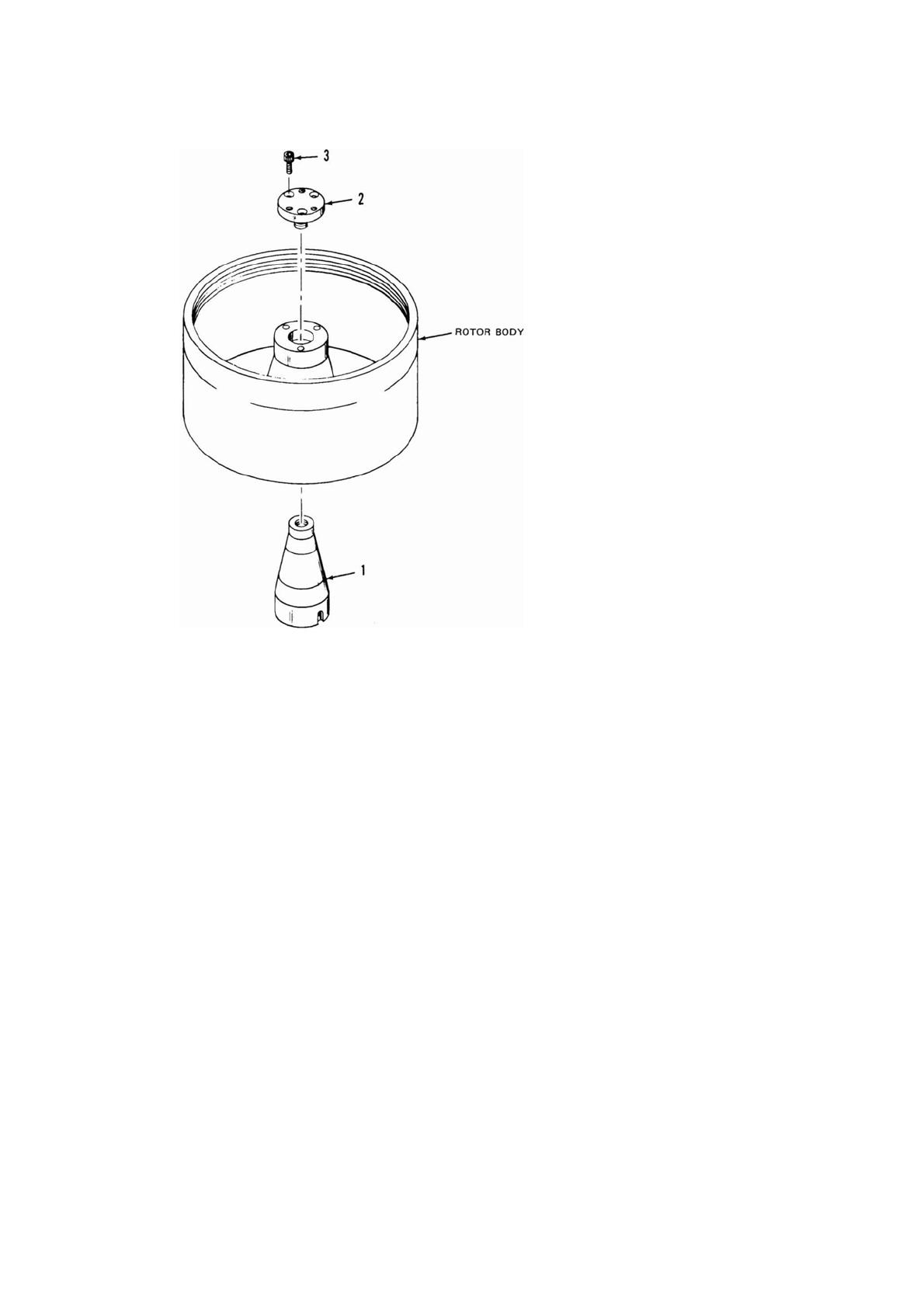
Table 2-2. TZ-28 Adapter Assembly (key to figure 2-4)
Item Quanty Catalog Number Description
1 1 52496 Tapered Adapter
2 1 52418 Drive Adapter
3 3 60912 Socket Head Screw (8-32 x 3/8 long)
- 1 51363 Overspeed Decal*
*Overspeed decal is located on bottom of rotor.
2 OPERATION
Rotor Assembly, Loading and Operation
2-8 TZ-28 Thermo Scientific
Figure 2-4. Adapter assembly
2. Thread the drive adapter (Catalog No. 52418) into the tapered adapter and turn it until the
screw holes are aligned with those in the rotor body. Insert the three socket head screws (Catalog
No. 60912) into the corresponding three holes in the drive adapter. Use the T-wrench (Catalog
No. 49026) to loosely righted the screws.
3. From underneath the rotor body, use the tapered adapter wrench (Catalog No. 52497) to tighted
the tapered adapter (turning clockwise).
4. Firmly tighted the three socket head screws in the drive adapter (step 2).
5. Slide the rotor into the rotor holding fixture.
6. Using the dissecting needle (Catalog No. 66026) suplied, carefully remove the O-rings in the
rotor assembly. Inspect each of the O-rings for cracks, tears of abrasions; replace if necessary.
Lubricate each O-ring with a light film of vacuum grease (Catalog No. 65937), then reinsert
each O-ring into its respective part.
7. Place the septa into the rotor body using a twisting motion.
8. Lubricate the threads of the rotor cover at several places around the circumference with
antigalling grease (Catalog No. 61556). Place the rotor cover onto the rotor body, then turn it
clockwise until it drops onto the threads of the rotor body. Turn the cover counterclockwise until
tight (this will spread the grease over the threads). Use wrench assembly (Catalog No. 49724) to
securely tighted the cover.

2 OPERATION
Rotor Assembly, Loading and Operation
Thermo Scientific TZ-28 2-9
9. Use both hands to remove the rotor assembly from the rotor holding fixture and carefully lower it
onto the drive spindle.
10. Check that the rotor is levelby placing a spirit level on the flat surface of the rotor cover (this will
ensure equal dispersion of the gradient during operation).
11. Place the distributor body (Catalog No. 52425) in position through the hole in the rotor cover.
Slowly rotate the distributor body to engage the guide pins, located on the bottom of the
distributor body, with the corresponding holes in the septa.
12. Place the holddown plate (Catalog No. 52416) on the distributor body (the top of the holddown
plate can be identified by the three large screw holes). Align the three screw holes of the holddown
plate with the corresponding holes in the distributor body. Insert the three socket head screws (Cat.
No. 62987) throught both parts. Turn the assembly (holddown plate, distributor body and septa)
while pressing down firmly on one of the screws until it aligns with the corresponding threaded
hole of the rotorbody and drops into place. Use the T-wrench to alternately tighted the screws until
they are firmly and evenly tightened.
13. If required, precool the rotor in a refrigerator or cold room.
b. Rotor Loading
1. With the rotor at rest and the ultracentrifuge door open, connect the silicone tubing from a
peristaltic pump to the feed adapter (Catalog No. 49007). Insert the feed adapter into the center of
the distributor body.
2. Check that all lines are loading gradient properly. Turn the peristaltic pump on, then squeeze the
silicone tubing near the feed adapter to create a back pressure. When the tubing is released the fluid
should purge the air from all loading lines resulting in an even flow of fluid through all channels.
Repeat this prodecure to ensure all lines are loaded evenly.
3. Load the gradient into the rotor using the peristaltic pump, light end first. The gradient must flow
smoothly through all loading lines or it will be distributed unevenly between the six compartments
of the septa.
4. When all the gradient is loaded, remove the feed adapter (including silicone tubing) from the
distributor body.
5. Use a syringe with a blunt 18 gauge needle to load equal amounts of sample into each of the six
holes in the holddown plate.
CAUTION Before running the TZ-28 Rotor in the ultracentrifuge, make sure the rotor
cover is properly seated. Clearance between the rotor body and cover (see figure 2-3)
should not be greater than 0.64mm(0.025 inches). Operating the rotor with the cover not
properly seated can cause rotor failure with subsequent damage to your ultrcentrifuge.
CAUTION Always run the TZ-28 Rotor with a full fluid load (1350 ml). Failure to run the
rotor with less than a full load may cause damage to the ulrtracentrifuge and/or rotor due
to the shifting mass of the fluid and may cause the septa to disintegrate. If enough sample
is not available an overlay should be used to increase the rotor contents to 1350 ml.

2 OPERATION
Rotor Assembly, Loading and Operation
2-10 TZ-28 Thermo Scientific
6. Place the sealing cover (Catalog No. 52417) over the distributor body. Insert the three socket
head screws (Catalog No. 66329) into the sealing cover and align with the distributor body. Use
the T-wrench to alternately tighten the screws.
7. Close the centrifuge door and perform the run as explained in the ultracentrifuge instruction
manual.
c. Acceleration and Deceleration
1. Acceleration - Acceleration should be at a slow, smooth rate, taking from five (5) to ten (10)
minutes to reach 1000 rpm. Follow the instructions supplied with the Automatic Rate
Controller.
2. Centrifugation - When the rotor speed reaches 1000 rpm, use normal operating procedures for
the centrifuge and automatic rate controller to complete the desired run.
3. Deceleration - Use normal deceleration to 1000 rpm. Below 1000 rpm deceleration should be at
a slow, smooth rate taking from five (5) to ten (10) minutes to go from 1000 rpm to 0 rpm. For
slow deceleration, refer to the instruction manual supplied with your Thermo Fisher Scientific
Ultracentrifuge.
d. Unloading and Disassembling the Rotor
1. At the end of the run, carefully open the centrifuge door.
2. Use the T-wrench to remove the three socket head screws from the sealing cover. Remove the
sealing cover.
3. Relubricate the feed adapter O-ring (Catalog No. 63037) with vacuum grease (Catalog No.
65937).
4. Connect the silicone tubing from the peristaltic pump to the feed adapter. Then, insert the feed
adapter into the center of the distributor body.
5. Before unloading the rotor, check that all lines unload evenly and smoothly as follows:
a. Set the speed control of the peristaltic pump to a higher rate than normal.
b. Turn the peristaltic pump on, then squeeze the silicone tubing near the feed adapter to create
a vacuum. Release the tubing (when the tubing is released there should be a rush of bubbles
up through the feed adapter as the feed lines clear). No more bubbles should appear in the
effluent from the distributor body and all lines should unload at the same rate.
c. Reset the speed control of the peristaltic pump to its normal unloading rate.
Note Once the rotor has stopped spinning, be careful not to bump or jar the centrifuge. Any
disturbance may remix the delicate separations.
CAUTION The density gradient being pumped from the rotor must flow smoothly
through all feed lines so the gradient will unload evenly. If the gradient does not unload
evenly, there will be significant loss in the resolution obtained during centrifugation.
/