Page is loading ...

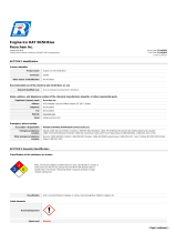
8255-8 March 2010
Thermo Fisher Scientific
T-1270
Instruction Manual

© 2009 Thermo Fisher Scientific Inc. All rights reserved.
ULTRACRIMP< is either a registered trademark or a trademark of Thermo Fisher Scientific.
All other trademarks are the property of Thermo Fisher Scientific Inc. and its subsidiaries.
Thermo Fisher Scientific Inc. provides this document to its customers with a product purchase to use in the
product operation. This document is copyright protected and any reproduction of the whole or any part of this
document is strictly prohibited, except with the written authorization of Thermo Fisher Scientific Inc.
The contents of this document are subject to change without notice. All technical information in this
document is for reference purposes only. System configurations and specifications in this document supersede
all previous information received by the purchaser.
Thermo Fisher Scientific Inc. makes no representations that this document is complete, accurate or error-
free and assumes no responsibility and will not be liable for any errors, omissions, damage or loss that might
result from any use of this document, even if the information in the document is followed properly.
This document is not part of any sales contract between Thermo Fisher Scientific Inc. and a purchaser. This
document shall in no way govern or modify any Terms and Conditions of Sale, which Terms and Conditions of
Sale shall govern all conflicting information between the two documents.
Release history: 8255-8 printed in March 2010.
For Research Use Only. Not for use in diagnostic procedures.

Thermo Scientific T-1270 i
T
Thermo Scientific T-1270 Titanium Fixed-Angle Ultracentrifuge Rotor ......................... ii
Important Safety Information ................................................................................................. iii
Chapter 1 DESCRIPTION ........................................................................................................................ 1-1
Rotor Description .................................................................................................... 1-2
Rotor Specifications ................................................................................................. 1-2
Accessories ............................................................................................................... 1-3
Chapter 2 OPERATION ............................................................................................................................ 2-1
Prerun Safety Checks ............................................................................................... 2-2
Compartment Loads in Excess of Design Mass ........................................................ 2-2
Critical Speed .......................................................................................................... 2-3
Rotor Precool .......................................................................................................... 2-3
Relative Centrifugal Force (RCF) Determination .................................................... 2-3
Calculation of Sedimentation Time in Aqueous (Non-gradient) Solutions .............. 2-7
Chemical Compatibility .......................................................................................... 2-8
Rotor Balancing ....................................................................................................... 2-8
Rotor Loading and Sealing ..................................................................................... 2-10
Tube Removal ....................................................................................................... 2-11
Centrifuge Rotor Log ............................................................................................ 2-11
Chapter 3 CARE and MAINTENANCE ................................................................................................... 3-1
Corrosion ................................................................................................................ 3-2
Cleaning and Decontamination ............................................................................... 3-2
Overspeed Decal Replacement ................................................................................. 3-4
Storage ..................................................................................................................... 3-5
Service Decontamination Policy .............................................................................. 3-5
Chemical Compatibility Chart ...............................................................................A-1
Contact Information ................................................................................................B-1
Table of contents

Thermo Scientific T-1270 ii
P
This manual is a guide for the use of
Thermo Scientific T-1270 Titanium Fixed-Angle
Ultracentrifuge Rotor
Data herein has been verified and is believed adequate for the intended use of the centrifuge. Because
failure to follow the recommendations set forth in this manual could produce personal injury or
property damage, always follow the recommendations set forth herein. Thermo Scientific does not
guarantee results and assumes no obligation for the performance of rotors or other products that are
not used in accordance with the instructions provided. This publication is not a license to operate
under, nor a recommendation to infringe upon, any process patents.
Publications prior to the Issue Date of this manual may contain data in apparent conflict with that
provided herein. Please consider all data in this manual to be the most current.
NOTES, CAUTIONS, and WARNINGS within the text of this manual are used to emphasize
important and critical instructions.
WARNING informs the operator of a hazard or unsafe practice that could result in personal injury,
affect the operator's health, or contaminate the environment.
CAUTION informs the operator of an unsafe practice that could result in damage of equipment.
NOTE highlights essential information.
© 1983,1988, 1998, 1999, 2008, 2010 by Thermo Fisher Scientific
CAUTION and WARNING are accompanied by a hazard symbol and appear near the
information they correspond to.

Preface
iii T-1270 Thermo Scientific
Important Safety Information
Certain potentially dangerous conditions are inherent to the use of all centrifuge rotors. To ensure safe
operation of this rotor, anyone using it should be aware of all safe practices and take all precautions
described below and throughout this manual.
WARNING
When using radioactive, toxic, or pathogenic materials, be aware of all characteristics of
the materials and the hazards associated with them in the event leakage occurs during
centrifugation. In the event of a rotor failure, neither the centrifuge nor the rotor can
protect you from particles dispersed in the air. To protect yourself, we recommend
additional precautions be taken to prevent exposure to these materials, for example, use of
controlled ventilation or isolation areas.
Always be aware of the possibility of contamination when using radioactive, toxic, or
pathogenic materials.
Take all necessary precautions and use appropriate decontamination procedures if
exposure occurs.
Never use any material capable of producing flammable or explosive vapors or creating
extreme exothermic reactions.
Never exceed the maximum rated speed of the installed rotor; to do so can cause rotor
failure.
Always reduce (derate) rotor speed as instructed in this manual whenever:
•the rotor speed/temperature combination exceeds the solubility of the gradient
material and causes it to precipitate.
•the compartment load exceeds the maximum allowable compartment load specified
(the average fluid density is greater than 1.2 g/ml). See Chapter 2, Operation.
Failure to reduce rotor speed under these conditions can cause rotor failure.

Preface
Thermo Scientific T-1270 iv
CAUTION
Do not expose aluminum rotor components to: strong acids, bases, or alkaline laboratory
detergents, liquid chlorine bleach or salts (chlorides) of heavy metals such as cesium, lead,
silver, or mercury. Use of these materials with aluminum can cause a chemical reaction that
initiates corrosion.
Do not operate or precool a rotor at the critical speed, as this will have a detrimental effect
on centrifuge component life. See Chapter 2, Operation.
Do not operate the rotor unless it is symmetrically balanced as described in this manual.
Operating the rotor out of balance can cause damage to the centrifuge drive assembly.
Do not operate the rotor without the cover in position and locked to the centrifuge drive.
See Chapter 2, Operation.
Always maintain the rotor in the recommended manner. All accessories must be clean and
inspected prior to each run: do not use rotor showing signs of corrosion or cracking. See
Chapter 3, Care and Maintenance.
Do not autoclave the aluminum rotor cover or locking nut to temperatures in excess of
100°C.

Thermo Scientific T-1270 1-1
1
DESCRIPTION
This manual contains information required to operate and maintain the Thermo Scientific T-1270
Fixed-Angle Ultracentrifuge Rotor. If you require additional information regarding operation or
maintenance, please contact Thermo Scientific for assistance. In the United States, call Thermo
toll-free 1-866-9THERMO; outside the United States, contact the nearest Thermo Scientific office
(see back cover) or your local representative for Thermo Fisher Scientific products. Thermo Fisher
Scientific product information is available on our internet web site at http://www.thermo.com/rotors .
Contents
•“Rotor Description” on page 1-2
•“Rotor Specifications” on page 1-2
•“Accessories” on page 1-3

1 DESCRIPTION
Rotor Description
1-2 T-1270 Thermo Scientific
Rotor Description
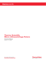
The T-1270 is a twelve-place, fixed-angle, ultracentrifuge rotor that can be used at speeds up to
70,000 rpm.1 The rotor body is made from a titanium forging for strength and corrosion resistance.
The aluminum lid and locking nut are given a blue anodized finish for surface protection. The rotor
is tightly sealed during operation by two O-rings, one that fits inside the rotor lid and another
around the bottom of the locking nut. The twelve tube compartments are bored at a 24° angle to the
axis of rotation. A disc with alternative black and reflective segments attached to the bottom of the
rotor provides overspeed protection.
Rotor Specifications
1Speed in revolutions per minute (rpm) is related to angular velocity, ω, according to the following:
Where ω = rad/s. All further references to speed in this manual will be designated as rpm.
ω(rpm)=2π
60
------
⎝⎠
⎛⎞ rpm()0.10472()=
Table 1-1.Rotor Specifications
Rotor Type Fixed Angle
Maximum Speed (rpm) 70, 000*
*With tubes filled with a non-precipitating homogenous solution having an average density of 1.2 g/ml or
less.
Relative Centrifugal Force (RCF) at Max. Speed
at rmaximum 8.20 cm
at raverage 6.13 cm
at rminimum 4.06 cm
448,811
335,513
222,216
K Factor at Maximum Speed 36.3
Critical Speed (rpm) 3500
Tube Size (mm) 16 mm x 76 mm
(5/8 in x 3 in)
Number of Compartments 12
Capacity per Compartment (Nominal) 11.5 ml
Total Rotor Capacity (Nominal) 138 ml
Maximum Tube Compartment Mass 23 g
Tube Angle 24°
Rotor Diameter 17.2 cm (6.8 inches)
Rotor Weight (Mass) 5.9 kg (13 lbs)

1 DESCRIPTION
Accessories
Thermo Scientific T-1270 1-3
Accessories
Accessories Supplied
The accessories supplied with the T-1270 Rotor, Catalog No. 08259 (rotor with accessories), are listed
in Table 1-2.
For a complete list and description of available Thermo Scientific centrifuges, accessories, rotors, tubes,
bottles, and adapters, please refer to the most current Thermo Fisher Scientific Product Guide. To
order or for information, in the United States, call Thermo toll-free 1-866-9THERMO; outside the
United States, contact the nearest Thermo office (see back cover) or your local representative for
Thermo Fisher Scientific products. Thermo Fisher Scientific product information is available on our
internet web site at http://www.Thermo.com/centrifuge .
Optional Multipiece Sealing Assembly
If you prefer, you can use the T-1270 Rotor with in-walled tubes and multipiecesealing assemblies
previously supplied with the rotor. To do so, you must purchase all items separately: the T-1270 Rotor
with basic accessories only, Catalog No. 08259; a Tool Kit, Catalog No. 52609; the tubes; and sealing
assemblies. Table 1-3 lists the catalog number and description of the tubes and sealing assembly
required, and Table 1-4 lists the parts supplied in the Tool Kit. If you have any of the tools listed, you
do not need to purchase the kit; if necessary, any of the tools listed can be ordered separately by the
catalog number given in the table.
Note In order to seal the ULTRACRIMP< Tubes, you must have an ULTRACRIMP< Sealing Tool,
Catalog No. 03920.
Table 1-2. Accessories Supplied
Quantity Catalog Number Description
1 65937 Vacuum Grease
1 61556 Tube of Lubricant
1 08254 Overspeed Decal, 70 000 rpm (extra)
1 67932 Rotor Cover O-ring (extra)
1 64667 Locking Nut O-ring (extra)
1 52384 Ultraspeed Centrifuge/ Rotor Log Book
1 08255 Instruction Manual
Table 1-3. Optional Multipiece Sealing Assembly Components
Catalog Number Description
03128 Tubes, 12.5 ml, Polyallomer (50/pkg)
52634 Sealing Cap Assembly (each); 12 required

1 DESCRIPTION
Accessories
1-4 T-1270 Thermo Scientific
Rotor Cover Removal Tool
The rotor cover of the T-1270 Rotor is designed to fit the rotor body tightly to ensure a positive seal;
however, because of this tight fit, it is sometimes difficult to remove. If you have difficulty removing
the rotor cover, a removal tool is available, Catalog No. 52652; complete instructions for use of the
tool are supplied with it.
Table 1-4.Tool Kit Parts List for use with Optional Multipiece Sealing Assembly
Catalog Number Description
52176 Tube Cap Vise
52177 Tube Removal Tool
52881 Torque Wrench
52882 Socket, 7/16 inch

Thermo Scientific T-1270 2-1
2
OPERATION
This chapter contains the information necessary to prepare the T-1270 Rotor for operation and
includes important safety information.
Contents
•“Prerun Safety Checks” on page 2-2
•“Compartment Loads in Excess of Design Mass” on page 2-2
•“Critical Speed” on page 2-3
•“Rotor Precool” on page 2-3
•“Relative Centrifugal Force (RCF) Determination” on page 2-3
•“Calculation of Sedimentation Time in Aqueous (Non-gradient) Solutions” on page 2-7
•“Chemical Compatibility” on page 2-8
•“Rotor Balancing” on page 2-8
•“Rotor Loading and Sealing” on page 2-10
•“Tube Removal” on page 2-11
•“Centrifuge Rotor Log” on page 2-11

2 OPERATION
Prerun Safety Checks
2-2 T-1270 Thermo Scientific
Prerun Safety Checks
To ensure safe performance of the rotor, before every run you should:
•read the Important Safety Information on page ii.
•make sure each tube compartment is clean and that there is no sign of corrosion.
•be sure the rotor itself is clean and shows no sign of corrosion or cracking. Also, make sure there
are no scratches or burrs around the rim of the rotor.
•check the centrifuge chamber and drive spindle to be sure they are clean and free of scratches and
burrs.
•verify that the proper overspeed decal is firmly attached to the bottom of the rotor; the decal
must have 13 black segments (refer to page 3-4 for Overspeed Decal Replacement procedure).
•check the chemical compatibility of all materials used (see Table in Appendix).
•inspect the rotor cover O-rings for cracks, tears, or abrasions and replace if necessary. Be sure the
O-rings are properly lubricated (see page 2-10).
•make sure that the rotor cover is on and properly tightened.
•check the top speed capability of the tube or bottle being used; observe the CAUTION.
Compartment Loads in Excess of Design Mass
A recommended design mass has been established for each ultracentrifuge rotor, representing the
maximum mass that each tube compartment can contain during operation. To prevent rotor failure,
the total contents, including specimen, tube, rotor cap, tube cap, and tube plug, should not exceed
the figure given unless rotor speed is reduced proportionately. (If using the optional multipiece
sealing assembly, include the weight of the complete assembly.)
Strict adherence to the maximum allowable compartment mass or reduced speed is required to
prevent rotor failure.
The design mass for each compartment of the T-1270 Rotor is 23 g at 70,000 rpm. This figure is
based on the use of a thinwall polyallomer tube filled with a liquid at 1.2 specific gravity, plus all
sealing assembly components.
CAUTION
When using tubes (or bottles) other than those supplied by Thermo Fisher Scientific, be
sure to check the top speed capability; when in doubt, do a test run for the desired
application. If using a Thermo Fisher Scientific tube (or bottle) other than those supplied
with this rotor, refer to the Product Guide for the maximum speed. Exceeding the top
speed capability of the tube (or bottle) can result in its breakage.
WARNING
Always reduce (derate) rotor speed as instructed in this manual whenever the
compartment load exceeds the maximum allowable compartment load specified. Failure to
reduce rotor speed under these conditions can cause rotor failure.

2 OPERATION
Critical Speed
Thermo Scientific T-1270 2-3
If the compartment mass is greater than 23 g, use the following formula to determine the reduced
speed:
Solubility limits of gradient materials at the operating temperature should never be exceeded.
Critical Speed
The critical speed is that speed at which any rotor imbalance will produce a driving frequency equal to
the resonant frequency of the rotating system (that is, the rotor and the centrifuge drive). At this speed,
the rotor may produce large amplitude vibrations that can be felt in the centrifuge frame. Mass
imbalance contributes to increased vibration intensity at the critical speed. Avoid operating the rotor at
the critical speed, which is approximately 3500 rpm for the T-1270 Rotor. Operation at the critical
speed will have a detrimental effect on centrifuge component life.
Rotor Precool
If samples are routinely processed around 4°C or below, the rotor can be stored in a refrigerator or a
cold room. If this is not possible, the rotor can be precooled easily in a Thermo Fisher Scientific
Ultracentrifuge. Refer to the Ultracentrifuge Instruction Manual for precooling directions. Be careful
not to precool the rotor at its critical speed (read paragraph above).
Relative Centrifugal Force (RCF) Determination
Relative Centrifugal Force (RCF) refers to the force produced duing centrifugation that moves the
particulate outward from the center of rotation. This force is proportional to the radial distance and the
square of the rotor speed. The RCF value is determined by the following formula:
when r = the radius in centimeters from the centerline of the rotor to the point in the tube where
RCF value is required
and rpm = the rotor speed in revolutions per minute
Reduced Speed 70000 23,0g
actual weight
------------------------------=
CAUTION
Do not operate or precool a rotor at the critical speed, as this will have a detrimental effect
on centrifuge component life.
Note The radii values given are the actual rotor cavity specifications; these values do not take the
thickness of the tube into consideration.
RCF 11.17(r)=rpm
1000
------------
⎝⎠
⎛⎞
2

2 OPERATION
Relative Centrifugal Force (RCF) Determination
2-4 T-1270 Thermo Scientific
Figure 2-1. T-1270 Rotor Radii
Figure 2-1 shows the minimum, average, and maximum radii of the T-1270 Rotor. Table 2-1 gives
the RCF value at each radius at speeds from 20 000 rpm to 70,000 rpm in increments of 500 rpm.
The RCF value at any other speed can be calculated by using the above RCF formula.
Table 2-1. T-1270: RCF Values and K Factors*
Speed (rpm) rmax. 8.20 cm
RCF
ravg. 6.13 cm rmin. 4.06 cm K Factors
20,000 36,638 27,389 18,140 445
20,500 38,492 28,775 19,058 423
21,000 40,393 30,196 19,999 403
21,500 42,339 31,651 20,963 385
22,000 44,331 33,140 21,949 367
22,500 46,369 34,664 22,959 351
23,000 48,453 36,222 23,990 336
23,500 50,583 37,814 25,045 322
24,000 52,758 39,440 26,122 309
24,500 54,979 41,100 27,221 296
25,000 57,246 42,795 28,344 285
25,500 59,559 44,524 29,489 274
26,000 61,918 46,287 30,657 263

2 OPERATION
Relative Centrifugal Force (RCF) Determination
Thermo Scientific T-1270 2-5
26,500 64,322 48,085 31,847 253
27,000 66,772 49,916 33,060 244
27,500 69,268 51,782 34,296 235
28,000 71,810 53,682 35,555 227
28,500 74,397 55,616 36,836 219
29,000 77,031 57,585 38,140 211
29,500 79,710 59,588 39,466 204
30,000 82,435 61,625 40,815 198
30,500 85,205 63,696 42,187 191
31,000 88,022 65,802 43,582 185
31,500 90,884 67,941 44,999 179
32,000 93,792 70,115 46,439 174
32,500 96,746 73,324 47,901 168
33,000 99,746 74,566 49,386 163
33,500 102,791 76,843 50,894 158
34,000 105,883 79,154 52,425 154
34,500 109,020 81,499 53,978 149
35,000 112,203 83,878 55,554 145
35,500 115,431 86,292 57,153 141
36,000 118,706 88,740 58,774 137
36,500 122,026 91,222 60,418 133
37,000 125,392 93,738 62,084 130
37,500 128,804 96,289 63,774 126
38,000 132,262 98,874 65,486 123
38,500 135,765 101,493 67,220 120
39,000 139,314 104,146 68,978 117
39,500 142,910 106,834 70,758 114
40,000 146,550 109,555 72,560 111
40,500 150,237 112,311 74,386 108
41,000 153,970 115,102 76,234 106
41,500 157,748 117,926 78,104 103
42,000 161,572 120,785 79,998 101
42,500 165,442 123,678 81,914 98.5
43,000 169,357 126,605 83,853 96.2
43,500 173,319 129,566 85,814 94.0
Table 2-1. T-1270: RCF Values and K Factors*
Speed (rpm) rmax. 8.20 cm
RCF
ravg. 6.13 cm rmin. 4.06 cm K Factors

2 OPERATION
Relative Centrifugal Force (RCF) Determination
2-6 T-1270 Thermo Scientific
44,000 177,326 132,562 87,798 91.9
44,500 181,379 135,592 89,805 89.8
45,000 185,478 138,656 91,834 87.8
45,500 189,622 141,754 93,886 85.9
46,000 193,813 144,887 95,961 84.0
46,500 198,049 148,054 98,058 82.3
47,000 202,331 151,255 100,179 80.5
47,500 206,659 154,490 102,321 78.8
48,000 211,033 157,760 104,487 77.2
48,500 215,452 161,063 106,675 75.6
49,000 219,917 164,402 108,886 74.1
49,500 224,428 167,774 111,119 72.6
50,000 228,985 171,180 113,376 71.1
50,500 233,588 174,621 115,654 69.7
51,000 238,236 178,096 117,956 68.4
51,500 242,930 181,605 120,280 67.1
52,000 247,670 185,149 122,627 65.8
52,500 252,456 188,726 124,996 64.5
53,000 257,288 192,338 127,389 63.3
53,500 262,165 195,984 129,804 62.1
54,000 267,088 199,665 132,241 61.0
54,500 272,057 203,379 134,701 59.9
55,000 277,072 207,128 137,184 58.8
55,500 282,132 210,911 139,690 57.7
56,000 287,239 214,729 142,218 56.7
56,500 292,391 218,580 144,769 55.7
57,000 297,589 222,466 147,343 54.7
57,500 302,833 226,386 149,939 53.8
58,000 308,122 230,340 152,558 52.9
58,500 313,458 234,329 155,200 52.0
59,000 318,839 238,351 157,864 51.1
59,500 324,266 242,408 160,551 50.2
60,000 329,738 246,500 163,261 49.4
60,500 335,257 250,625 165,993 48.6
61,000 340,821 254,785 168,748 47.8
Table 2-1. T-1270: RCF Values and K Factors*
Speed (rpm) rmax. 8.20 cm
RCF
ravg. 6.13 cm rmin. 4.06 cm K Factors

2 OPERATION
Calculation of Sedimentation Time in Aqueous (Non-gradient) Solutions
Thermo Scientific T-1270 2-7
Calculation of Sedimentation Time in Aqueous (Non-gradient)
Solutions
The time required to sediment a particle in water at 20°C through the maximum rotor path length
(that is, the distance between rminimum and rmaximum) can be calculated using the equation:
where:
t = sedimentation time in hours
K = the clearing factor for the rotor (defined on the next page)
S20, w = the sedimentation coefficient for the particle of interest in water at 20°C as expressed in
Svedbergs1
The clearing (or K) factor is defined by the equation:
Where rmaximum and rminimum are the maximum and minimum rotor radii, respectively, and rotor speed
is expressed in rpm.
61,500 346,431 258,979 171,526 47.0
62,000 352,087 263,207 174,326 46.3
62,500 357,789 267,469 177,149 45.5
63,000 363,537 271,766 179,995 44.8
63,500 369,330 276,097 182,863 44.1
64,000 375,169 280,462 185,754 43.4
64,500 381,054 284,861 188,668 42.7
65,000 386,985 289,295 191,605 42.1
65,500 392,961 293,762 194,564 41.5
66,000 398,983 298,264 197,545 40.8
66,500 405,052 302,801 200,550 40.2
67,000 411,165 307,371 203,577 39.6
67,500 417,325 311,976 206,627 39.0
68,000 423,531 316,615 209,699 38.5
68,500 429,782 321,288 212,794 37.9
69,000 436,079 325,996 215,912 37.4
69,500 442,422 330,737 219,053 36.8
70,000 448,811 335,513 222,216 36.3
*Values are based on rotor compartment specifications; they do not take thickness of tube into consideration.
Table 2-1. T-1270: RCF Values and K Factors*
Speed (rpm) rmax. 8.20 cm
RCF
ravg. 6.13 cm rmin. 4.06 cm K Factors
tK
S20,w
-------------
=
K 253000()In rmaximum
rminimum
--------------------
⎝⎠
⎛⎞
rotor speed
1000
-------------------------
⎝⎠
⎛⎞
2
÷=

2 OPERATION
Chemical Compatibility
2-8 T-1270 Thermo Scientific
K factors for the T-1270 Rotor, at speeds from 20,000 rpm to 70,000 rpm (in increments of 500
rpm), are listed in Table 2-1.
Example: The T-1270 Rotor has a K factor of 36.3 at the maximum permitted speed (70,000 rpm).
If the particles to be sedimented have a sedimentation coefficient of 10S, the estimated run time
required at maximum speed will be:
Note that the calculation assumes particles in water at 20°C. If the suspending medium is denser or
more viscous than water, the sedimentation time will be greater.
Chemical Compatibility
The critical components of the T-1270 Rotor apt to come in contact with solution are: rotor body
(titanium), rotor cover assembly (aluminum), rotor cap and tube cap (aluminum), tube plug (Buna
N rubber), O-rings (Viton®); and material of the tubes being used.
If using the optional multipiece sealing assembly with the T-1270 Rotor, the sealing assembly
components apt to come in contact with solution are: tube plug cover and tube plug (titanium),
post-fill being used.
The chemical compatibility of rotor elements and accessory materials is given in the Appendix.
Because no organized chemical resistance data exists for materials under the stress of centrifugation,
this data is intended to be used only as a guide to the selection of tube materials. When in doubt, we
recommend pretesting of sample lots.
Rotor Balancing
Always balance the rotor according to the following criteria:
a. balance pairs of tubes containing fluid of identical specific gravity to within 0.5 gram and
place them in opposite tube compartments.
b. when using less than a full complement of twelve tubes, the rotor can be operated at
maximum allowable speed with groups of two, three, four, six, eight, nine or ten samples,
provided opposing pairs are positioned as shown in figure 2–2.
1 The sedimentation coefficient (S) in seconds, for a particle in a centrifugal field is defined by the equation S =
(dx/dt) [1/( ω2x)]; where dx/dt = sedimentation velocity of the particle in cm/s; ω = rotor speed in rad/s; and x
= the distance of the particle from the axis of rotation in centimeters. Conventionally, experimentally
determined values of sedimentation coefficients are multiplied by 1013 to convert them to Svedberg units (S),
so a particle with an experimentally determined sedimentation coefficient of 10-11 seconds is usually referred to
in the literature as a "100 S particle." Since the value determined for the sedimentation coefficient is dependent
on the density and viscosity of the solution in which centrifugation is performed, values are usually reported for
the standard conditions of infinite dilution in water at 20°C, and designated S20, w.
t36.3
10S
----------
=3.63 hours 3 hours, 38 minutes=
CAUTION
Do not operate the rotor unless it is symmetrically balanced as described in this manual.
Operating the rotor out of balance can cause damage to the centrifuge drive assembly.

2 OPERATION
Rotor Balancing
Thermo Scientific T-1270 2-9
c. if one, five, seven, or eleven samples are to be run, balance the load as above with a dummy
tube that contains a solution having the same specific gravity as the sample in the opposing
rotor compartment.
Figure 2-2. Compartment Loading
Note Configurations for balancing three and nine tubes have three unopposed tubes. All threee
unopposed tubes must be equally balanced.

2 OPERATION
Rotor Loading and Sealing
2-10 T-1270 Thermo Scientific
Rotor Loading and Sealing
Prepare the ULTRACRIMP< tubes for use by following the tube filling and tube sealing procedures
given in the ULTRACRIMP< Tube Sealing System instruction manual.
Load and seal the rotor as follows:
1. Gently place filled tubes in the rotor compartments (balancing the rotor as described on page
2-8).
2. Place a rotor cap (Catalog No. 03993) into each rotor compartment that contains a filled tube.
Push the rotor cap into the tube compartment until it is properly seated; when properly seated,
the edge of the cap will be approximately flush with the top of the outer edge of the tube
compartment (see Figure 2-3).
3. Separate the locking nut from the rotor cover, and check the locking nut O-ring and rotor cover
O-ring for scuffs, cracks, or breaks. Replace if necessary (see Figure 3-1 for replacement part
catalog numbers).
Figure 2-3. Properly Seated Rotor Cap
4. Coat the O-rings lightly with vacuum grease, Catalog No. 65937.
Note If using the optional multipiece sealing assemblies and tubes (Catalog No. 52634 and 03128
respectively), seal the tubes and load them in the rotor according to the instructions shipped with
the sealing cap assemblies.
CAUTION
Do not put a rotor cap in empty tube compartments. Rotor caps should only be installed
in compartments that contain a filled tube.
/