Page is loading ...

Tiger 320 Series Programming Code Sheet
Code Version v3.09b
Texmate Inc. Tel. (760) 598 9899 • www.texmate.com 1
PCS v3.09b (NZ101)
PROGRAMMING CODE SHEET
Tiger 320 Series
Code blanking
Code blanking blanks out all function
codes not required by the application.
This means that specific procedures such
as recalibration and setpoint reprogram-
ming can be achieved in a few simple
steps from the front panel buttons.
• To turn code blanking and macro set-
tings OFF, carry out the Code Blanking
and Macro Check on Page 3.
Display text editing
This function allows displayed text,
such as setpoint titles, to be edited to
suit your applications.
For example, a setpoint could be edited
to read [TNK_Lo] for tank level low, or
[brKoF] for brake off.
Configuration data copying
This function allows the current meter
configuration settings to be copied and
saved for later referral or for restoration.
Front panel programming
This programming code sheet (PCS) is a
quick reference document that allows you to
quickly view the meter's programming codes.
When you become familiar with the meter and
the programming code structure, the PCS can
be used in place of the user manual.
Programming via PC
Meter configuration utility program
With a serial output module installed, the
meter can be fully configured through the
meter configuration utility program.
In addition to all application function set-
tings, the configuration program also pro-
vides access to added features such as:
• Code blanking.
• Display text editing.
• Configuration data copying.
• Downloading macros to the meter.
Tamper-proof settings
All Tiger 320 Series meters have
tamper-proof lockout switches
to prevent users’ configuration
settings from being inadvertent-
ly changed.
Code blanking is also used (via
the PC) to blank out codes
not used, making them opera-
tor tamper-proof, but leaving
selected codes open for opera-
tor adjustment.
Macros
Texmate has a growing library
of macros to suit a wide range
of standard customer applica-
tions. Macros can be installed
in the meter, via the compiler or
configuration program, and run
automatically when the meter is
powered up.
Prog.
SP1 SP2 SP4SP3 SP5 SP6
TEXMATE
Press
1
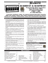
To configure the meter’s programming codes,
the meter uses the three right-hand side dis-
play digits. These are known as the 1st, 2nd,
and 3rd digits and can be seen in the diagram
opposite.
Prog.
SP1 SP2 SP4SP3 SP5 SP6
Operational Display
1st
Digit
2nd
Digit
3rd
Digit
The logic diagram on Page 4 shows the code
structure of the Tiger 320 Series meter range.
Also, the difference between the E and T
version of the Tiger range is described. The
diagrams on the following pages show the
three-digit settings available for each code.
Note:
All displays shown in this code
sheet are for a 5-digit, 7-seg-
ment display. 6 or 8-digit and
alphanumeric displays will be
slightly different.
Contents
Initial Setup Procedures.............................. 2
Tiger 320 Series Code Logic Diagram. . . . . . . . . . . . . . . . . . 4
CALIBRATION MODE............................... 5
CODE 1 ..........................................6
CODE 2 ..........................................7
CODES 3 to 5 .....................................8
CODES 6 to 9 .....................................9
CODE 10 ........................................10
SETPOINT PROGRAMMING MODE – SPC_1 to SPC_6. 11
Detailed Descriptions of Setpoints Functions. . . . . . . . . . . . 14
Customer Code Settings – Main Programming Mode. . . . . 15
Customer Code Settings – Setpoint Programming Mode. . 18
Commonly Used Registers . . . . . . . . . . . . . . . . . . . . . . . . . . 19
User Notes.......................................20
Note:
1. Use the button to step through
the codes of the Main or Setpoint
Programming Mode.
2. To save a Main Programming Mode
code setting and return directly to the
operational display, press the button
and then the buttons and at the
same time.
2. To save a Setpoint Programming
Mode code setting and return directly
to the operational display, press the
button and then the buttons and
at the same time.
4. When configuring the three-digit
code and setpoint settings, pressing
t h e and buttons at the same time
increases the display parameter in
increments of 100 counts.
P
P
P
P
P

Tiger 320 Series Programming Code Sheet
Code Version v3.09b
Texmate Inc. Tel. (760) 598 9899 • www.texmate.com 2
PCS v3.09b (NZ101)
Programming Tip
The Model and Software Code Version check-
ing procedure can be performed at any time
without interfering with other configuration
settings.
SP1 SP2 SP3 SP4 SP5 SP6
Prog.
SP1 SP2 SP3 SP4 SP5 SP6
Prog.
SP1 SP2 SP3 SP4 SP5 SP6
Prog.
SP1 SP2 SP3 SP4 SP5 SP6
Prog.
SP1 SP2 SP3 SP4 SP5 SP6
Prog.
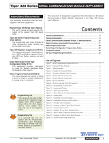
MODEL AND SOFTWARE CODE VERSION CHECK PROCEDURE
MODEL &
SOFTWARE
CODE VERSION
CHECK
Press
then
once
release
Press
and
hold
Step 1
Step 2
Step 3
The above displays toggles
three times before returning to
the operational display
SP1 SP2 SP3 SP4 SP5 SP6
Prog.
Operational Display
Operational Display
Example
Release
after
pressing
Prog.
Model
Number
Typical
Software
Version
Number
Press and hold
the and
buttons
While holding both
buttons, press the Prog.
button then release
all three buttons
START HERE
a
b
c
Model No: .............................................................................
Software Version No: ...................................................
Customer ID:......................................................................
Macro ID: ..............................................................................
Initial Setup Procedures
Model and Software Code Version Check
The meter model and software code version number can be
checked at any time while in the operational display using the
following procedure.
Before configuring the meter, carry out the following meter
configuration checks:
• Model and software code version check.
• Code blanking and macro check.
After powering-up the meter, check the model and software
code version number and note this below.

Tiger 320 Series Programming Code Sheet
Code Version v3.09b
Texmate Inc. Tel. (760) 598 9899 • www.texmate.com 3
PCS v3.09b (NZ101)
Prog.
SP1 SP2 SP4SP3 SP5 SP6
TEXMATE
Prog.
SP1 SP2 SP4
SP3
SP5 SP6
TEXMATE
Prog.
SP1 SP2 SP4SP3 SP5 SP6
TEXMATE
Press
and
hold
Step 1
Step 2
While holding both
buttons, press the Prog.
button.
Step 2
Step 3
Operational Display
Example
Release
after
pressing
Prog.
Code
Blanking
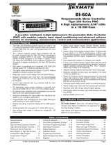
CODE BLANKING & MACRO CHECK PROCEDURE
Press and hold
the and
buttons
While holding both
buttons, press the Prog.
button.
Prog.
SP1 SP2 SP4
SP3
SP5 SP6
TEXMATE
Release the
the and
buttons and hold
the Prog. button
for approx. 1 sec
then release
Release
after 1
sec
Prog.
SP1 SP2 SP4SP3 SP5 SP6
TEXMATE
Step 4
Press the button to switch
code blanking oFF
Press
1
NOTE: Unless otherwise
requested, the factory
default setting is oFF
Code Blanking & Macro
Check Procedure
continued in (Step 5)
Programming Tip
Code Blanking and Macro ON/OFF settings
revert to the meter’s original configuration set-
tings when the meter is powered off and on.
Prog.
SP1 SP2 SP4SP3 SP5 SP6
TEXMATE
Operational Display
CODE BLANKING & MACRO CHECK PROCEDURE 1
Prog.
SP1 SP2 SP4
SP3
SP5 SP6
TEXMATE
Press
1
Step 7
Press the Prog. button.
continued from Step 4
Prog.
SP1 SP2 SP4
SP3
SP5 SP6
TEXMATE
Press
1
Prog.
SP1 SP2 SP4SP3 SP5 SP6
TEXMATE
Example Macro
Prog.
SP1 SP2 SP4SP3 SP5 SP6
TEXMATE
Step 6
Press the button to switch
the macro OFF
Press
1
NOTE: Unless otherwise
requested, the factory
default setting is on.
Step 5
Press the Prog. button.
Code Blanking and Macro Check
Tiger 320 Series meters have the ability to hide (blank out)
all or some programming codes, making them tamper-proof.
This can only be done using the Meter Configuration Utility
program.
With code blanking turned ON, all main and setpoint codes
that have been blanked out during factory programming are
hidden, preventing them from being reprogrammed. Any
codes that have not been blanked out are still visible and can
be reprogrammed.
Turning code blanking OFF means all meter programming
codes are visible when you enter the programming modes
and can be reprogrammed.
A macro is a set of commands that run automatically when
the meter is powered up. Texmate has a growing library of
macros to suit a wide range of standard customer applica-
tions.
Macros can be installed in the meter at the factory dur-
ing initial programming or by the customer at some later
date. Macros are written and compiled using the Tiger
Development System (TDS) compiler program, and loaded
into the meter using either the compiler program or the con-
figuration program.
Turning the macro OFF means that the meter will not perform
the automatic commands pre-programmed to run with the
macro.
Unless requested to blank out all or some programming
codes and/or run a macro, Texmate program the meter in the
code blanking OFF and macro ON (default) setting.
To turn the code blanking and macro settings from ON to
OFF carry out the following procedure:
START HERE
CODE BLANKING & MACRO CHECK PROCEDURE

Tiger 320 Series Programming Code Sheet
Code Version v3.09b
Texmate Inc. Tel. (760) 598 9899 • www.texmate.com 4
PCS v3.09b (NZ101)
Tiger 320 Series Code Logic Diagram
To enter press the
P
and
buttons at the same time
Calibration Modes for Input and Output
Code 1 – Display Configuration
Code 2 – CH1 Measurement Task & Sampling Rate
Code 3 – CH1 Post Processing & Serial Mode Functions
Code 4 – CH2 Measurement Task & 32-point Linearization
Code 5 – CH3 Functions
Code 6 – CH4 Functions
Code 7 – Result Processing
Code 8 – Data Logging & Print Mode
Code 9 – Functions for Digital Input Pins
[CAL]
[Cod_1]
[Cod_2]
[Cod_3]
[Cod_4]
[Cod_5]
[Cod_6]
[Cod_7]
[Cod_8]
[Cod_9]
To enter press the
P
and
buttons at the same time
Setpoint 1
[SP_1]
Setpoint Activation Values Mode
Setpoint 2
[SP_2]
Setpoint 3
[SP_3]
Setpoint 4
[SP_4]
Setpoint 5
[SP_5]
Setpoint 6
[SP_6]
Enter these menus to set setpoint
(SP) activation values
Setpoint 1
[SPC_1]
Setpoint & Relay Control Settings Mode
Setpoint 2
[SPC_2]
Setpoint 3
[SPC_3]
Setpoint 4
[SPC_4]
Setpoint 5
[SPC_5]
Setpoint 6
[SPC_6]
Enter these menus to configure SP control
settings
See Page 2 for code settings to calibrate the meter’s input and output signals.
See Page 3 for code settings to configure the setpoint annunciators and other
display functions.
See Page 4 for code settings to configure the CH1 measurement task and
sampling rate.
See Page 5 for code settings to configure CH1 post processing and serial
mode functions.
See Page 5 for code settings to configure the second channel (CH2) mea-
surement task and 32-point linearization settings when using dual input signal
conditioners.
See Page 5 for code settings to configure the third channel (CH3) when
using triple input signal conditioners.
See Page 6 for code settings to configure the fourth channel (CH4) when
using quad input signal conditioners.
See Page 6 for code settings to configure the meter for processing the result
of CH1 and CH2.
See Page 6 for code settings to configure data logging and data printing
using the meter.
See Page 6 for code settings to configure the meter for inputs from external
sources through the digital input pins.
The Setpoint and
Relay Control
Settings diagram
on Pages 8, 9, and
10 shows the three
digit configuration
settings that are
applied individually
to each setpoint.
Display Brightness
[bri]
Allows you to adjust the display brightness in a range of 8 settings. 0 being
dull, 7 being bright.
Code 10 – Bargraph Setup
[Cod10]
See Page 7 for code settings to configure the meter’s bargraph display.
Main Programming Mode Setpoint Programming Mode
P
P
P
P
P
P
P
P
P
P
P
P
P
P
P
P
P
P
P
P
P
P
P
Prog.
SP1 SP2 SP4SP3 SP5 SP6
Operational Display
Prog.
SP1 SP2 SP4SP3 SP5 SP6
Operational Display
P
Default setting = 18000
Default setting = –18000
Default setting = 5000
Default setting = –5000
Default setting = 10000
Default setting = –10000
Prog.
SP1 SP2 SP4SP3 SP5 SP6
Operational Display
Tiger 320 Series Programmable Meter Controllers (PMCs) come in
two versions: the economy E version, or the top-of-the-line T version.
The standard E version comes with 4 kilobits of EEPROM installed,
whereas the standard T version comes with 32 kilobits of EEPROM
Installed. Also, the T version can have a macro installed.
The standard 4-kilobit E version can be upgraded to 32 or to up to
1024 kilobits. The standard 32-kilobit T version can be upgraded to
1024 kilobits. The amount of EEPROM installed in the controller deter-
mines the range of functions it is capable of performing. The following
table lists the functions that require specific amounts of memory.
Version Functions
Memory
(kilobits)
Remarks
E 1 linearization table4 (standard) Table 1 is available to
be applied to chan-
nels 1 to 4 and result.
4 linearization tables32 Tables 1 to 4 are
available to be
applied to channels 1
and 2 and result.
Table 3 can be applied
to channel 3.
Table 4 can be applied
to channel 4.
All four tables can be
cascaded to form a
single 125-point lin-
earization table avail-
able to be applied to
channels 1 and 2 and
result.
Data loggingup to 1024 With up to 1024
kilobits installed,
the controller can
perform data logging
functions along with
complete linearization
functionality. With
a real-time clock
installed, date and
time stamps can be
included.
T 4 linearization tables32 (standard) As for E version with
32 kilobits installed.
Macro programming A macro can be pro-
grammed to suit a
user's logic control
application.
Data loggingup to 1024 As for E version with
up to 1024 kilobits
installed, but with
macro programming
functionality available.
E/T Versions of Tiger 320 Series Programmable Meter Controller

Tiger 320 Series Programming Code Sheet
Code Version v3.09b
Texmate Inc. Tel. (760) 598 9899 • www.texmate.com 5
PCS v3.09b (NZ101)
CALIBRATION MODE
0 Functions Activated
by Pressing the
PROGRAM Button
1 Calibration
Procedures
2 Related Calibration
Functions
3 -
CALIBRATION MODES FOR INPUT AND OUTPUT
0 No function
1 On Demand TARE from the PROGRAM button
2 On Demand Single-point Calibration from the
PROGRAM button (requires single input source)
3 On Demand Two-point Calibration from the
PROGRAM button (requires dual input source)
4 On Demand Primary Input Compensation Mode from the
PROGRAM button
5 On Demand Manual Loader Mode (no increase /
decrease with HOLD active)
6 -
7 -
Note:
When in the TARE mode, a decimal point appears at the right
of the display indicating that the tare value is NOT zero.
OBJECT FOR 2nd DIGIT
0 Result
1 Channel 1
2 Channel 2
3 Channel 3
4 Channel 4
FIRST DIGIT SECOND DIGIT THIRD DIGIT
0 Manual Calibration (requires NO input source)
1 T
wo-point Calibration (requires dual input source)
2 Calibrate Thermocouple (requires K type thermocouple
input source)
3 Calibrate RTD (requires RTD 385 input source)
4 -
5 Calibrate Analog Output mA/V (requires multimeter con-
nected to pins 16 and 17)
6 -
7 -
0 Serial Communications Properties
1 Set Auto Zero Maintenance for 3rd digit
2 Set Averaging Samples & Averaging Window for 3rd digit
3 Totalizer Settings Mode
4 Setup 32-point Linearization Tables
5 Scale Analog Output LOW/HIGH Display Readings
6 -
7 -
Use but-
tons to set SPAN
Use
buttons to set
OFFSET
Use buttons
to set ZERO
Use buttons to
set SCALE
Use buttons
to set SPAN
P
P
For detailed calibration procedures, see
Calibration Procedures Supplement
Press the PROGRAM button for 4 seconds to tare the selected channel
P
P
4 secs
P
4 secs
Use
buttons to set
ZERO
Use buttons to
set SPAN
P
4 secs
P
4 secs
P
P
Use buttons
to set baud rate
Use but-
tons to set parity
Use buttons to set
address from 1 to 255
Use buttons to set LOW
display reading [CAL_L]
Use buttons to set HIGH
display reading [CAL_h]
Use
to set CAL_L
Use buttons
to set CAL_h
Use buttons to
set time period
Use buttons to
set total from 1-65535
Select the method of configuring the user defined linearization
table: manual or auto setup mode. Then set the table number,
date, and serial number before setting the linearization points.
Or select [init] to re-initialize the default table settings.
P
P
P
P
P
P
Use buttons to set averaging
samples from 0 to 255 counts Use buttons to set averaging
window from 0 to 65535 counts
P
Use buttons
to set AZ_M from 0
to 255 counts
P
Auto zero capture band
For detailed calibration procedures, see
Calibration Procedures Supplement
Use buttons to ADJUST primary input compensa-
t i o n value from –19999 to 99999
Converting °F to °C
1) Calibrate the meter to suit the temperature sensor input. Use K type
thermocouple input for thermocouples. Use RTD 385 for RTDs.
2) To convert °F to °C enter the calibration mode and set [CAL] to [10X].
3) On a 5-digit meter set the scale factor to [0.5555] and the offset to
[–178] counts.
4) On a 6-digit meter set the scale factor to [0.55555] and the offset to
[–178] counts.
Ignore the decimal point on OFFSET settings
Use buttons to set
time delay in milliseconds
Except ASCII Mode which uses message terminators:
Use buttons to
set AZ_A from 0 to
65535 counts
0 -
1 Analog Output 1
2 Analog Output 2
0 -
1 Analog Output 1
2 Analog Output 2
THIRD DIGIT
THIRD DIGIT
P
Auto zero motion Auto zero aperture window
0 -
1 T
otal 1
2 T
otal 2
THIRD DIGIT
Note:
The input channel setting in
the 3rd digit is not relevant to
the manual setup mode.
0 -
1 CH1
2 CH2
3 CH3
THIRD DIGIT
0 -
1 CH1
2 CH2
3 CH3
4 CH4
THIRD DIGIT
Use buttons to ADJUST analog output 1 or 2 value
from –19999 to 99999 via the manual loader output
Default setting 10,000 counts
P
P
Use buttons
to set to 7 or 8 bits
P
0 -
1 CH1
2 CH2
3 CH3
4 CH4
THIRD DIGIT
Use buttons
to set Cutoff from
–19999 to 32767
P
Use buttons to set
rollover to ON or OFF
If Code 3 set to Master
Mode [XX2] ONLY $ = minimum 50 ms delay
* = minimum 2 ms delay
Use buttons
to set input rate
Note:
The correct input signal channel must be
selected in the 3rd digit when configuring a
linearization table using the auto setup mode.
Use buttons to set
AZ_C from 1 to 254 counts
Rate-of-change in counts/second
This is the default 3rd digit box. If not pointing to another 3rd digit box, all 2nd digit settings should be regarded as pointing to here.

Tiger 320 Series Programming Code Sheet
Code Version v3.09b
Texmate Inc. Tel. (760) 598 9899 • www.texmate.com 6
PCS v3.09b (NZ101)
CODE 1
DISPLAY FUNCTIONS
0 Normal Display Mode (i.e. operational display
shows selected register)(updates every 0.5
seconds)
1 Manual Loader Mode (Direct display). See Note*
2 Update at controlled output rate selected in Code 2
3 -
4 -
5 Select data source as per 3rd digit. See Note 4
6 Select display format as per 3rd digit. See Note 4
7 Select text character as per 3rd digit. See Note 4
SELECT DATA SOURCE FOR
0 Primary Display
1 Second Display. See Note 2
2 Third Display. See Note 2
3 Peak/Valley
4 Analog Output 1
5 Analog Output 2 (under development)
6 T
otalizer 1
7 Totalizer 2
CODE 1 – DISPLAY CONFIGURATION
LAST DIGIT ROUNDING
0 No rounding
1 Rounding by 2’s
2 Rounding by 5’s
3 Rounding by 10’s
DISPLAY UNITS
0 Decimal
1 24-hour clock mode
Hours: Minutes:Seconds (6-digit version only)
2 12-hour clock mode (12:30 am is displayed as
12:30A. 12:30 pm is displayed as 12:30P)
3 24-hour clock mode
Days: Hours:Minutes (6-digit version only)
4 -
5 -
6 -
7 Octal
DECIMAL POINT PLACEMENT
0 No decimal point
1 XX.XX.XX (6 or 8-digit version only)
2 X.XXXXX (6 or 8-digit version
only)
3 X.XXXX
4 X.XXX
5 X.XX
6 X.X
7 Decimal Point set from the rear
(X.XXXXX to XXXXXX). See Note
3.
Also See Note 4
DISPLAY FORMAT MODE
0 Result
1 Channel 1
2 Channel 2
3 Channel 3
4 Channel 4
5 Default Display
6 T
otal 1
7 T
otal 2
0 Result
1 Channel 1
2 Channel 2
3 Channel 3
4 Channel 4
5 Default Display
6 T
otal 1
7 T
otal 2
SELECT DISPLAY FORMAT FOR
SELECT TEXT CHARACTER FOR
SECOND DIGIT THIRD DIGIT
Note 1:
LED annunciators are always off, except when the meter is in single channel
VOLTAGE or CURRENT mode and Code 3 = [X6X], or Code 7 = [X6X] in
which case the LEDs indicate which 32-point table has been selected from
the rear pins (SP1 = Table 1, SP2 = Table 2, SP3 = Table 3, SP4 = Table 4).
Note 2:
These options are only for use with meters that have more than one display.
With bargraph meters the PRIMARY display is the digital display, and the
SECONDARY display is the bargraph display.
Note 3:
These functions are only available on selected input modules.
Note 4:
If Code 1's display modes have been entered (second digit set to 5, 6, or
7), the display will cycle between Code 1 and the display functions mode
each time the PROGRAM button is pressed. To leave the cycle, the Code
1 digits must be reset to any relevant function between [X00] to [X20]. This
takes you into Code 2.
Select Data Source
Select Last Digit Text Character
P
FIRST DIGIT SECOND DIGIT THIRD DIGIT
Program the three digits to the required display function mode
Note*:
For the Manual Loader Mode (Direct Display) to work, with Code 1 set to
[X54] the data source for the analog output (1 or 2) must be set to [diSP].
Operating range upper and lower limits can be set for the manual loader
mode.
The setpoint activation values for setpoint 5 becomes the upper limit and
setpoint 6 becomes the lower limit.
When either the direct display or on demand manual loader mode is
programmed into the meter, the values for setpoint 5 and setpoint 6 are
activated as upper and lower limits.
See Analog Output Supplement for further details.
Note 5:
If only 4 kB memory installed, functions 2 to 6 are not available in:
• Code 3 second digit.
• Code 4 third digit.
• Code 7 second digit.
Note 6:
These functions are not available on all models and in some cases require
additional hardware.
Note 7:
For future development.
Note:
Selecting 1, 2, or 3 in the 2nd
digit of this mode configures
the display of the selected
channel as a clock.
Use the button to cycle through the
menu, and the button to cycle back.
Use the buttons to
select a register as the
data source
Use the button to cycle through the
menu, and the button to cycle back.
FRONT PANEL ANNUNCIATORS
0 ON when Setpoints are ON
(relay engaged)
1 ON when Setpoints are OFF
(relay de-engaged)
2 Always OFF. See Note 1.
3 LED SP1 ON indicates RISING
signal trend.
LED SP2 ON indicates RISING
signal trend.
FIRST DIGIT

Tiger 320 Series Programming Code Sheet
Code Version v3.09b
Texmate Inc. Tel. (760) 598 9899 • www.texmate.com 7
PCS v3.09b (NZ101)
FOR VOLTAGE
0 No function
1 Peak detector
2 Pressure with Auto-cal
FOR THERMOCOUPLE
0 Type J
1 Type K
2 Type R
3 Type S
4 Type T
5 Type B
6 Type N
7 For sensor tables other than those listed above
contact Texmate
FOR RTD TYPE (2-, 3-, 4- WIRE)
0 Resistance
1 Pt 385 100 Ω RTD
2 Pt 392 100 Ω RTD
3 Zn 120 Ω RTD
4 Cu 10 Ω RTD
FREQUENCY RANGE SELECTION
0 99.999 Hz range from 0.010 Hz
1 99.999 Hz range from 2.000 Hz
2 999.99 Hz range from 0.01 Hz
3 999.99 Hz range from 2.00 Hz
4 9999.9 Hz range from 0.1 Hz
5 9999.9 Hz range from 2.0 Hz
6 99 kHz range from 1 Hz (1 s gate)
7 655.35 kHz range from 10 Hz (0.1 s gate)
PERIOD MEASUREMENT SELECTION
0 99.999 s
1 9.9999 s
2 999.99 ms
3 99.999 ms
COUNTER/RESIDENT TIMER/CLOCK SELECTION
0 Counter input with 16-bit Pre-scaler
1 Setting of 16-bit Pre-scaler
2 Debounced Counter with Pre-scaler
3 Up/Down Counter with Pre-scaler
4 0.1 sec Timer with Pre-scaler
5 –
6 External 24-hour clock
7 Internal 24-hour clock
ANALOG SAMPLE AND OUTPUT RATE
0 Sample Rate:
Typically 10 samples/second (60 Hz)
Control Output Rate:
0.1 seconds
See Example
1 Sample Rate:
Typically 10 samples/second (50 Hz).
Control Output Rate:
0.1 seconds
See Example
2 Sample Rate:
Typically 10 samples/second (60 Hz)
Control Output Rate:
Counter or 10 millisecs Control Output Rate
See Example
3 Sample Rate:
Typically 10 samples/second (50 Hz)
Control Output Rate:
Counter or 10 millisecs Control Output Rate
See Example
Note:
Output Rate refers to setpoint and macro outputs, and input
rates from smart input modules.
Note:
All above sample rates are quoted for single channel operation.
Where more than one channel is available, sample rates are
divided by the number of active channels. See Example.
MEASUREMENT TASK
0 Voltage, Current
1 TC (3rd digit selects type of TC)
2 RTD/Resistance 3-wire (3rd digit selects type of RTD)
3 RTD/Resistance 2- or 4-wire (3rd digit selects type of RTD)
4 Frequency
5 Period
6 Counter
7 Smart Input Module
CODE 2 – CHANNEL 1 MEASUREMENT TASK AND SAMPLING RATE
SMART INPUT MODULE
0 Output Register 1
1 Output Register 2
2 Output Register 3
3 Output Register 4
4 Output Register 5
5 Output Register 6
6 Output Register 7
7 Smart Input Module Register 1 Code Setup.
See Note 7.
THIRD DIGIT
FIRST DIGIT SECOND DIGIT
CODE 2
1 Channel = 10 samples/second
2 Channels = 5 samples/second
3 Channels = 3.33 samples/second
4 Channels = 2.5 samples/second
Example: 10 Samples/Second
Note 7:
Only available with selected
input modules.
1 = 0.1 second
10 = 1 second
600 = 1 minute
3600 = 1 Hour***
X61 Selects Prescaler
Use but-
tons to set pres-
cale values
P
Press
Use the buttons to set the
required smart input module code
(0 to 377). See I-Series Input
Module Supplement for code
details.
***Note:
For the 1 hour setting, the
scale factor for CH1 must be
set to 0.1 in the calibration
mode setting [111].

Tiger 320 Series Programming Code Sheet
Code Version v3.09b
Texmate Inc. Tel. (760) 598 9899 • www.texmate.com 8
PCS v3.09b (NZ101)
CODES 3 to 5
FIRST DIGIT SECOND DIGIT THIRD DIGIT
CHANNEL 1 POST PROCESSING
0 Direct Display of Input (no pro-
cessing)
1 Square Root of Channel 1
2 Inverse of Channel 1
3 –
32-POINT LINEARIZATION FOR CHANNEL 1
0 No Linearization on CH1
1 32-point Linearization on CH1 using Table 1
2 32-point Linearization on CH1 using Table 2.
See Note 5
3 32-point Linearization on CH1 using Table 3.
See Note 5
4 32-point Linearization on CH1 using Table 4.
See Note 5
5 125-point Linearization on CH1 (Tables 1 to 4
cascaded). See Note 5
6 32-point Linearization on CH1 (Tables 1 to 4
selected from the rear pins of selected input
modules).
The selected table is not available if CH2, CH3,
or CH4 is operating in the analog output mode.
CH1 must be set to Voltage, Current in Code 2
[X0X]. See Note 5
7 -
Note:
All linearization tables are set up in the
Calibration Mode [24X].
SERIAL MODE
0 ASCII Mode
1 Modbus Mode
2 Master mode (used to customize
print mode protocols via macro)
3 Print Mode
4 Ethernet Mode. See Note 6
5 Devicenet Mode (requires
Devicenet hardware module).
See Note 6
CODE 3 – CHANNEL 1 FUNCTIONS (POST PROCESSING & SERIAL MODE)
MEASUREMENT TASK
0 Voltage, Current
1 TC (type as per 2nd digit)
2 RTD/Resistance
(type as per 2nd digit)
3 Second Digital Input Channel
(type as per 2nd digit)
FOR VOLTAGE & CURRENT
0 Channel 2 Disabled
1 Direct (no post processing)
2 Square Root of Channel 2
3 Inverse of Channel 2
4 Output Register 1 (smart module)*
5 Output Register 2 (smart module)*
6 Output Register 3 (smart module)*
7 Output Register 4 (smart module)*
32-POINT LINEARIZATION FOR CH2
0 No user defined Linearization
on CH2
1 32-point Linearization on CH2
using Table 1
2 32-point Linearization on CH2
using Table 2. See Note 5
3 32-point Linearization on CH2
using Table 3. See Note 5
4 32-point Linearization on CH2
using Table 4. See Note 5
5 125-point Linearization on CH2
(Tables 1 to 4 cascaded). See
Note 5
6 –
7 –
CODE 4 – CHANNEL 2 MEASUREMENT TASK AND 32-POINT LINEARIZATION
FOR THERMOCOUPLE
0 Type J
1 T
ype K
2 T
ype R
3 T
ype S
4 T
ype T
5 Type B
6 T
ype N
7 For sensor tables other than those
listed above contact Texmate
FOR RTD TYPE (3-WIRE)
0 Resistance
1 Pt 385 100 Ω RTD
2 Pt 392 100 Ω RTD
3 Zn 120 Ω RTD
4 Cu 10 Ω RTD
DIGITAL INPUT
0 Frequency - 99.999 Hz range from
0.001 Hz
1 Frequency - 999.99 Hz range from 0.01 Hz
2 Frequency - 99.999 kHz range from 1 Hz
(1 s gate)
3 Frequency - 500 kHz range from 10 Hz
(0.1 s gate)
4 Period - 9.9999 s (100 µs resolution)
5 Period - 999.99 ms (10 µs resolution)
6 Up/Down Counter with Prescaler
7 Set Prescaler
FOR THERMOCOUPLE
0 Type J
1 T
ype K
2 T
ype R
3 T
ype S
4 T
ype T
5 Type B
6 T
ype N
7 For sensor tables other than those
listed above contact Texmate
FOR RTD TYPE (2-, 3-, 4- WIRE)
0 Resistance
1 Pt 385 100 Ω RTD
2 Pt 392 100 Ω RTD
3 Zn 120 Ω RTD
4 Cu 10 Ω RTD
MEASUREMENT TASK
0 Ch 3 Disabled
1 Voltage, current
2 TC (3rd digit selects type of TC)
3 RTD/Resistance (3rd digit selects type of RTD)
4 Real Time Clock & Timer (3rd digit selects type)
5 -
6 -
7 Smart Input Module (3rd digit selects register)
CODE 5 – CHANNEL 3 FUNCTIONS
FIRST DIGIT SECOND DIGIT THIRD DIGIT
CH3 POST PROCESSING
0 Direct Display of Input
(no processing)
1 Square Root of
Channel 3
2 Inverse of Channel 3
3 4 kilobits Meters
NO Linearization
32 kilobits Meters
32-point Linearization
of CH3 using Table 3
Note:
All linearization
tables are set up in
the Calibration Mode
[24X].
FOR REAL-TIME CLOCK & TIMER
0 HRS:MIN:SEC
1 HRS:MIN
2 -
3 -
4 1 Second Count UP Timer
5 1 Second Count DOWN Timer
6 -
7 -
FOR SMART INPUT MODULE
0 Output Register 1
1 Output Register 2
2 Output Register 3
3 Output Register 4
4 Output Register 5
5 Output Register 6
6 Output Register 7
7 Smart Input Module Register 2
Code Setup
P
Press
Use the buttons to set the
required smart input module code
(0 to 377). See I-Series Input
Module Supplement for code
details.
Note 6:
These functions are not available
on all models and in some cases
require additional hardware.
Note 5:
If only 4 kilobits of memory is installed,
only Table 1 is available for:
• CH1 in Code 3, 2nd digit.
• CH2 in Code 4, 3rd digit.
• CH3 in Code 5, 1st digit.
• CH4 in Code 6, 1st digit.
• RESULT in Code 7, 2nd digit.
Note:
The function of the out-
put register selected
varies according to the
input module installed.
*Note:
Selecting 040 to 070 in the 2nd digit of Code 4 selects
one of the following settings in the installed smart input
module’s output register map:
Note:
The register map is different for each smart input
module. See installed input module data sheet for
specific smart register 1 function map.
4 selects
5 selects
6 selects
7 selects
2nd Digit Input module’s output register map
0
1
2
3
1 = 0.1 second
10 = 1 second
600 = 1 minute
3600 = 1 Hour***
X61 Selects Prescaler
Use but-
tons to set pres-
cale values
***Note:
For the 1 hour setting, the
scale factor for CH1 must be
set to 0.1 in the calibration
mode setting [111].

Tiger 320 Series Programming Code Sheet
Code Version v3.09b
Texmate Inc. Tel. (760) 598 9899 • www.texmate.com 9
PCS v3.09b (NZ101)
CODES 6 to 9
CH4 POST PROCESSING
0 Direct Display of Input (no pro-
cessing)
1 Square Root of Channel 4
2 Inverse of Channel 4
3 4 kilobits Meters
NO Linearization
32 kilobits Meters
32-point Linearization of CH4 using
Table 4
Note:
All linearization tables are set up
in the Calibration Mode [24X].
CODE 6 – CHANNEL 4 FUNCTIONS
FIRST DIGIT SECOND DIGIT THIRD DIGIT
FOR THERMOCOUPLE
0 Type J
1 T
ype K
2 T
ype R
3 T
ype S
4 T
ype T
5 Type B
6 T
ype N
7 For sensor tables other than those
listed above contact Texmate
FOR RTD TYPE (2-, 3-, 4- WIRE)
0 Resistance
1 Pt 385 100 Ω RTD
2 Pt 392 100 Ω RTD
3 Zn 120 Ω RTD
4 Cu 10 Ω RTD
MEASUREMENT TASK
0 No Function
1 Voltage, Current
2 TC
(3rd digit selects type of TC).
See Note 7
3 RTD/Resistance
(3rd digit selects type of RTD).
4 Real Time Clock and Timer
(3rd digit selects type)
5 -
6 -
7 Smart Input Module
(3rd digit selects register)
FOR SMART INPUT MODULE
0 Output Register 1
1 Output Register 2
2 Output Register 3
3 Output Register 4
4 Output Register 5
5 Output Register 6
6 Output Register 7
7 Smart Input Module Register 3
Code Setup
RESULT PROCESSING
0 Direct Display of Result
as per processing per-
formed in 2nd and 3rd
digits
1 Square Root of Result
2 Inverse of Result
3 -
32-POINT LINEARIZATION FOR RESULT
0 No Linearization on Result
1 32-point Linearization on Result using Table 1
2 32-point Linearization on Result using Table 2. See Note 5
3 32-point Linearization on Result using Table 3. See Note 5
4 32-point Linearization on Result using Table 4. See Note 5
5 125-point Linearization on Result (Tables 1 to 4 cascaded).
See Note 5
6 32-point Linearization on Result (Tables 1 to 4 selected
from the rear of the meter).
The selected table is not available if CH2, CH3, or CH4 is
operating in the analog mode. CH1 must be set to Voltage,
Current in Code 2 [X0X].
See Note 5
7 –
MATHS FUNCTIONS FOR RESULT
0 Result Register not Updated
1 pH Meter (CH1 = Tbuff, CH2 =
pH)
2 Result = CH1, Setpoint 2 = CH2
3 Result = CH1 + CH2
4 Result = CH1 - CH2
5 Result = CH1 x CH2/10 000
6 Result = (CH1 x 20 000)/CH2
7 Result = CH1
CODE 7 – RESULT PROCESSING
CODE 8 – DATA LOGGING AND PRINT MODE OPTIONS
FIRST DIGIT SECOND DIGIT THIRD DIGIT
DATA LOG BUFFER TYPE
0 No Data Logging
1 Cyclic Buffer
2 Linear FIFO Buffer.
3 Reset Buffer Number to 0.
Note:
Setting Code 8 to [3XX] resets the
data log buffer to 0. Once reset,
Code 8 must be set back to the
required data log buffer setting.
DATE & TIME STAMP OPTIONS
0 Printer Format – No time stamp with print/
log
1 Printer Format – Time stamp format 1 [Mth-
Day-Yr Hrs:Min:Sec] (with <CR><LF>)
2 Printer Format – Time stamp format 2 [Day-
Mth-Yr Hrs:Min:Sec] (with <CR><LF>)
3 Printer Format – Time stamp format 3 [Hrs:Min:
Sec] (with <CR><LF>)
4 Spreadsheet Format – No time stamp with
print/log
5 Spreadsheet Format – Time stamp format 1
[Mth-Day-Yr Hrs:Min:Sec]
6 Spreadsheet Format – Time stamp format 2
[Day-Mth-Yr Hrs:Min:Sec]
7 Spreadsheet Format – Time stamp format 3
[Hrs:Min:Sec]
ALL ABOVE ARE REAL-TIME CLOCK OPTIONS
LOG OR PRINT TRIGGER
0 No trigger
1 Trigger on Demand from
PROGRAM Button
2 Trigger on Demand from F1 Button
3 T
rigger on Demand from F2 Button
4 T
rigger on Demand from HOLD Pin
5 T
rigger on Demand from LOCK Pin
6 -
7 -
Note:
Log and/or Print will only trigger
if enabled.
DISPLAY TEST PIN
0 Display test only
1 Reset Counter Channel 1 and total
2 at Power-up
2 Reset Counters Channel 1, 2, 3, 4,
Total 1, and Total 2 at Power-up
3 Reset Total 1, and Total 2 at Power -up
HOLD PIN
0 Display Hold
1 Reset Channel 1
2 Reset Total 1 and Total 2
3 Reset Total 2
4 Reset Peak, Valley
5 Clear Tare
6 Set Tare
7 Unlatch (de-energize) all Setpoints
LOCK PIN
0 Key Lock
1 Reset Channel 1
2 Reset Channel 2
3 Reset Channel 3
4 Reset Channel 4
5 Clear Tare
6 Reset Total 1
7 Unlatch (de-energize) all Setpoints
CODE 9 – FUNCTIONS FOR DIGITAL INPUT PINS
FOR REAL-TIME CLOCK & TIMER
0 HRS:MIN:SEC
1 HRS:MIN
2 -
3 -
4 1 Second Count UP Timer
5 1 Second Count DOWN Timer
6 -
7 -
Note 7:
For future development.
P
Press
Use the buttons to set the
required smart input module code
(0 to 377). See I-Series Input
Module Supplement for code
details.
Note 5:
If only 4 kilobits of memory is installed,
only Table 1 is available for:
• CH1 in Code 3, 2nd digit.
• CH2 in Code 4, 3rd digit.
• CH3 in Code 5, 1st digit.
• CH4 in Code 6, 1st digit.
• RESULT in Code 7, 2nd digit.
Note:
The function of the out-
put register selected
varies according to the
input module installed.

Tiger 320 Series Programming Code Sheet
Code Version v3.09b
Texmate Inc. Tel. (760) 598 9899 • www.texmate.com 10
PCS v3.09b (NZ101)
CODE 10
Logarithmic Bargraph Scaling
In all logarithmic scales a reference level is
required that is the level at 0 dB.
For example, in an RF measurement 0 dBm is at
a reference of 1 mW.
The scale is calculated from:
If the meter is scaled so that:
1 mW = 100 counts and 1 W = 100,000 counts
Then the reference for 0 dBm would be set to
100 counts:
BARGRAPH DISPLAY SETTINGS
0 No Function
1 Disable Overrange Flashing
2 Set up Colors
3 Set up Bar Scaling
BARGRAPH DISPLAY FORMAT BARGRAPH TYPE
0 Linear
1 Via linearization Table 1
2 –
3 Log – 10 Bar/Decade
4 Log – 20 Bar/Decade
5 Log – 25 Bar/Decade
6 Log – 33 Bar/Decade
7 Log – 50 Bar/Decade
CODE 10 – BARGRAPH SETUP
0 Setpoints on Bar
1 Peak, Valley on Bar
2 -
3 -
4 Min/Max with setpoints (low end of bar =
VALLEY, high end of bar = PEAK)
5 -
6 -
7 Bar Only (no setpoints on the bar)
Note:
Code 10 is only available with bar-
graph versions of the meter.
Note:
Data source for the bargraph is set
up in Code 1 [X51].
P
P
P
P
P
P
P
The bargraph colors are not applied to specific setpoints.
They are applied to whichever setpoint is configured at the
lowest setting and then to each next highest setpoint in turn.
If all six setpoints are used the colors are set as follows:
Color 1 Color BELOW lowest setpoint
This is the bargraph color before it reach-
es a setpoint.
Color 2 Color ABOVE lowest setpoint
Color 3 Color ABOVE next highest setpoint
Color 4 Color ABOVE next highest setpoint
Color 5 Color ABOVE next highest setpoint
Color 6 Color ABOVE next highest setpoint
Color 7 Color ABOVE highest setpoint
Set Up Bargraph Colors
P
Set Up Scaling for Linear Bargraph
OR
P
P
Bar Low Bar High Bar Nominal
P
Set Up Scaling for Logarithmic Bargraph
OR
P
Reference Bar Nominal
OR
OR
OR
FIRST DIGIT SECOND DIGIT THIRD DIGIT
Pressing the
buttons at the same
time returns to [oFF]
Bar Nominal
Bar Nominal sets the point on the bargraph at which the bar
begins to light up. This can be any position between and
including the bar low and bar high settings.
If bar nominal is set to the bar low setting, the bargraph
behaves like a typical bargraph making the segments light up
from the bottom of the bar and grow towards the top.
If bar nominal is set to the bar high setting, this makes all
segments from the displayed signal to the top of the bar
light up. As the signal increases, the number of lit segments
between the signal and the bar high setting becomes steadily
less. When the signal reaches the bar high setting no seg-
ments are lit.
Setting bar nominal to the midpoint between bar low and bar
high makes the bargraph behave like a typical center zero
bargraph. This means the bargraph lights up at the center of
the bar and moves either up or down the bar depending on
the displayed signal.
An added feature of this bargraph is that it can also be non-
symmetrical. This means that the bar nominal setting does not
need to be set at the mid-point between bar low and bar high.
For example, if the bargraph is configured to display –200 to
800 °C, bar low is set to –200 counts and bar high is set to 800
counts. Bar nominal is set to 0 counts. If a signal of –50 °C is
applied, the bar lights from 0 down to –50. If a signal of 600 °C
is applied, the bar lights from 0 up to 600.
For example, if the meter's full scale range is 20,000 counts,
the midpoint is 10,000 counts. If a signal of 10,000 counts is
applied, only one segment at the 10,000 count mark lights up.
If a signal of 17,000 counts is applied, the segments between
the center segment (10,000 counts) and the 17,000 count
mark light up.
If a signal of 5000 counts is applied, the segments between
the center segment (10,000 counts) and the 5000 count
mark light up.
10 log10
(input)
100= 0 dBm
Decade
(Counts)
–20
–10
0
10
20
30
40
1
10
100
1000
10,000
100,000
1,000,000
10 log10
counts (input)
reference
dBm
Now every 10 dBm represents a decade, the bargraph
can be scaled to a different amount of bars per decade
(as set in the 3rd digit).
See Example of Bars per Decade diagram opposite.
Reference. This is the number of counts
displayed for a 0 dB reference.
Bar Nominal. See Bar Nominal descrip-
tion above.
100 dBm
80 dBm
60 dBm
40 dBm
20 dBm
0 dBm
10 Bars/Decade
90 dBm
70 dBm
50 dBm
30 dBm
10 dBm
40 dBm
20 dBm
0 dBm
20 Bars/Decade
50 dBm
30 dBm
10 dBm
40 dBm
0 dBm
25 Bars/Decade
30 dBm
20 dBm
10 dBm
0 dBm
33 Bars/Decade
30 dBm
20 dBm
10 dBm
0 dBm
50 Bars/Decade
20 dBm
10 dBm
100
1000
10,000
100,000
1,000,000
100
1000
10,000
100,000
1,000,000
100
1000
10,000
100,000
1,000,000
100
1000
10,000
100,000
100
1000
10,000
Example of Bars per Decade

Tiger 320 Series Programming Code Sheet
Code Version v3.09b
Texmate Inc. Tel. (760) 598 9899 • www.texmate.com 11
PCS v3.09b (NZ101)
SETPOINT PROGRAMMING MODE – SPC_1 to SPC_6
Follow These Steps
The following procedures are written for SP1, all other setpoints are
configured in a similar manner.
1) Press the
P
and buttons at the same time. This enters the
setpoint programming mode. The display toggles between
[SP_1] and [18000].
This is SP1 of the Setpoint Activation Values Mode. Use the
and buttons to set SP1 or the
P
button to move to the
required setpoint.
2) After all required setpoint activation values have been set, press
the
P
button until [SPC_1] appears. This is the Setpoint & Relay
Control Settings Mode.
SPC_1 is the setpoint and relay control settings programming
menu for SP1. Set the three digits according to the codes in the
Setpoint and Relay Control Function Settings opposite in the fol-
lowing order:
Third Digit – Setpoint Delay Mode
Set to [XX5] and program the hysteresis, deviation, or PID
functions as required for SP1.
Reset back to [XX0].
Third Digit – Setpoint Timer Mode
Set to [XX6] and program the timer mode functions as
required for SP1.
Reset back to [XX0].
Third Digit – Setpoint Reset & Trigger Functions
Set to [XX7] and program the reset and trigger functions as
required for SP1.
Reset back to [XX0].
Second Digit – Setpoint Activation Source Mode
Set to [X1X] to select the setpoint activation source for SP1
from any channel or selected register shown above. Reset
back to [X0X].
If the SP source is from an external digital input, set to one of
either [X2X] to [X7X] to select the setpoint activation source
from one of six digital inputs (2 to 7). See *Note at 2nd digit.
First Digit – Relay Energize Mode
Select the relay energize mode for SP1 from 0 to 3.
Third Digit – Relay Latching & Manual Reset Functions
Program the third digit setpoint relay latching and manual
reset functions between 0 to 4 as required.
3) Press the
P
button to move to move to [SPC_2].
4) Repeat Step 2 for all required setpoints.
Setpoint Setup Sequence
0 No Latching
1 Relay Latched
2 Manual Relay Reset
3 Relay Latched and Manual Relay
Reset
4 Relay Latched Off
5 Hysteresis, Deviation & PID Mode
(includes SP Tracking)
6 Timer Modes:
•
OFF
.
•
Normal Delay.
• Repeat ON.
•
Pulse ON.
•
1-Shot ON.
•
Repeat OFF.
•
Pulse OFF.
• 1-Shot OFF.
Note:
In PID Mode, all Timer Modes on
SP1 set in [XX6} are not functional.
7 Advanced Functions Mode:
•
OFF
.
• Reset Trigger.
•
Reset Destination.
•
Reset Mode.
•
Reset Constant.
•
T
rigger Print from SP.
• Trigger Log from SP.
Note:
[XX5], [XX6], and [XX7] are set up
procedures only. To finish, reset to
0-4 as required for setpoint latching
and relay reset modes.
Relay Energize Function
0 Energizes ABOVE setpoint value
HYSTERESIS selected – relay energizes AT OR ABOVE setpoint
value plus hysteresis counts. De-energizes BELOW setpoint value
minus hysteresis counts.
Note:
If hysteresis set with ZERO counts, relay energizes AT OR ABOVE
the setpoint value.
DEVIATION selected – relay energizes INSIDE deviation band
(setpoint ± deviation counts). De-energizes OUTSIDE deviation band
(setpoint ± deviation counts).
PID selected – controls ABOVE setpoint value.
1 Energizes BELOW setpoint value
HYSTERESIS selected – relay energizes BELOW setpoint value
minus hysteresis counts. De-energizes AT OR ABOVE setpoint value
plus hysteresis counts.
Note:
If hysteresis set with ZERO counts, relay energizes BELOW the
setpoint value.
DEVIATION selected – relay energized OUTSIDE deviation band
(setpoint ± deviation counts). De-energized INSIDE deviation band
(setpoint ± deviation counts).
PID selected – controls BELOW setpoint value.
2 Energizes AT OR ABOVE setpoint value with FALLING INPUT
SIGNAL INITIAL START-UP INHIBIT
HYSTERESIS selected – relay energizes AT OR ABOVE set-
point value plus hysteresis counts with FALLING INPUT SIGNAL
INITIAL START-UP INHIBIT. De-energizes BELOW setpoint
value minus hysteresis counts with FALLING INPUT SIGNAL
INITIAL START-UP INHIBIT.
Note:
If hysteresis set with ZERO counts, relay energizes AT OR ABOVE
the setpoint value.
DEVIATION selected – relay energizes INSIDE deviation band
(setpoint ± deviation counts) with FALLING INPUT SIGNAL
INITIAL START-UP INHIBIT. De-energizes OUTSIDE deviation
band (setpoint ± deviation counts) with FALLING INPUT SIGNAL
INITIAL START-UP INHIBIT.
PID selected – controls ABOVE setpoint value.
3 Energizes BELOW setpoint value with RISING INPUT SIGNAL
INITIAL START-UP INHIBIT
HYSTERESIS selected – relay energizes BELOW setpoint value
plus hysteresis counts with RISING INPUT SIGNAL INITIAL START-
UP INHIBIT. De-energizes BELOW setpoint value minus hysteresis
counts with RISING INPUT SIGNAL INITIAL START-UP INHIBIT.
Note:
If hysteresis set with ZERO counts, relay energizes BELOW the
setpoint value.
DEVIATION selected – relay energizes OUTSIDE deviation
band (setpoint ± deviation counts) with RISING INPUT SIGNAL
INITIAL START-UP INHIBIT. De-energizes INSIDE deviation
band (setpoint ± deviation counts) with RISING INPUT SIGNAL
INITIAL START-UP INHIBIT.
PID selected – controls BELOW setpoint value.
SP Activation Source
0 Activate Setpoint Source from
Selected Register
1 Select Source for Setpoint
Note:
[X1X] is a register selection procedure
only. To finish, reset to [X0X] to activate
the selection, or reset to 2-7 as required
for digital input selection.
2 Digital Input – Capture Pin
3 Digital Input – D1 (selected input modules)
4 Digital Input – D2 (selected input modules)
5 Digital Input – D3 (selected input modules)
6 HOLD Pin
7 LOCK Pin
*Note:
If the setpoint source is set to [oFF]
or a digital input, the setpoint activation
value will have no effect and will not be
displayed.
SP Functions
FIRST DIGIT SECOND DIGIT THIRD DIGIT
SETPOINT AND RELAY CONTROL FUNCTION SETTINGS
Select Source for Setpoint Functions
Go to
Page 12
Go to
Page 12
Go to
Page 13
Use the buttons to
select a register as the
data source fro setpoint
Use the buttons to
cycle through the menu

Tiger 320 Series Programming Code Sheet
Code Version v3.09b
Texmate Inc. Tel. (760) 598 9899 • www.texmate.com 12
PCS v3.09b (NZ101)
P
X
X
PP
PXX XX
PP
PXX
PPP
PXX
PPP
PXX
PP
PXX
PPP
PXX
PPP
PXX
P
P
P
Set Deviation from 1 to
65535 counts. Selected
counts apply + and – from
setpoint value
P
P
P
P
P
P
Set the Span Set the Proportional Band Value Set the Integral Value Set the Derivative Value Set the Anti-reset Wind-up % PB Set the Minimum Cycle Time
PID FROM SETPOINT
1 AND 2 ONLY
MIN 0%
MAX 999.9%
MIN 0
MAX 99999
MIN 0
MAX 6553.5
MIN 0
MAX 999.9
MIN 0.1%
MAX 100.0%
MIN 0 secs
MAX 1000.0 secs
Select Tracking Setting
to
P
Select Flash Setting OFF or ON
P
OFF= Tracking Off
1 = SPX tracks SP1
2 = SPX tracks SP2
3 = SPX tracks SP3
4 = SPX tracks SP4
5 = SPX tracks SP5
6 = SPX tracks SP6
Set Hysteresis from 0 to
65535 counts. Selected
counts apply + and – from
setpoint value
Select Tracking Setting
to
P
From Page
11, third
digit [XX5]
From Page 11,
third digit [XX6]
Delay-on-make time (DOM)
0.1 to 6553.5 secs
Delay-on-break (DOB) time
0.1 to 6553.5 secs
Reset SPC_X to XX0
DOM 0.1 to 6553.5 secs Minimum on-time (M_on)
0.1 to 6553.5 secs
On-time (on_t) 0.1/0.001
to 6553.5/65.535 secs
DOM 0.1/0.001 to
6553.5/65.535 secs
On-time (on_t) 0.1/0.001 to
6553.5/65.535 secs
DOB 0.1 to 6553.5 secs
Off-time (oFF_t) 0.1/0.001 to
6553.5/65.535 secs
DOB 0.1/0.001 to 6553.5/65.535 secs
On_t 0.1/0.001 to 6553.5/65.535 secs
Off-time (oFF_t) 0.1/0.001
to 6553.5/65.535 secs
Off-time (oFF_t) 0.1/0.001
to 6553.5/65.535 secs
Minimum off-time (M_of)
0.1 to 6553.5 secs
Set Up Hysteresis, Deviation & PID Mode Settings
Set Up Timer Delay Settings
X
X
P
X
X
Reset SPC_X to XX0 Programming Tip
If you do not require any
of the functions in this
mode, ensure it is set to:
Programming Tip
If you do not require any
of the functions in this
mode, ensure it is set to:
Note:
If PID is selected in [XX5],
the Timer Delay [XX6] and
Reset and Trigger Functions
[XX7] revert to [ModE][oFF]
and cannot be adjusted.
Normal Mode
1-Shot ON Mode
Pulse ON Mode
Repeat ON Mode
1-Shot OFF Mode
Pulse OFF Mode
Repeat OFF Mode
Normally OFF/Pulsed ON Modes
These are time control modes were the relay is
normally OFF (de-energizes) and pulses ON
(energizes) when the setpoint activates.
Normally ON/Pulsed OFF Modes
These are time control modes were the relay is
normally ON (energizes) and pulses OFF (de-
energizes) when the setpoint activates.
Resolution setting
applies to SP1/SP2
ONLY
Resolution setting
applies to SP1/SP2
ONLY
Resolution setting
applies to SP1/SP2
ONLY
Resolution setting
applies to SP1/SP2
ONLY
Note:
If minimum cycle time is set to 0, the relevant
relay is disabled. PID functions still operate
Set to 0 for PID 4-20 mA
Set to MINIMUM 0.5 for SSR
Set to 20 secs for Relays
Single Actuation
Single Actuation
Single Actuation
Single Actuation
Multiple Actuation
Multiple Actuation
Single Actuation

Tiger 320 Series Programming Code Sheet
Code Version v3.09b
Texmate Inc. Tel. (760) 598 9899 • www.texmate.com 13
PCS v3.09b (NZ101)
P
[diSP]
[rESLt]
[Ch1]
[Ch2]
[Ch3]
[Ch4]
[tot_1]
[tot_2]
[PEAK]
[VALEY]
[tArE]
[1 to 244]
P
P
P
Use the
buttons to cycle
through the menu
[brEAK]
[both]
[LEVEL]
[i-S+C]
[d+C]
[rEG]
Sets from 0 to –19999
Sets from 0 to 99999
Select Reset Destination Register
Select Reset Trigger
Select Reset Mode Select Reset Constant
P
Select Print Triggered by Setpoint
P
Select Log Triggered by Setpoint
Advanced Functions Mode – Set Up Register Reset and Setpoint Trigger Functions
From Page 11
third digit [XX7]
Selecting any destina-
tion register takes you to
Mode Reset
Selecting [oFF] in the Destination
Register Reset Setup takes you
to Setpoint Print Trigger Setup
Select [rEG] to access the source parameter
to select the number of the Modbus register
in the meter to be copied to the reset destina-
tion register
X
X
P
X
X
Reset SPC to XX0
X
X
Use the
buttons to cycle
through the menu
Programming Tip
If you do not require any
of the functions in this
mode, ensure it is set to:
Use the buttons
to select a regis-
ter as the data source for
the setpoint (1 to 244)
Programming Tip
This mode can not be accessed if
SPC_1 or SPC_2 is in the PID mode.
Select reset
trigger from
1 of 4 relay
operating
edges
Reset Trigger
Select register to be reset
Reset Destination Register
Select [Reg] in
reset mode
Reset Mode
Copy contents
of selected
register
SP1
to
SP6
Contents of
register copied into
reset destination
register
Reset Destination Mode
The reset destination mode allows you to select a
register to be reset using the contents of another reg-
ister triggered by a setpoint. See diagram below.
Reset Trigger
Select the reset trigger from 1 of 4 relay operating
modes.
Reset Destination Register
Select the register to be reset from the commonly
used register set 1 to 244.
Reset Mode
1. Select [rEG].
2. Contents of selected register copied into
reset destination register.

Tiger 320 Series Programming Code Sheet
Code Version v3.09b
Texmate Inc. Tel. (760) 598 9899 • www.texmate.com 14
PCS v3.09b (NZ101)
0 Energizes ABOVE setpoint value
HYSTERESIS selected –relay energizes AT OR ABOVE setpoint value plus hystere-
sis counts. De-energizes BELOW setpoint value minus hysteresis counts.
Note:
If hysteresis set with ZERO counts, relay energizes AT OR ABOVE the setpoint value.
DEVIATION selected –relay energizes INSIDE deviation band (setpoint ± deviation
counts). De-energizes OUTSIDE deviation band (setpoint ± deviation counts).
PID selected –controls ABOVE setpoint value.
1 Energizes BELOW setpoint value
HYSTERESIS selected –relay energizes BELOW setpoint value minus hysteresis
counts. De-energizes AT OR ABOVE setpoint value plus hysteresis counts.
Note:
If hysteresis set with ZERO counts, relay energizes BELOW the setpoint value.
DEVIATION selected –relay energized OUTSIDE deviation band (setpoint ± deviation
counts). De-energized INSIDE deviation band (setpoint ± deviation counts).
PID selected –controls BELOW setpoint value.
2 Energizes AT OR ABOVE setpoint value with FALLING INPUT SIGNAL INITIAL
START-UP INHIBIT
HYSTERESIS selected –relay energizes AT OR ABOVE setpoint value plus hystere-
sis counts with FALLING INPUT SIGNAL INITIAL START-UP INHIBIT. De-energizes
BELOW setpoint value minus hysteresis counts with FALLING INPUT SIGNAL INITIAL
START-UP INHIBIT.
Note:
If hysteresis set with ZERO counts, relay energizes AT OR ABOVE the setpoint value.
DEVIATION selected –relay energizes INSIDE deviation band (setpoint ± deviation
counts) with FALLING INPUT SIGNAL INITIAL START-UP INHIBIT. De-energizes OUT-
SIDE deviation band (setpoint ± deviation counts) with FALLING INPUT SIGNAL INI-
TIAL START-UP INHIBIT.
PID selected –controls ABOVE setpoint value.
3 Energizes BELOW setpoint value with RISING INPUT SIGNAL INITIAL START-UP
INHIBIT
HYSTERESIS selected –relay energizes BELOW setpoint value plus hysteresis
counts with RISING INPUT SIGNAL INITIAL START-UP INHIBIT. De-energizes BELOW
setpoint value minus hysteresis counts with RISING INPUT SIGNAL INITIAL START-
UP INHIBIT.
Note:
If hysteresis set with ZERO counts, relay energizes BELOW the setpoint value.
DEVIATION selected –relay energizes OUTSIDE deviation band (setpoint ± deviation
counts) with RISING INPUT SIGNAL INITIAL START-UP INHIBIT. De-energizes
INSIDE deviation band (setpoint ± deviation counts) with RISING INPUT SIGNAL INI-
TIAL START-UP INHIBIT.
PID selected –controls BELOW setpoint value.
Resetting and Incrementing Using Setpoints
Setpoints may be used to reset and/or increment registers. In the
example shown opposite, 2 liter soft drink bottles are being filled
and packed 12 to a case. Using the setpoint reset and increment
feature, the number of bottles and the total number of filled cases
is easily calculated and displayed. Totalizer 1 counts from 0 to 2,
resets, and repeats. CH2 counts from 0 to 12, resets, and repeats.
Flow
Sensor Channel 1
Flow Rate
Channel 3
Filled Cases
Totalizer 1
Flow
Channel 2
Bottles
SP5 = 2.00
Hi Setpoint
SP6 = 2.00
Hi Setpoint
SP4 = 12
Hi Setpoint
SP3 = 12
Hi Setpoint
S
O
U
R
C
E
R
E
S
E
T
R
E
S
E
T
I
N
C
R
E
M
E
N
T
I
N
C
R
E
M
E
N
T
S
O
U
R
C
E
S
O
U
R
C
E
S
O
U
R
C
E
Using Setpoints to
Increment and
Reset Registers
Detailed Descriptions of Setpoint Functions
Explanation Of Setpoint Trigger and Reset Functions
The setpoint trigger and reset functions are available on all 6 set-
points. The various parameters of these functions are described
as follows.
Trigger Type
The trigger parameter gives the option of selecting which edge of
the relay operation the reset function, print function, and data log-
ging function should activate on. It can be set to either:
•Off – Disables all trigger functions
•Make – operates on the make edge only.
•Break – operates on the break edge only.
•Both – operates on both make and break edges.
•Level – operates after every sample period if relay is ON.
Reset Destination
The reset destination parameter defines the target register in the
meter that is to be modified in some way when the reset trigger
conditions for this relay are met. Any Modbus register number
from 1 to 255 can be selected as a reset destination. If the [DEST]
parameter is set to [OFF], the reset function is disabled and the
Reset Mode and Reset Constant/Source selection are not dis-
played during setup. The setup sequence jumps straight to the
Print parameter.
Reset Mode
The reset mode parameter defines what type of reset effect is
required. The following different options are available.
Const – This mode stores a user defined constant into the select-
ed destination register. In most cases this number will be zero but
it can be any number.
I-S+C – This mode stores the current input value I, defined by the
setpoint source, minus the setpoint value Splus a user defined
constant C. It would normally be used with a counting or totalizing
application where the amount of setpoint overshoot needs to be
retained after the reset function. The constant value would nor-
mally be zero but could be used to provide an offset if required.
D+C – This mode adds the user defined constant Cto the current
value in the selected reset destination register D. It can be used
to increment or decrement a register by any amount.
Reg – This mode copies the contents of a user selectable regis-
ter into the reset destination register (see Reset Constant to select
the source register).
1st Digit in Setpoint Programming Mode
Following is a detailed description of the options available on the 1st digit of
the setpoint programming mode [SPC] settings listed on Page 11.
Relay Energize Function
FIRST DIGIT
It can be used to capture data on an event and store it in an
unused channel for display or analog output, etc.
Reset Constant
This parameter defines the constant value to be used in the
Const,I-S+C,D+C modes as previously explained. Its default
value is zero. This parameter is not available if Reg is selected as
the reset mode.
Source (only available in Reg mode)
If the reset mode is set to Reg then the source parameter allows
you to select the number of the Modbus register in the meter to
be copied to the reset destination register.

Tiger 320 Series Programming Code Sheet
Code Version v3.09b
Texmate Inc. Tel. (760) 598 9899 • www.texmate.com 15
PCS v3.09b (NZ101)
Customer Code Settings – Main Programming Mode
CALIBRATION MODE [CAL]
1st DIGIT 2nd DIGIT 3rd DIGIT
02X SPAN
SUB-SETTINGS
03X ZERO SPAN
04X CHANNEL
05X CHANNEL
01X
ON DEMAND FUNCTIONS
INPUT
INPUT INPUT
AFFECTS
100 OFFSET SCALE
110 ZERO SPAN
121 ZERO SPAN
151 CAL LOW
1st DIGIT 2nd DIGIT 3rd DIGIT SUB-SETTINGS
CALIBRATION PROCEDURES
101 OFFSET SCALE
102 OFFSET SCALE
103 OFFSET SCALE
104 OFFSET SCALE
Manual Calibration
Two-point Calibration
INPUT
111 ZERO SPAN
INPUT
112 ZERO SPAN
INPUT
113 ZERO SPAN
INPUT
114 ZERO SPAN
INPUT
INPUT 32°F
Calibrate Thermocouple
122 ZERO SPAN
INPUT 32°F
123 ZERO SPAN
INPUT 32°F
OUTPUT
Calibrate Analog Output
152 CAL LOW OUTPUT

Tiger 320 Series Programming Code Sheet
Code Version v3.09b
Texmate Inc. Tel. (760) 598 9899 • www.texmate.com 16
PCS v3.09b (NZ101)
200 BAUD PARITY ADDRESS TIME DELAY
1st DIGIT 2nd DIGIT 3rd DIGIT
CALIBRATION MODE [CAL] Continued
SUB-SETTINGS
RELATED CALIBRATION FUNCTIONS
Serial Output
Auto Zero Maintenance
210 AZ CAPTURE AZ MOTION AZ APERTURE
211 AZ CAPTURE AZ MOTION AZ APERTURE
212 AZ CAPTURE AZ MOTION AZ APERTURE
213 AZ CAPTURE AZ MOTION AZ APERTURE
214 AZ CAPTURE AZ MOTION AZ APERTURE
Averaging Samples & Averaging Window
220 AVERAGE SAMPLES AVERAGE WINDOW
231 SCALE FACTOR CUTOFF
240 MODE
251 ZERO FULL SCALE
221 AVERAGE SAMPLES AVERAGE WINDOW
222 AVERAGE SAMPLES AVERAGE WINDOW
223 AVERAGE SAMPLES AVERAGE WINDOW
224 AVERAGE SAMPLES AVERAGE WINDOW
K Factor & Totalizer Cutoff
232 SCALE FACTOR CUTOFF
32-point Linearization Tables
241 MODE
242 MODE
243 MODE
244 MODE
Scale Analog Output
252 ZERO FULL SCALE

Tiger 320 Series Programming Code Sheet
Code Version v3.09b
Texmate Inc. Tel. (760) 598 9899 • www.texmate.com 17
PCS v3.09b (NZ101)
1st DIGIT 2nd DIGIT 3rd DIGIT
CODE 1
X52
X53
X54
X55
X56
X57
X60 DISPLAY
X63
X65
X66
X67
X64
X50
X51
X62
X61
SOURCE
SOURCE
SOURCE
SOURCE
SOURCE
SOURCE
SOURCE
SOURCE
DISPLAY
DISPLAY
DISPLAY
DISPLAY
DISPLAY
DISPLAY
DISPLAY
X72
X73
X74
X75
X76
X77
X70
X71
CHARACTER
CHARACTER
CHARACTER
CHARACTER
CHARACTER
CHARACTER
CHARACTER
CHARACTER
1st DIGIT 2nd DIGIT 3rd DIGIT
CODE 2
PRESCALER
1st DIGIT 2nd DIGIT 3rd DIGIT
CODE 3
1st DIGIT 2nd DIGIT 3rd DIGIT
CODE 4
PRESCALER
1st DIGIT 2nd DIGIT 3rd DIGIT
CODE 5
SMART INPUT MODULE
SETTINGS
1st DIGIT 2nd DIGIT 3rd DIGIT
CODE 6
SMART INPUT MODULE
SETTINGS
1st DIGIT 2nd DIGIT 3rd DIGIT
CODE 7
1st DIGIT 2nd DIGIT 3rd DIGIT
CODE 8
1st DIGIT 2nd DIGIT 3rd DIGIT
CODE 9
SUB-SETTINGS 1st DIGIT 2nd DIGIT 3rd DIGIT
CODE 10
2XX COLOR 1
BARGRAPH COLORS
COLOR 2
COLOR 3
COLOR 4
COLOR 5
COLOR 6
COLOR 7
SCALING FOR LINEAR BARGRAPH
3X0 BAR LOW BAR HIGH
BAR NOMINAL
3X1 BAR LOW BAR HIGH
BAR NOMINAL
SCALING FOR LOGARITHMIC BARGRAPH
3X3 REFERENCE BAR NOMINAL
3X4 REFERENCE BAR NOMINAL
3X5 REFERENCE BAR NOMINAL
3X6 REFERENCE BAR NOMINAL
3X7 REFERENCE BAR NOMINAL

Tiger 320 Series Programming Code Sheet
Code Version v3.09b
Texmate Inc. Tel. (760) 598 9899 • www.texmate.com 18
PCS v3.09b (NZ101)
Customer Code Settings – Setpoint Programming Mode
1st DIGIT 2nd DIGIT 3rd DIGIT
SP ACTIVATION VALUES
SETPOINT VALUE
SP1
SP2
SP3
SP4
SP5
SP6
SETPOINT & RELAY CONTROL SETTINGS MODE SPC_1 TO SPC_6
SELECT DATA SOURCE
SPC_1 _ 1 _
SPC_2
SPC_3
SPC_4
SPC_5
SPC_6
_ 1 _
_ 1 _
_ 1 _
_ 1 _
_ 1 _
DELAY MODE SETTINGS
SPC_1 _ _ 5
SPC_2
SPC_3
SPC_4
SPC_5
SPC_6
HYSTERESIS
_ _ 5
_ _ 5
_ _ 5
_ _ 5
_ _ 5
HYSTERESIS
HYSTERESIS
HYSTERESIS
HYSTERESIS
HYSTERESIS
ANNUNCIATOR FLASHING SP TRACKING
ANNUNCIATOR FLASHING SP TRACKING
ANNUNCIATOR FLASHING SP TRACKING
ANNUNCIATOR FLASHING SP TRACKING
ANNUNCIATOR FLASHING SP TRACKING
ANNUNCIATOR FLASHING SP TRACKING
DEVIATION ANNUNCIATOR FLASHING SP TRACKING
ANNUNCIATOR FLASHING SP TRACKING
ANNUNCIATOR FLASHING SP TRACKING
ANNUNCIATOR FLASHING SP TRACKING
ANNUNCIATOR FLASHING SP TRACKING
ANNUNCIATOR FLASHING SP TRACKING
DEVIATION
DEVIATION
DEVIATION
DEVIATION
DEVIATION
SPC_1 _ _ 5
SPC_2
SPC_3
SPC_4
SPC_5
SPC_6
SPAN
_ _ 5
_ _ 5
_ _ 5
_ _ 5
_ _ 5
PB
PID CONTROL SETTINGS
INT DER ARW MCT SP TRACKING
SPAN PB INT DER ARW MCT SP TRACKING
SPAN PB INT DER ARW MCT SP TRACKING
SPAN PB INT DER ARW MCT SP TRACKING
SPAN PB INT DER ARW MCT SP TRACKING
SPAN PB INT DER ARW MCT SP TRACKING
TIMER MODE SETTINGS
SPC_1 _ _ 6
SPC_2
SPC_3
SPC_4
SPC_5
SPC_6
_ _ 6
_ _ 6
_ _ 6
_ _ 6
_ _ 6
SPC SETTING NORMALLY OFF / PULSED ON MODES
REPEAT ON
Resolution
NORMAL
DOM
DOB
DOM
DOB
DOM
DOB
DOM
DOB
DOM
DOB
DOM
DOB
Resolution
Resolution
Resolution
Resolution
Resolution
OFF T
ON T
OFF T
ON T
OFF T
ON T
OFF T
ON T
OFF T
ON T
OFF T
ON T
1-SHOT ON
DOM
M ON
DOM
M ON
DOM
M ON
DOM
M ON
DOM
M ON
DOM
M ON
PULSE ON
Resolution
Resolution
Resolution
Resolution
Resolution
Resolution
DOM
ON_T
DOM
ON T
DOM
ON T
DOM
ON T
DOM
ON T
DOM
ON T
1-SHOT OFF
M OFF
DOB
M OFF
DOB
M OFF
DOB
M OFF
DOB
M OFF
DOB
M OFF
DOB
NORMALLY ON / PULSED OFF MODES
PULSE OFF
Resolution
Resolution
Resolution
Resolution
Resolution
Resolution
OFF T
DOB
OFF T
DOB
OFF T
DOB
OFF T
DOB
OFF T
DOB
OFF T
DOB
REPEAT OFF
Resolution
Resolution
Resolution
Resolution
Resolution
Resolution
OFF T
ON T
OFF T
ON T
OFF T
ON T
OFF T
ON T
OFF T
ON T
OFF T
ON T
SPC_1 _ _ 7
SPC_2
SPC_3
SPC_4
SPC_5
SPC_6
[triG]
_ _ 7
_ _ 7
_ _ 7
_ _ 7
_ _ 7
[dESt]
REGISTER RESET & TRIGGER FUNCTIONS SETTINGS
[ModE] [rES_C] [SourC] [Print] [LoG]
[triG] [dESt] [ModE] [rES_C] [SourC] [Print] [LoG]
[triG] [dESt] [ModE] [rES_C] [SourC] [Print] [LoG]
[triG] [dESt] [ModE] [rES_C] [SourC] [Print] [LoG]
[triG] [dESt] [ModE] [rES_C] [SourC] [Print] [LoG]
[triG] [dESt] [ModE] [rES_C] [SourC] [Print] [LoG]
SETPOINT FINAL SETTINGS
SPC_1
SPC_2
SPC_3
SPC_4
SPC_5
SPC_6

Tiger 320 Series Programming Code Sheet
Code Version v3.09b
Texmate Inc. Tel. (760) 598 9899 • www.texmate.com 19
PCS v3.09b (NZ101)
A Tiger 320 Series meter has 6,144 registers which are provided for use by the operating system and the powerful
Custom Macro Programming system).
40 Manually Selectable Registers
Using the front panel buttons, there are 40 registers that may be selected for use within the following functions:
• [CodE_1] - Display Configuration [X50]. Selection of a register as the data source for displays, peak and val-
ley, totalizers and analog outputs.
• Setpoint Control Settings [X1X]. Selection of a register as the data source for a setpoint.
• Setpoint Control Settings [XX7]. Selection of a destination register that is to be reset by a setpoint with the
contents of a selected source register.
• Setpoint Control Settings [XX7]. Select which register’s contents are to be copied into the destination register
by a setpoint.
The 40 registers that can be selected as a data source, a reset source or a reset destination for the functions above
are shown in the table on the right.
The table shows, in seven columns, the functions where these registers can be used.
Where a register is more likely to be used in a particular function, a closed circle ● is shown in the column. For
those functions where a register is less likely to be used, an open circle ° is shown.
No register number is shown for the first 11 functions, because these 11 functions are identified in the display menu
for direct selection by their code names.
When cycling through the Registers Menu and then Registers 1 to 244, the numerical Register Set will increment
through each decade in turn, from 1 to 0, while the button is held down. When [200] is reached, [oFF] or [tArE] will
be displayed. To select a specific number set, the button should be released and pressed again each time the left
most decade displays the desired number for that decade.
To quickly exit the numerical 1 to 244 Register Set, hold the button down while cycling through the decades,
and release it when [oFF] or [tArE] appears.
Registers that Should Not be Used
The following registers are contained within the selectable 1 to 244 Register Set, but they should not be selected
because they are either reserved for future use, or for use by the operating system only:
15, 38, 47-48, 52-53, 61-64, 123-128, 140-141, 234-244
Any selection of these Registers may cause a malfunction.
Commonly Used Registers
Data
Source
for
Analog
Outputs
1 & 2
Data
Source
for
Setpoints
Reset
Dest.
Reset
Source
Data
Source
for
Totalizers
1 & 2
Register Functions Register
Numbers
Data
Source
for
Displays
Data
Source
for
Peak &
Valley
Display [diSP] - ● ● ● ●
Result [rESLt] - ● ● ● ● ● ● ●
CH1 [Ch1] - ● ● ● ● ● ● ●
CH2 [Ch2] - ● ● ● ● ● ● ●
CH3 [Ch3] - ● ● ● ● ● ● ●
CH4 [Ch4] - ● ● ● ● ● ● ●
Total 1 [tot_1] - ● ● ● ● ● ●
Total 2 [tot_2] - ● ● ● ● ● ●
Peak [PEAK] - ° ● ° ●
Valley [VALEY] - ° ● ° ●
Tare [tArE] - ° ° ° ° ° ●
PID Output 1 50 ° ° ° °
PID Output 2 51 ° ° ° °
Smart Result 1 54 ° ° ° °
Smart Result 2 55 ° ° ° °
Smart Result 3 56 ° ° ° °
Smart Result 4 57 ° ° ° °
Smart Result 5 58 °
Smart Result 6 59 °
Smart Result 7 60 °
Analog Output 1 83 ° ° ° °
Analog Output 2 84 ° ° ° °
Timer 1 95 ° ° ° °
Timer 2 96 ° ° ° °
Smart Reset Offset 1 121 ●
Smart Reset Offset 2 122 ●
Clock - Seconds 213 °
Clock - Minutes 214 °
Clock - Hours 215 °
Clock - Days 216 °
Clock - Date 217 °
Clock - Month 218 °
Clock - Year 219 °
Setpoint Latch 221 ●
Relay De-energize 222 ●
Zero Offset - Result 227 °
Zero Offset - CH1 228 °
Zero Offset - CH2 229 °
Zero Offset - CH3 230 °
Zero Offset - CH4 231 °
Resetting and Incrementing Using Setpoints
Setpoints may be used to reset and/or increment registers. In the example shown on the right, 2 liter soft drink
bottles are being filled and packed 12 to a case. Using the setpoint reset and increment feature, the number of
bottles and the total number of filled cases is easily calculated and displayed. Totalizer 1 counts from 0 to 2, resets,
and repeats. CH 2 counts from 0 to 12, resets, and repeats.
Flow
Sensor Channel 1
Flow Rate
Channel 3
Filled Cases
Totalizer 1
Flow
Channel 2
Bottles
SP5 = 2.00
Hi Setpoint
SP6 = 2.00
Hi Setpoint
SP4 = 12
Hi Setpoint
SP3 = 12
Hi Setpoint
S
O
U
R
C
E
R
E
S
E
T
R
E
S
E
T
I
N
C
R
E
M
E
N
T
I
N
C
R
E
M
E
N
T
S
O
U
R
C
E
S
O
U
R
C
E
S
O
U
R
C
E
USING SETPOINTS TO INCREMENT AND RESET REGISTERS
Use the and buttons to cycle
through the Registers Menu and
Registers (1 to 244). Press the
P
button to make a selection.

Tiger 320 Series Programming Code Sheet
Code Version v3.09b
Texmate Inc. Tel. (760) 598 9899 • www.texmate.com 20
PCS v3.09b (NZ101)
User Notes
WARRANTY
Texmate warrants that its products are free from defects in material and workmanship under normal use and service for a period of one
year from date of shipment. Texmate’s obligations under this warranty are limited to replacement or repair, at its option, at its factory, of
any of the products which shall, within the applicable period after shipment, be returned to Texmate’s facility, transportation charges pre-
paid, and which are, after examination, disclosed to the satisfaction of Texmate to be thus defective. The warranty shall not apply to any
equipment which shall have been repaired or altered, except by Texmate, or which shall have been subjected to misuse, negligence, or
accident. In no case shall Texmate’s liability exceed the original purchase price. The aforementioned provisions do not extend the original
warranty period of any product which has been either repaired or replaced by Texmate.
USER’S RESPONSIBILITY
We are pleased to offer suggestions on the use of our various products either by way of printed matter or through direct contact
with our sales/application engineering staff. However, since we have no control over the use of our products once they are shipped,
NO WARRANTY WHETHER OF MERCHANTABILITY, FITNESS FOR PURPOSE, OR OTHERWISE is made beyond the repair,
replacement, or refund of purchase price at the sole discretion of Texmate. Users shall determine the suitability of the product for
the intended application before using, and the users assume all risk and liability whatsoever in connection therewith, regardless of
any of our suggestions or statements as to application or construction. In no event shall Texmate’s liability, in law or otherwise, be in
excess of the purchase price of the product.
Texmate cannot assume responsibility for any circuitry described. No circuit patent or software licenses are implied. Texmate reserves
the right to change circuitry, operating software, specifications, and prices without notice at any time.
For product details visit www.texmate.com
Local Distributor Address
Tel: 1-760-598-9899 • USA 1-800-839-6283 • That’s 1-800-TEXMATE
Fax: 1-760-598-9828 • Email: sales@texmate.com • Web: www.texmate.com
Copyright © 2019 Texmate Inc. All Rights Reserved
1934 Kellogg Ave. Carlsbad, CA 92008
/