
Assembly
Guide
ST250
LEG PRESS

2
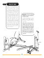
To avoid possible damage to this Leg Press, please follow these assembly steps in the correct order. Before proceeding, find your
new Leg Press’ serial number located on the back of the base tube (1b), and enter here:
Refer to this number when calling for service, and enter this serial number on your Warranty Card and in your own records. Be
sure to read your Owner’s Guide before using your new Leg Press.
If any parts, hardware or tools are missing, please call 1.800.335.4348, Extension 12
NOTE: It is recommended that you apply grease to the threads of each screw as you assemble your Leg Press to
prevent loosening and noise. Also, during each assembly step, ensure that ALL screws are in place and partially threaded in before
completely tightening any ONE screw.
Assembly
Guide
ST250
LEG PRESS

3
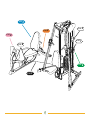
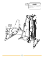
5
STEP
3
STEP
2
STEP
4
STEP
6
STEP
7
STEP
8
STEP
1
STEP

4
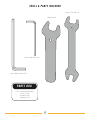
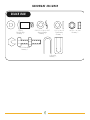
19mm Wrench
6mm L-Shaped Wrench (2)
TOOLS & PARTS INCLUDED
PARTS BOX
Color-coded Hardware Bags
Owner’s Guide
Assembly Guide
Warranty Card
10mm/17mm Wrench
4mm L-Shaped Wrench

5
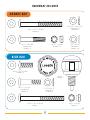
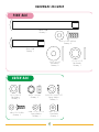
ORANGE BAG
BLUE BAG
HARDWARE INCLUDED
M10 x 1.5P Nut
Quantity: 12
10.5 x 18 x 2T
Flat Washer
Quantity: 16
M10 x 1.5P x 60L
Carriage Bolt
Quantity: 2
SW10.2 x 18.4 x 2.5T
Spring Washer
Quantity: 8
M10 x 1.5P x 100L Bolt
Quantity: 4
M10 x 1.5P Nut
Quantity: 3
M10 x 1.5P x 30L Bolt
Quantity: 8
M10 x 1.5P x 105L Bolt
Quantity: 1
Pull Pin
Quantity: 1
10.5 x 18 x 2T
Flat Washer
Quantity: 4
M10 x 1.5P x 50L
Carriage Bolt
Quantity: 2

6
PINK BAG
GREEN BAG
HARDWARE INCLUDED
10.5 x 18 x 2T
Flat Washer
Quantity: 2
M10 x 1.5P Nut
Quantity: 2
M6 x 1P x 15L Bolt
Quantity: 3
90mm Shaft
Quantity: 1
10.5 x 30 x 2T
Flat Washer
Quantity: 2
165mm Shaft
Quantity: 1
SW6.1 x 12.2 x 1.5T
Spring Washer
Quantity: 3
6.4 x 14 x 1T
Flat Washer
Quantity: 3
SW10.2 x 18.4 x 2.5T
Spring Washer
Quantity: 2
17 x 25 x 1.5T
Flat Washer
Quantity: 1
M10 x 1.5P x 20L Bolt
Quantity: 2

7
BLACK BAG
15x33L
Shoulder Bolt
Quantity: 1
U Bracket
Quantity: 1
M12 Slotted Bolt
Quantity: 1
M10 x 1.5P Nut
Quantity: 1
10.5 x 18 x 2T
Flat Washer
Quantity: 1
SW10.2 x 18.4 x 2.5T
Spring Washer
Quantity: 1
HARDWARE INCLUDED

8
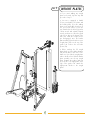
1
STEP
• If you aren’t adding any weight
plates to the stack, skip this step and
proceed to Step 2.
• Your unit is equipped to handle
21-ten pound plates (20 plates and
the header plate). If you are adding
plates to the stack after it has been in
use, proceed as follows: Loosen the
nuts, attached to the bolts (5g) with a
10mm wrench and a 4mm L-shaped
wrench, and remove. Allow the guide
rods (5c) to drop to the bottom of the
tube (1b). With the weight selector
pin disengaged, raise the header
plate assembly (5e) and each successive
weight plate (5d) over the top of the
guide rods. Remove the steel tube
spacer (5a).
• Before stacking the 20 weight
plates back on, place rubber bumpers
(5b) directly above each hole of 1b.
Make sure you slide the weight plates
with no decals on first. Slide the header
plate assembly onto the top weight
plate. Reattach the washers and nuts
to the bolts to the appropriate holes
(5g) of the guide rods. Attach the
appropriate decals to the weight
plates.
WEIGHT PLATES
5c
5e
5d
5b
5a
5g
1b

9
1b
1a
1d
1c
1e
1e
2
STEP
• Attach the connecting brace (1a) to
the empty holes on the left floor
support of the base unit (ST200).
Connect with two carriage bolts
(M10x1.5Px60L), two flat (10.5x18x2T)
& spring (SW10.2x18.4x2.5T) washers,
and two nuts (M10x1.5P). Attach the
opposite end of the connecting brace
to the main floor support (1b) of the
leg press. Attach the two bolts already
in (1b) with two flat (10.5x18x2T)
& spring (SW10.2x18.4x2.5T) washers,
and two nuts (M10x1.5P). Tighten all
four nuts with a 17mm wrench.
• Slide the rear vertical support (1c)
over the top of the protruding bolts on
the rear floor support (1d). Loosely
fasten two flat (10.5x18x2T) & spring
(SW10.2x18.4x2.5T) washers and two
nuts (M10x1.5P) to the bolt ends.
Slide this structure and mate with the
bolts attached to the rear of 1b.
Loosely attach two flat (10.5x18x2T) &
spring (SW10.2x18.4x2.5T) washers
and two nuts (M10x1.5P). Attach the
side supports (1e) to the sides of 1b & 1c.
Fasten with four bolts (M10x1.5Px100L),
eight flat (10.5x18x2T) washers,and
four nuts (M10x1.5P) using a 6mm L-
shaped wrench and a 17mm wrench.
Securely tighten all fasteners.
ORANGE BAG

10
3
STEP
• Lay the seatback (2a) face down.
Mate the seatback support (2b) to 2a.
Make sure the holes of 2b are pointing
up towards the top of the seatback.
Securely fasten four bolts
(M10x1.5Px30L) into the seatback
using a 6mm L-shaped wrench.
Thread the pull pin partially into the
opening of 1b. Guide the seatback
into the oval opening at the rear of the
main support tube (1b). Pull up and
hold the pull pin, while you guide the
seatback in the rest of the way.
Release the pull pin and allow to
engage in one of the holes.
• Bring the handle bars (2c) up to the
bottom of the rectangular seat
support plate of 1b. Place a bolt
(M10x1.5Px105L) and a flat
(10.5x18x2T) washer horizontally
through the seat support tube of 1b.
Attach a flat (10.5x18x2T) washer
and a nut (M6x1P). Leave loose.
• Drop 2 bolts (M10x1.5Px50L)
vertically through the seat support tube
of 1b. Attach two flat (10.5x18x2T)
washers and two nuts (M10x1.5P).
Tighten using a 6mm L-shaped wrench
and a 17mm wrench. Tight the
horizontal hardware with a 10mm
wrench and a 4mm L-shaped wrench.
• Lay the seat (2d) on top of the flat
steel support of 1a. Make sure the
rounded part of the seat is pointed
towards the front. Securely fasten four
bolts (M10x1.5Px30L) up into the
seat using a 6mm L-shaped wrench.
BLUE BAG
1b
2c
2d
2a
2b

11
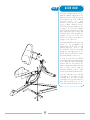
4
STEP
• Insert the lever arm (3a) into the
triangular structure at the front of 1b.
When the holes are lined up, insert the
90mm shaft along with a flat
(17x25x1.5T) washer through the lower
end of 3a and fasten with a flat
(10.5x30x2T) washer and a bolt
(M10x1.5Px20L). Tighten firmly using
two 6mm L-shaped wrenches.
• Insert the foot plate (3b) over the top
opening of the lever arm. When the
holes are lined up, slide the 165mm
shaft through the opening and fasten
a flat (10.5x30x2T) washer and a
bolt (M10x1.5Px20L). Tighten firmly
using a 6mm L-shaped wrench.
PINK BAG
1b
3b
3a

12
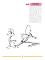
5
STEP
• If you already have the base unit
assembled with cable #2 and are
adding the leg press to it, follow this
instruction, otherwise proceed to Step 6:
Unscrew the nuts and bolt that attaches
cable #2 to the rear termination tube
(6b of base unit), using a 19mm wrench.
Unscrew the nuts from the slotted bolt. Pull
the cable out through the front at
pulley F of the base unit.
CABLE #2
F
Cable #2
6b

13
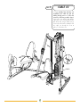
6
STEP
• Attach the pulley structure (U) to the
bottom rear floor support of the base
unit with three bolts (M6x1Px15L), three
flat (6.4x14x1T), and three spring
(SW6.1x12.2x1.5T) washers. Tighten
with a 4mm L-shaped wrench.
• Slide pulley structure (Q) through the
back side of the rear vertical support
(base unit) and fasten securely with
two spring (SW10.2x18.4x2.5T)
& flat (10.5x18x2T) washers and two
nuts (M10x1.5P). Use a 17mm wrench.
• Feed the small steel end of cable
#5 through pulleys (in the following
order) F, G, Q, V. Place the slotted
bolt (5a of base unit) around cable
#5. Thread the nuts back on the slotted
bolt. With the threads pointing up,
thread the bolt into the rear termination
tube (6b of base unit) far enough that
the cable is taught. Tighten the locking
nut against the bottom of 6b using a
19mm wrench.
GREEN BAG
F
U
Q
V
6
b
F
G
V
Q
Cable #5

14
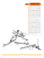
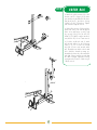
7
STEP
• Begin routing cable #6 with the end
opposite the steel ball end. Feed the
cable over pulley R, under S, around
T, and under U. Unscrew the nut from
the slotted bolt (M12). With the
threads of the bolt facing up, slide
cable #6 through it and reattach the
nut. Thread the bolt into the post of
pulley V, just enough so the cable
won’t fall out. Slip the opposite end of
the cable (ball end fitting) through the
wide opening, on the side of the U
bracket. Place the U bracket over the
cable receptor attachment point on
the main floor support (1b). Line up
the holes and slide the shoulder bolt
(15x33L) through the 3 holes. Attach
a spring (SW10.2x18.4x2.5T) and
flat (10.5x18x2T) washer and nut
(M10x1.5P) using a 6mm L-shaped
wrench and a 17mm wrench. Tighten
until the end of the bolt protrudes
beyond the end of the nut. Do not
crush the U bracket.
BLACK BAG
U
T
S
R
V
Cable #6
Ball End
Fitting
WARNING:
FAILURE TO PROPERLY
COMPLETE THIS STEP COULD RESULT
IN SERIOUS INJURY!
• Go back up and tighten the slotted
bolt (M12), until the cable is taught (a
minimum of 0.5”). Tighten both the
bolt and the locking nut using a
19mm wrench.
NOTE: With the weight selector pin
engaged in the 10 pound hole, pull
on all three cable ends. There should
be no more than 0.5” of play in the
cable. This means that the 10 pound
weight should begin to move vertically,
within 0.5” of cable pull. If there is
more distance than this, tighten the
appropriate bolts until you achieve
0.5” or less. If you over tighten, the
weight selector pin won’t fit easily in
the rod that accommodates the
weight stack.

15
8
STEP
• Attach the decals according to the
diagram below.
DECALS
PINCH POINT
SAFETY DECAL
PLACEMENT

500 South CP Avenue • P.O. Box 280 • Lake Mills. WI 53551
toll free 800.335.4348 • phone 920.648.4090 • fax 920.648.3373
www.visionfitness.com
©2005 Vision Fitness. All Rights Reserved. 10.05
AG18.38PRD
REV2
starts
vision
with a
it all
-
 1
1
-
 2
2
-
 3
3
-
 4
4
-
 5
5
-
 6
6
-
 7
7
-
 8
8
-
 9
9
-
 10
10
-
 11
11
-
 12
12
-
 13
13
-
 14
14
-
 15
15
-
 16
16


Ask a question and I''ll find the answer in the document
Finding information in a document is now easier with AI
Related papers
Other documents
-
Unbranded 0144300830 Operating instructions
-
Liberty Garden SC-K-632SF-4R Installation guide
-
 Consilium Salwico ST200 Calibration Instruction
-
Horizon Fitness X8 Elliptical Owner's manual
-
Powermatic 201HH Planer, 7.5HP 1PH 230V User manual
-
-
-
Wilton 15HH User manual
-
JET JWS-35X5-1 Owner's manual
-
