
Shenzhen JFY Tech Co.,Ltd
XPC series 6-20KVA online UPS


Thank you for using JFY product!
Please observe the warnings on the machine and manual strictly
and properly keep the manual. Do not operate the UPS
before reading through all safety notes and operating instructions.

Safety notes
Operating safety
1. Read safety notes carefully and thoroughly before operation, ensure the
proper usage and save this manual properly.
2. Pay attention to alarm table on the UPS and operate following it.
3. Avoid installing the UPS near water or in excessive humidity.
4. Avoid installing the UPS where it would be exposed to direct sunlight or
nearby heater.
5. The UPS must be stored in a location with good ventilation and ensure
enough space on each side for ventilation.
6. No liquid or spray detergent to clean the UPS.
7. Use powder fire extinguisher in the event of fire occurring in the vicinity.
Liquid fire extinguishing agents may causes electric shock.
Electric safety
1. UPS has provided earthed terminal, in the final installed system
configuration, equipotential earth bonding to the external UPS battery
cabinets, connect the earth before connecting to the building wiring terminal.
2. Before moving or re-wiring the UPS, please disconnect the mains source and
make sure the UPS is completely shut down. If not, the output terminal may
be electrically live that may causes electric shock.
3. Please use fitting and accessories appointed by JFY.
4. To meet the requirement of EMC, the length of output line should be less
than 40m distance.
Battery safety
1. Battery should be replaced periodically to ensure normal UPS operation and
adequate autonomy time because of high ambient temperature shortening the
battery lifetimes.
2. Battery should be managed by professional personnel.
3. Do use the same type and same number of batteries in replacement.
4. In case of electrical shock and high short circuit current, please observe the
precaution as follows:
A. Remove watches, rings, or other metal object from the hands;
B. Use tools with insulated handles;
C. Wear rubber gloves and boots;
D. Do not lay tools or metal parts on top of batteries;
E. Disconnect the load before operate the terminal of battery.
5. Do not attempt to dispose of batteries by burning them. This could cause
battery explosion. The batteries must be rightly deposed according to local

regulation.
6. Do not open or destroy batteries. Escaping electrolyte can cause injury to the
skin and eyes. It may be toxic. If electrolyte comes into contacting with the
skin, wash the affected area with plenty of clean water immediately and go
to the hospital for a check.
7. Do not make the positive and negative terminals of the battery short circuit;
otherwise it may cause electric shock or fire.
Maintenance
The operating environment and storage method are two key factors affecting
the lifetime and reliability of the UPS. Hence, it is advisable not using the
device in the following environments:
1 Where the temperature and relative humidity are outside the
specifications (temperature: 0-40℃, relative humidity: 20-90%).
2 Where vibrations or shocks are existing.
3 Dust, corrosive agents or salts or inflammable gas are present.
If the UPS will remain idle for a long period, it must be stored in a dry
environment. The storage temperature should range from -25-55 (without ℃
battery). Before power on the UPS, set the ambient temperature over 0 and ℃
keep more than 2 hours.

- 5 -
Safety notes
1 Introduction…………………………………………………………………………… 1
1.1 Sign explain ………………………………………………………………… 1
1.2
Front view……………………………………………………………………… 2
1.3
Back view…………………………………………………………………… 2
1.4
Technical data ………………………………………… ……… …………… 4
2 Installation …………………………………………………………………………… 5
2.1
Unpacking and check ……………………………………………………… 5
2.2
Cable list ……………………………………………………………… 6
2.3
UPS Connecting …………………………………………………………… 6
2.4 Installation for long backup model ………………………………… 8
2.5 Connect to the RS232 communication port ……………………… 9
2.6
Parallel card (Optional)……………………………………………… 9
2.7
Installation of the intelligent card …………………………………… 13
2.8
EPO ……………………………………………………………………………… 14
2.9 Maintenance switch ……………………………………………………… 15
2.10
Dust-proof net (Optional) ……………………………………………… 16
2.11
Isolation transformation box (Optional) ………………………… 16
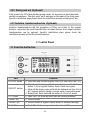
3 Control Panel ……………………………………………………………………… 16
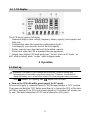
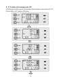
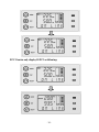
4 Operation ………………………………………………………………………… 17
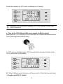
4.1 Start up ……………………………………………………………………… 17
4.2
Shut down …………………………………………………………………… 21
5 Battery Maintenance. …………………………………………………………… 23
6 Trouble Shooting………………………………………………………………… 24
7 Signification of Fault code ……………………………………… 26
8 JFY-tech Contact Information ……………………………………………… 27

- 1 -
1 Introduction
This series UPS is a advanced on-line sine wave uninterruptible power system
with parallel redundancy function and the maintenance switch is optional. Provide
a high quality AC power for your precision equipment with a wide range of
application. It’s ideally suited for computer equipment, communication system,
industry automatic control equipment. Because of the on-line design, the input
voltage always would be adjusted and filtered differing from backup UPS. When
power outage, battery will supply the load without transfer time. When over load or
fault of inverter,UPS will turn to bypass mode and supplied by the utility power.
At the time of eliminating over load,UPS will automatically turn to supplied by
the inverter.
This manual is suitable for XPC series produces as follows:
1106:inner battery normal model
1106L:external battery long backup model
1110:inner battery normal model
1110L:external battery long backup model
3110L:3 phase in, 1phase out, external battery long backup model
3115L:3 phase in, 1phase out, external battery long backup model
3120L:3 phase in, 1phase out, external battery long backup model。
Meanwhile each model can be divided into normal and professional version for
user choice. Professional version is added with EPO switch and manual
maintenance switch, please check 2.8, 2.9 section。
1.1 Sign explain
Sign Meaning
Attention
Danger
AC
DC
Equipment grounding conductor
Grounding (Earth)
Recycling
Do not dispose of unsorted waste
Over load
Battery
ON/OFF button

- 2 -
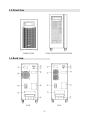
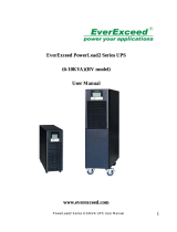
1.2 Front view
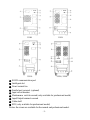
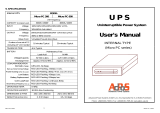
1.3 Back view
1106L/ 1110L
1106/ 1110/ 3110L/ 3115L/ 3120L
1106
1110

- 3 -
①
RS232 communication port
② Intelligent slot
③ Direct current fan
④ Parallel port covered (optional)
⑤ Input circuit breaker
⑥ Maintenance switch covered (only available for professional model)
⑦ Input/Output terminal covered
⑧ Cable shelf
⑨ EPO (only available for professional model)
Notice: the views are available for the normal and professional model.
1106L
1110L
3310L
3315L/ 3320L

- 4 -
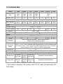
1.4 Technical data
Model 1106 1106L 1110 1110L 3110L 3115L 3120L
Size(W×L×H)
mm
248×
500×
616
240×
500×
460
248×
500×
616
240×
500×
460
248×
500×
616
Weight(Kg)
57 20 59 21 27 35 35
Power
Rated capacity
6KVA
4.8KW
6KVA
4.8KW
10KVA
8KW
10KVA
8KW
10KVA
8KW
15KVA
12KW
20KVA
16KW
Input
Voltage Range
120VAC~275VAC
*Max Current
33A 37A 55A 59A 86A 112A
Frequency 46Hz~54Hz
Power factor 0.99 0.95
Output
Rated voltage
220VAC×(1±1%)
Current 27A 45A 68A 91A
Frequency
46Hz~54Hz(On line mode,follow utility power )
50Hz×(1±0.1%)(Battery mode)
Power factor 0.8
Over load
ability
105%~125%, After 1 minutes turn to bypass mode, After 30 minutes turn
off output; 125%~135%, After 30s turn to bypass mode. After 1 minutes
turn off output; >135%, After 0.1s turn to bypass mode
Peak Factor 3:1
THD THD<2% (linear load)
Battery(High ambient temperature and deep discharge will shorten the battery life)
Backup time
4 minutes
(full load)
Depend on
external
battery
4 minutes
(full load)
Depend on external battery
Charge time
7 hours
charge to
90%
Depend on
external
battery
7 hours
charge to
90%
Depend on external battery
* Max current is when the UPS working with 187V DC input, full load output, full
load charge.

- 5 -
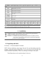
Model
1106 1110 1110L 3110L 3115L 3120L
EMC
ESD IEC61000-4-2 Level 4
RS IEC61000-4-3 Level 3
EFT IEC61000-4-4 Level 4
Surge IEC61000-4-5 Level 4
Operation
temperature
0℃-40℃
Storage
temperature
-25℃-55℃
Humidity 20%-90% (non condensation)
Altitude <1000m
Height (m) 1000 1500 2000 2500 3000 3500 4000 4500 5000
Capacity rate 100% 95%
91% 86% 82% 78% 74% 70% 67%
Attention: when UPS worked in the height over 1000m, the output rated power
must be decrease progressively referring to the above table.
2.Installation
Danger: Be careful when installation before cutting off AC power switch or
cutting of the battery input for long backup model.
Attention: >> Installation and wiring must be performed in accordance with the
local electric laws/regulations and execute by professional personnel.
>> Advise to be used on ground
2.1 Unpacking and check
Accessory:a. One user manual b. Terminal
NOTE: Before installation, please inspect the unit. Be sure that nothing inside the
package is damaged during transportation. Do not turn on the unit and notify the
carrier and dealer immediately if there is any damage or lacking of some parts.
Recycling: please save the original package for future use.

- 6 -
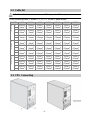
2.2 Cable list
Attention: Cable’s diameter and wire’s CSA depend on UPS rated power.
In the following chart, L means L1, L2, L3 for the 3 phase model.
MODEL
1106 1106L 1110 1110L 3110L 3115L 3120L
IN PUT
G
10AWG
(6mm
2
)
10AWG
(6mm
2
)
8AWG
(10mm
2
)
8AWG
(10mm
2
)
8AWG
(10mm
2
)
6AWG
(25mm
2
)
6AWG
(25mm
2
)
N
10AWG
(6mm
2
)
10AWG
(6mm
2
)
8AWG
(10mm
2
)
8AWG
(10mm
2
)
8AWG
(10mm
2
)
6AWG
(25mm
2
)
6AWG
(25mm
2
)
L
10AWG
(6mm
2
)
10AWG
(6mm
2
)
8AWG
(10mm
2
)
8AWG
(10mm
2
)
8AWG
(10mm
2
)
6AWG
(25mm
2
)
6AWG
(25mm
2
)
BATTERY
+
10AWG
(6mm
2
)
10AWG
(6mm
2
)
8AWG
(10mm
2
)
8AWG
(10mm
2
)
8AWG
(10mm
2
)
6AWG
(25mm
2
)
6AWG
(25mm
2
)
-
10AWG
(6mm
2
)
10AWG
(6mm
2
)
8AWG
(10mm
2
)
8AWG
(10mm
2
)
8AWG
(10mm
2
)
6AWG
(25mm
2
)
6AWG
(25mm
2
)
G
10AWG
(6mm
2
)
10AWG
(6mm
2
)
8AWG
(10mm
2
)
8AWG
(10mm
2
)
8AWG
(10mm
2
)
6AWG
(25mm
2
)
6AWG
(25mm
2
)
OUT PUT
L
10AWG
(6mm
2
)
10AWG
(6mm
2
)
8AWG
(10mm
2
)
8AWG
(10mm
2
)
8AWG
(10mm
2
)
6AWG
(25mm
2
)
6AWG
(25mm
2
)
N
10AWG
(6mm
2
)
10AWG
(6mm
2
)
8AWG
(10mm
2
)
8AWG
(10mm
2
)
8AWG
(10mm
2
)
6AWG
(25mm
2
)
6AWG
(25mm
2
)
G
10AWG
(6mm
2
)
10AWG
(6mm
2
)
8AWG
(10mm
2
)
8AWG
(10mm
2
)
8AWG
(10mm
2
)
6AWG
(25mm
2
)
6AWG
(25mm
2
)
2.3 UPS Connecting

- 7 -
Danger: Ensure the power cable with circuit breaker protection, and pay attention to
the capacity, if not, may destroy AC switch. (MAX input current refer to 1.4
technical data)
Please refer to 2.2 cable list to choose the fit input & output cable
Remove the cover plate of terminal tier①
Connect output cable to the output terminal
Connect input cable to the input terminal
Connect battery to the battery terminal (only for long-backup model)
Use tie across truss rope shelf②
Use tie truss input, output, battery input cable
Put back the cover plate①
Make sure connection be correct,then switch on AC power,Put UPS input
switch “ON”,then UPS work normally
Danger:Please ensure the fastness of connection.
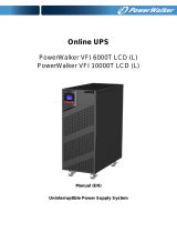
Input & Output terminal for single phase model:
Input & Output terminal for three phase model:
1106/1110 1106L/ 1110L
3110L/ 3115L/ 3120L

- 8 -
2.4 Installation for long backup model
The long backup model (except for special model with 20pcs battery) with battery
voltage 192VDC can be connected with 16sets battery, battery can be paralleled
with many groups; Special model with battery voltage 240VDC can be connected
with 20sets battery, battery can be paralleled with many groups. In case of electric
shock, please observe strictly the following procedure:
1) Turn off battery switch “OFF”, with suitable series battery.
2) Choose the fit battery cable to connect battery and UPS (refer to 2.2 Cable list).
Between UPS and battery must have a DC breaker, whose voltage and current
must be in the range of UPS as follows:
16 pcs battery 192VDC
MODEL
1106(L)
1110(L) 3110L 3115L
3120L
Bat volta
g
e
192VDC
192VDC 192VDC
192VDC
192VDC
Bat current
34A. max
56A. max 56A. max 83A.max 112A. max
20 pcs battery 240VDC
MODEL
1106(L)
1110(L) 3110L 3115L
3120L
Bat volta
g
e
240VDC 240VDC 240VDC
240VDC
240VDC
Bat current
27A. max 45A. max 45A. max 68A. max 91A. max
3) Before connecting to the UPS, Ensure no load connected. After connection turn
on battery switch “ON”, switch on AC, the UPS begin to charge for battery.
Danger:Do not connect the cable to the UPS first. Otherwise, it maybe causes the
hazard of electric shock.
Attention: the battery ground with logo is on the right side of main case terminal
tier
.

- 9 -
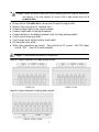
2.5 Connect to the RS232 communication port
RS232 communication port: connect the UPS and the monitor
The RS232 communication cable conncet to the serial port of the computer
The RS232 communication cable conncet to the RS232 communication port of
UPS.
The DIN configuration of the RS232 interface port on UPS is as following:
2.6 Parallel card(Optional)
Redundancy ntroduce
N+X is the now dependable power supply structure. N is indicate the least number
of UPS all the load need; X is indicate the redundancy number of UPS that can be
suppoted by the system. More bigger of X, more dependable of the system. N+X is
the best solution for the high dependable situation. Just with parallel card and data
line, it can be paralleled with maximum 3 UPS.
Parallel installation
Parallel function is optional. You can buy parallel fittings by yourself (including
parallel card and data line) . customer service staff will install to ups, The max
number of parallel is 3, Parallel UPS must have independent battery.

- 10 -
Remove the cover plate of parallel , install data line
1) Parallel card is between of ups`s communication port,with parallel card,use
the data Line successively connection
2) All of UPS output cable connect to a connection tray, Then use the connection
tray to load
Attention: Output cable require:
If the distance between ups to load less then 20m, require every UPS output cable
length disparity under 20%; If the distance between ups to load over then 20m, require
every UPS output cable length disparity under 10%.
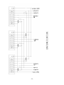
3) Parallel UPS terminal tier input, output connection, as under picture, input,
output cable follow single UPS match cable require.

- 11 -

- 12 -
Out
p
ut
Ground
Battery3#
In
p
ut L1
p
hase
In
p
ut L2
p
hase
In
p
ut L3
p
haseIn
p
ut L3
p
hase
In
p
ut N
In
p
ut GND
Battery 1#
Battery 2#

- 13 -
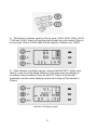
4) operation explain
General operation must follow the one of single ups
Parallel UPS with AC turn on: switch on AC, only press anyone of ups, the
other UPS will turn on at the same time, Then UPS turn to bypass model;
Battery mode turn on: Firstly short press every ups on/off button, UPS start
building assist power supply, Then long press anyone of ups, The other UPS
will turn on at the same time, all ups will work on battery mode.
Parallel ups turn off: press and hold on/off button of anyone ups more than 4S
(the buzzer will beep twice), then parallel ups shut down; press and hold on/off
button of anyone ups button more than 1S, less than 4S (the buzzer will beep
twice), then single ups shut down.
Attention: long press is more than 1s, short press is less than 0.5S.
2.7 Installation of the intelligent card
You don’t need to stop the UPS during the installation of communication card.
1) Remove the cover plate of slot
2) Insert the intelligent card into the slot
3) Secure the intelligent card with two screws.
SNMP card (Optional)
Be located of back panel intelligent card slot, Supply the SNMP allow data

- 14 -
AS400 card (Optional)
Only need Insert AS400 (Optional) card into the intelligent card slot, Immediately
realize use AS400 system monitoring UPS, manage the power supply. PIN explain:
PIN Meaning
PIN1
Conduction: UPS breakdown
PIN2
Conduction: warning
PIN3
Ground connection (Ground)
PIN4
Remote shut down
PIN5
Public point none conduction: UPS work
PIN6
Conduction: bypass action
PIN7
Conduction: battery low voltage
PIN8
Conduction: UPS Work
none conduction: bypass work
PIN9
Conduction: AC cut off
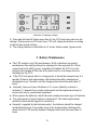
2.8 EPO
EPO (Emergent Power Off) is located of UPS back panel, green terminal, Use
EPO function shut down ups with Emergent circumstance, Two ways connection:
Connect 1
1-2 conduction, UPS execute shut down
3-4 free
Emer
g
ent Power Off
Page is loading ...
Page is loading ...
Page is loading ...
Page is loading ...
Page is loading ...
Page is loading ...
Page is loading ...
Page is loading ...
Page is loading ...
Page is loading ...
Page is loading ...
Page is loading ...
Page is loading ...
-
 1
1
-
 2
2
-
 3
3
-
 4
4
-
 5
5
-
 6
6
-
 7
7
-
 8
8
-
 9
9
-
 10
10
-
 11
11
-
 12
12
-
 13
13
-
 14
14
-
 15
15
-
 16
16
-
 17
17
-
 18
18
-
 19
19
-
 20
20
-
 21
21
-
 22
22
-
 23
23
-
 24
24
-
 25
25
-
 26
26
-
 27
27
-
 28
28
-
 29
29
-
 30
30
-
 31
31
-
 32
32
-
 33
33


Shenzhen 1106L User manual
- Type
- User manual
Ask a question and I''ll find the answer in the document
Finding information in a document is now easier with AI
Other documents
-
EMC UPS 10000VA User manual
-
 PowerWalker PowerWalker VFI 40000TP 3/3 BX Owner's manual
-
 EverExceed 6K User manual
-
 adpos micro PC Series User manual
-
EAST EA2150-LCD User manual
-
 PowerWalker VFI 10000 T Owner's manual
-
Epever TP20KB Pure Sine Wave Inverter User manual
-
OutBack Power Alino User manual
-
PowerWalker VFI 10000 TP 3/1 BI Owner's manual
-
 BlueWalker PowerWalker VFI 10000TP 3/1 User manual


