Century HRC12A8RAMSCFL Installation, Operation & Maintenance Manual
- Category
- Heat pumps
- Type
- Installation, Operation & Maintenance Manual
This manual is also suitable for

Heat Controller • 1900 Wellworth Ave. • Jackson, MI 49203 • (517)787-2100 • www.heatcontroller.com
INSTALLATION, OPERATION
MAINTENANCE
HRC Series
Commercial Console
Water-Source Heat Pumps
60Hz

Installation, Operation, Maintenance HRC SERIES Heat Controller
2
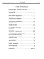
Table of Contents
Model Nomenclature: Console (HRC) Series (60Hz) ...................................3
General Information ................................................................................... 4-5
Unit Physical Data .........................................................................................6
Installation ................................................................................................. 7-8
Piping Connections - HRC Size 06-15 ..........................................................9
Piping Connections - HRC Size 18.........................................................10-11
Water-Loop Heat Pump Applications ...........................................................12
Ground-Loop Heat Pump Applications ........................................................13
Ground-Water Heat Pump Applications ................................................. 14-15
Water Quality Standards .............................................................................16
Electrical - Line Voltage ......................................................................... 17-18
Electrical - Low Voltage ......................................................................... 19-20
HRC Series Wiring Diagram Matrix .............................................................21
CXM Controls ..............................................................................................22
DXM Controls ........................................................................................ 23-24
Safety Features - CXM/DXM Controls................................................... 25-26
Unit Commissioning and Operating Conditions ...........................................27
Piping System Cleaning and Flushing .........................................................28
Unit and System Checkout Procedure ........................................................29
Unit Start-Up Procedure ..............................................................................30
Unit Operating Conditions ..................................................................... 31-32
Start-Up Log Sheet ......................................................................................33
Preventive Maintenance ..............................................................................34
Functional Troubleshooting .........................................................................35
Preventive Maintenance ..............................................................................36
Performance Troubleshooting .....................................................................37
Revision History............................................................................Back Cover

Heat Controller HRC SERIES Installation, Operation, Maintenance
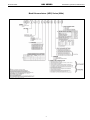
Model Nomenclature: (HRC) Series (60Hz)
3

Installation, Operation, Maintenance HRC SERIES Heat Controller
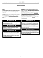
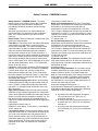
General Information
WARNING! To avoid the release of refrigerant into the
atmosphere, the refrigerant circuit of this unit must be
serviced only by technicians who meet local, state, and
federal prociency requirements.
WARNING! All refrigerant discharged from this unit must
be recovered WITHOUT EXCEPTION. Technicians must
follow industry accepted guidelines and all local, state, and
federal statutes for the recovery and disposal of refrigerants.
If a compressor is removed from this unit, refrigerant circuit
oil will remain in the compressor. To avoid leakage of
compressor oil, refrigerant lines of the compressor must be
sealed after it is removed.
CAUTION! To avoid equipment damage, DO NOT use
these units as a source of heating or cooling during the
construction process. The mechanical components and lters
will quickly become clogged with construction dirt and debris,
which may cause system damage.
WARNING!
WARNING!
WARNING!
CAUTION!
Safety
Warnings, cautions, and notices appear throughout this
manual. Read these items carefully before attempting
any installation, service, or troubleshooting of the
equipment.
DANGER: Indicates an immediate hazardous situation,
which if not avoided will result in death or serious
injury. DANGER labels on unit access panels must be
observed.
WARNING: Indicates a potentially hazardous situation,
which if not avoided could result in death or serious injury.
CAUTION: Indicates a potentially hazardous situation or
an unsafe practice, which if not avoided could result in
minor or moderate injury or product or property damage.
NOTICE: Notication of installation, operation, or
maintenance information, which is important, but which is
not hazard-related.
WARNING! The EarthPure
®
Application and Service Manual
should be read and understood before attempting to service
refrigerant circuits with HFC-410A.
WARNING!
WARNING! The installation of water-source heat pumps and
all associated components, parts, and accessories which
make up the installation shall be in accordance with the
regulations of ALL authorities having jurisdiction and MUST
conform to all applicable codes. It is the responsibility of
the installing contractor to determine and comply with ALL
applicable codes and regulations.
4

Heat Controller HRC SERIES Installation, Operation, Maintenance
5
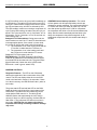
Inspection -
Upon receipt of the equipment, carefully
check the shipment against the bill of lading. Make sure all
units have been received. Inspect the packaging of each
unit, and inspect each unit for damage. Insure that the
carrier makes proper notation of any shortages or damage
on all copies of the freight bill and completes a common
carrier inspection report.
Storage - Equipment should be stored in its original
packaging in a clean, dry area. Store units in an upright
position at all times. Stack units a maximum of 3 units
high.
Unit Protection -
Cover units on the job site with either the
original packaging or an equivalent protective covering. Cap
the open ends of pipes stored on the job site. In areas where
painting, plastering, and/or spraying has not been completed,
all due precautions must be taken to avoid physical damage
to the units and contamination by foreign material. Physical
damage and contamination may prevent proper start-up and
may result in costly equipment clean-up.
Examine all pipes, ttings, and valves before installing
any of the system components. Remove any dirt or
debris found in or on these components.
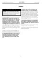
Pre-Installation - Installation, Operation, and
Maintenance instructions are provided with each
unit. Horizontal equipment is designed for installation
above false ceiling or in a ceiling plenum. Other unit
congurations are typically installed in a mechanical
room. The installation site chosen should include
adequate service clearance around the unit. Before unit
start-up, read all manuals and become familiar with the
unit and its operation. Thoroughly check the system
before operation. Make sure wall behind the unit is at
and smooth.
Prepare units for installation as follows:
1. Compare the electrical data on the unit nameplate
with ordering and shipping information to verify that
the correct unit has been shipped.
2. Keep the cabinet covered with the original packaging
until installation is complete and all plastering,
painting, etc. is nished.
3. Verify refrigerant tubing is free of kinks or dents and
that it does not touch other unit components.
4. Inspect all electrical connections. Connections must
be clean and tight at the terminals.
CAUTION! DO NOT store or install units in corrosive
environments or in locations subject to temperature or
humidity extremes (e.g., attics, garages, rooftops, etc.).
Corrosive conditions and high temperature or humidity can
signicantly reduce performance, reliability, and service life.
Always move and store units in an upright position. Tilting
units on their sides may cause equipment damage.
CAUTION!
CAUTION!
CAUTION! CUT HAZARD - Failure to follow this caution may
result in personal injury. Sheet metal parts may have sharp
edges or burrs. Use care and wear appropriate protective
clothing, safety glasses and gloves when handling parts and
servicing heat pumps.
General Information

Installation, Operation, Maintenance HRC SERIES Heat Controller
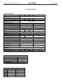
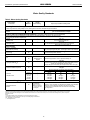
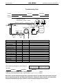
Unit Physical Data
Model 09 12 15 18
Compressor (1 Each)
Factory Charge HFC-410A (oz) [kg] 28 [0.794] 29 [0.822] 33 [0.907] 39 [1.105]
Blower Wheel
Blower Wheel Size (dia x w) -
(in) [mm] - Qty 2
5.25 x 6.25 [133 x 159]
Water Connection Size
O.D. Sweat (in) [mm] 1/2 [12.7] 3/4 [19.1]
Optional FPT Fittings (in) 1/2 3/4
Optional MPT Fittings (in) 1/2 3/4
Coax Volume
Volume US Gal
[Liters]
.09
[.34]
.09
[.34]
.23
[.87]
.26
[.98]
Condensate Connection Size
I.D. Vinyl Hose (In) [mm] 5/8 [15.9]
Air Coil Size
Dimensions (h x w) - (in) [mm]
8 x 26
[203 x 660]
10 x 26
[254 x 660]
10 x 32
[254 x 812]
Filter Size
Bottom Return (in) [mm] 1 - 10 x 30 x 1 [254 x 762 x 25] 1 - 10 x 36 x 1 [254 x 914 x 25]
Front Return (In) [mm] 1 - 7 x 29.5 x 1/8 [178 x 749 x 3.2] 1 - 7 x 35.5 x 1/8 [178 x 902 x 3.2]
Cabinet Size
Bottom Return (Std. 5” Base)
(W x H x D) - (In) [mm]
48 x 26 x 12 [1219 x 660 x 305] 54 x 26 x 12 [1372 x 660 x 305]
Front Return (No Subbase)
(W x H x D) - (In) [mm]
48 x 21 x 12 [1219 x 533 x 305] 54 x 21 x 12 [1372 x 533 x 305]
Cabinet Size
Weight - Operating, (lbs) [kg] 175 [79] 180 [82] 190 [86.2] 220 [99.8]
Weight - Packaged, (lbs) [kg] 185 [83.9] 190 [86] 200 [90.8] 232 [105.2]
* Data not available at time of publication.
All units have rubber grommet compressor mountings and TXV expansion devices.
Unit Maximum Water Working Pressure
Options
Max Pressure PSIG [kPa]
Base Unit
500 [3,445]
Internal Secondary Pump (ISP)
145 [999]
Internal Motorized Water Valve (MWV)
300 [2,068]
Internal Auto Flow Valve
500 [3,445]
Use the lowest maximum pressure rating when multiple options are combined.
(HRC) Series (60Hz)
Optional Factory Installed Auto Flow Regulator GPM [LPS]
Model 2.25 GPM/Ton 3 GPM/Ton
9
2.0 [.126] 2.5 [.158]
12
2.5
[.158] 3.0 [.189]
15
3.0
[.189] 3.5 [.221]
18
3.5
[.221] 4.0 [.252]
Use the lowest maximum pressure rating when multiple options are combined.
6

Heat Controller HRC SERIES Installation, Operation, Maintenance
Installation
1. Console units are typically installed along an outside
wall of the room. Provide adequate space in front
of the unit for service and maintenance. Locate
the Console Unit so that it provides adequate air
circulation throughout the room.
2. Unpack the Console Unit from the shipping carton.
Remove the front cabinet by lifting up and away
from the backplate. Protect the cabinet from damage
during installation by returning it to its original
packaging until required.
3. Using a carpenter's square and a level, ensure the
unit is level. Shim the unit if necessary to assure
proper installation.
4. Select the proper fasteners to connect the backplate
securely to the wall.
5. Fasten the backplate onto the wall through the screw
holes located in the back ange. Secure the subbase
in place.
6. Make all necessary electrical connections as
described in the Electrical Wiring section of this
manual. Consult the wiring diagram to ensure proper
hook-up.
7. Connect the nal piping as described in the Supply
and Return Piping and Condensate Piping section
of the manual. Install shut-off valves, piping and/or
hoses and other accessories as specied.
8. Before making the nal water connections, ush the
system as described in the Start Up section of this
manual. After ushing the system, connect piping and
hoses to the proper supply, return and condensate
connections of the unit.
Note: When necessary, use adapters to connect
hoses.
9. Install any other system components as required
following manufacturer's instructions.
10. After Start-up, reinstall the front cabinet by
carefully lowering the front cabinet over the chassis
onto the backplate.
Supply and Return Hoses - Optional pressure-rated
hose assemblies 300 psi [2067 kPa] are available for use
with Heat Controller Console Units. Use the following
guidelines when installing supply and return hose
assemblies.
1. Install supply and return hoses tted with swivel-joint
ttings at one end to prevent the hose from twisting.
2. Use adapters to secure the hose assembly to the unit
and the riser.
3. Do not allow the hose to twist during installation.
Twisting may damage the hose wall or the interior
rubber compound.
4. Use pipe joint compound sparingly on the pipe
threads of the tting adapters.
5. Prevent sealant from reaching the ared surfaces of
the joint.
6. Do not use pipe joint compound when teon thread
tape is pre-applied to hose assemblies or when
ared-end connections are used.
7. Maximum torque which may be applied to brass
ttings is 30 ft-lbs [41 N-m]. When a torque wrench
is not used, tighten brass ttings nger-tight plus one
quarter turn.
8. Tighten steel ttings as necessary.
9. Shut-off/balancing valves, ow indicators, and drain
tees in the supply runout and return at each oor to
aid in loop balancing and servicing.
The installation of Console Water-Source Heat Pumps
and all associated components, parts and accessories
that make up the installation shall be in accordance with
the regulations of ALL Authorities having jurisdiction
and MUST conform to all applicable Codes. It is the
responsibility of the Installing Contractor to determine
and comply with ALL applicable Codes and Regulations.
Note: An Installation Checklist is provided in this
manual. Complete this checklist after all installation
procedures are completed. A periodic maintenance
checklist provided in the Maintenance section
outlines recommended maintenance schedules. A
Start-Up Inspection Log is also included at the end of
this manual to encourage thorough unit checkout at
initial start-up. These checklists are not a substitute
for the detailed information found in the Installation
section of this manual
.
CAUTION! Poor or inadequate installation may result in
noisy unit operation or unattractive installation.
CAUTION!
7

Installation, Operation, Maintenance HRC SERIES Heat Controller
CAUTION!
CAUTION! Loop Fluids should be of good quality with no
more than 0.50 ppm of chlorides w/copper heat exchangers
(125 ppm w/ Cupro-nickel) to prevent corrosion and should
also be ltered to a maximum 800 micron [0.8mm particle
size to prevent erosion of the heat exchangers.
Installation
Condensate Piping - Unit is supplied with condensate
drain hose, 5/8 inch [16mm] I.D. exible plastic
nonpressure-rated, protruding from piping side of unit.
Connect this hose to building drain. Avoid making kinks
in hose to ensure an unobstructed ow of condensate
from the unit to the drain. DO NOT twist, pull hose out,
or push excess hose into unit. If hose will not connect to
your building drain several options include, relocate end
of building drain, add to or cut hose, use hard plastic or
copper elbow ttings for tight radii (put inside hose). Keep
hose positioned within or over subbase area so hose
does not interfere with front cabinet. Cabinet should not
push or reroute hose. Clamp all joints watertight. Check
for leaks.
Internally the drain hose is clamped to drain pan and
pitched correctly. Horizontal runs of condensate hose
should be pitched downward 1/4 inch minimum for every
foot [10mm per 46cm] of hose. Avoid low points because
dirt collects in these areas and may cause blockage. If
blocked the condensate level in drain pan increases.
When the level gets too high, the Console unit has
sensor switch that will shut unit off. Overow may still
occur.
If the building drain connection is parallel with oor,
the height can be up to 1-1/2 inches [38mm] above
the subbase for proper pitch and correct drainage. Up
to 5 inches [127mm] above the subbase is allowable,
but drainage will be slower. When the drain connection
is 2-1/2 to 5 inches [64 to 127mm] above, the hose
inside the unit will act as a trap. Heights of more than 5
inches [127mm] above the subbase are NOT allowable
(condensate overow may occur). If the unit has a
disconnect option, drain locations are limited. See unit
conguration pages for details.
Field installation of a trap or vent is not required unless
specied by local codes. Console units are designed
in a blow-through conguration. The condensate drain
pan is located on the outlet side of the blower so that
the pressure in the drain pan is higher than atmospheric
pressures.
When drain connection is completed check for proper
drainage and leaks. Correct if necessary.
If trap is used, check and clean often. See Preventive
Maintenance Instructions.
8

Heat Controller HRC SERIES Installation, Operation, Maintenance
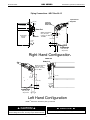
Left Hand Configuration
Water In
Water Out
Notes:
* Dimension reduced by fitting if selected
2.72
(96)
Right Hand Configuration
Water In
Water Out
Blower Deck
Blower Access Panel
Compressor
Access
Panel
Control Box
1.84
(47)
0.75
(19)
20.50
(521)
40.98
(1040)
Condensate
Condensate
5/8" (15.9) ID
Vinyl Hose
Optional
Motorized
W
ater Valve
Optional
Autoflow
V
alve
W
ater Connections
5/8" (15.9)
OD Copper,
1/2" FPT or
1/2" MPT
Optional
Disconnect Box
(mounted to cabinet
not chassis)
Optional
Motorized
Water Valve
Optional
Autoflow
Valve
Water Connections
5/8" (15.9AA)
OD Copper,
1/2" FPT or
1/2" MPT
Optional Fused
Disconnect Box
(mounted to cabinet
not chassis)
Also Available in Non-Fused
Optional Disconnect
Only Box (All Configurations)
Optional Flow
Regulator
Optional
Motorized
Water Valve
1.75 (44)
Out
In
Water Connections
5/8Ó (15.9) OD
Copper, 1/2Ó FPT, or
1/2Ó MPT
2.25
(57)
In
Out
*
11.25 (286)
2.00
(51)
1.50 (38)
8.00 Min
(203)
2.25
(57)
5/8" (15.9) ID
Vinyl Hose
8.00 Min
(203)
Water Connections
5/8Ó (15.9) OD
Copper, 1/2Ó FPT,
or 1/2Ó MPT
*11.25 (286)
1.62 (41)
2.00
(51)
2.25
(57)
CAUTION!ÊÊCorrosiveÊsystemÊwaterÊrequiresÊcorrosionÊ
treatment.
� CAUTION! �
CAUTION!ÊPipingÊmustÊcomplyÊwithÊallÊapplicableÊcodes.
� CAUTION! �
Left Hand Configuration
Water In
Water Out
Notes:
*
Dimension reduced by fitting if selected
2.72
(96)
Right Hand Configuration
Water In
Water Out
Blower Deck
Blower Access Panel
Compressor
Access
Panel
Control Box
1.84
(47)
0.75
(19)
20.50
(521)
40.98
(1040)
Condensate
Condensate
5/8" (15.9) ID
Vinyl Hose
Optional
Motorized
Water Valve
Optional
Autoflow
Valve
Water Connections
5/8" (15.9)
OD Copper,
1/2" FPT or
1/2" MPT
Optional
Disconnect Box
(mounted to cabinet
not chassis)
Optional
Motorized
Water Valve
Optional
Autoflow
Valve
Water Connections
5/8" (15.9AA)
OD Copper,
1/2" FPT or
1/2" MPT
Optional Fused
Disconnect Box
(mounted to cabinet
not chassis)
Also Available in Non-Fused
Optional Disconnect
Only Box (All Configurations)
Optional Flow
Regulator
Optional
Motorized
Water Valve
1.75 (44)
Out
In
Water Connections
5/8Ó (15.9) OD
Copper, 1/2Ó FPT, or
1/2Ó MPT
2.25
(57)
In
Out
*11.25 (286)
2.00
(51)
1.50 (38)
8.00 Min
(203)
2.25
(57)
5/8" (15.9) ID
Vinyl Hose
8.00 Min
(203)
Water Connections
5/8Ó (15.9) OD
Copper, 1/2Ó FPT,
or 1/2Ó MPT
*11.25 (286)
1.62 (41)
2.00
(51)
2.25
(57)
CAUTION!ÊÊCorrosiveÊsystemÊwaterÊrequiresÊcorrosionÊ
treatment.
� CAUTION! �
CAUTION!ÊPipingÊmustÊcomplyÊwithÊallÊapplicableÊcodes.
� CAUTION! �
Piping Connections - HRC Size 06-15
CAUTION! Corrosive system water requires corrosion
resistant ttings and hoses, and may require water treatment.
CAUTION! Piping must comply with all applicable codes.
CAUTION!
CAUTION!
9

Installation, Operation, Maintenance HRC SERIES Heat Controller
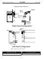
Piping Connections - HRC Size 18
CAUTION! Corrosive system water requires corrosion
resistant ttings and hoses, and may require water treatment.
CAUTION! Piping must comply with all applicable codes.
Left Hand Configuration
Water In
Water Out
Notes:
* Dimension reduced by fitting if selected
2.72
(96)
Right Hand Configuration
Water In
Water Out
Blower Deck
Blower Access Panel
Compressor
Access
Panel
Control Box
1.84
(47)
0.75
(19)
20.50
(521)
40.98
(1040)
Condensate
Condensate
5/8" (15.9) ID
Vinyl Hose
Optional
Motorized
Water Valve
Optional
Autoflow
Valve
Water Connections
5/8" (15.9)
OD Copper,
1/2" FPT or
1/2" MPT
Optional
Disconnect Box
(mounted to cabinet
not chassis)
Optional
Motorized
Water Valve
Optional
Autoflow
Valve
Water Connections
5/8" (15.9AA)
OD Copper,
1/2" FPT or
1/2" MPT
Optional Fused
Disconnect Box
(mounted to cabinet
not chassis)
Also Available in Non-Fused
Optional Disconnect
Only Box (All Configurations)
Optional Flow
Regulator
Optional
Motorized
Water Valve
1.75 (44)
Out
In
Water Connections
5/8Ó (15.9) OD
Copper, 1/2Ó FPT, or
1/2Ó MPT
2.25
(57)
In
Out
*11.25 (286)
2.00
(51)
1.50 (38)
8.00 Min
(203)
2.25
(57)
5/8" (15.9) ID
Vinyl Hose
8.00 Min
(203)
Water Connections
5/8Ó (15.9) OD
Copper, 1/2Ó FPT,
or 1/2Ó MPT
*11.25 (286)
1.62 (41)
2.00
(51)
2.25
(57)
CAUTION!ÊÊCorrosiveÊsystemÊwaterÊrequiresÊcorrosionÊ
treatment.
� CAUTION! �
CAUTION!ÊPipingÊmustÊcomplyÊwithÊallÊapplicableÊcodes.
� CAUTION! �
CAUTION!
CAUTION!
10

Heat Controller HRC SERIES Installation, Operation, Maintenance
Installation of Supply and Return Piping - Follow these
piping guidelines.
1. Install a drain valve at the base of each supply and
return riser to facilitate system ushing.
2. Install shut-off / balancing valves and unions at each
unit to permit unit removal for servicing.
3. Place strainers at the inlet of each system
circulating pump.
4. Select the proper hose length to allow slack between
connection points. Hoses may vary in length by +2%
to -4% under pressure.
5. Refer to Table 1. Do not exceed the minimum bend
radius for the hose selected. Exceeding the minimum
bend radius may cause the hose to collapse, which
reduces water ow rate. Install an angle adapter to
avoid sharp bends in the hose when the radius falls
below the required minimum.
Insulation is not required on loop water piping except
where the piping runs through unheated areas, outside
the building or when the loop water temperature is
below the minimum expected dew point of the pipe
ambient conditions. Insulation is required if loop water
temperature drops below the dew point (insulation is
required for ground loop applications in most climates).
Pipe joint compound is not necessary when Teon
®
thread tape is pre-applied to hose assemblies or when
ared-end connections are used. If pipe joint compound
is preferred, use compound only in small amounts on
the external pipe threads of the tting adapters. Prevent
sealant from reaching the ared surfaces of the joint.
Note: When antifreeze is used in the loop, insure that it
is compatible with the Teon tape or pipe joint compound
that is applied.
Maximum allowable torque for brass ttings is 30 ft-lbs
[41 N-m]. If a torque wrench is not available, tighten
nger-tight plus one quarter turn. Tighten steel ttings
as necessary.
Optional pressure-rated hose assemblies designed
specically for use with Heat Controller units are
available. Similar hoses can be obtained from alternate
suppliers. Supply and return hoses are tted with
swivel-joint ttings at one end to prevent kinking during
installation.
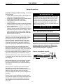
Refer to Figure 2 for an illustration of a typical supply/
return hose kit. Adapters secure hose assemblies to the
unit and risers. Install hose assemblies properly and
check regularly to avoid system failure and reduced
service life.
Table 1: Metal Hose Minimum Bend Radii
Hose Diameter Minimum Bend Radii
1/2" [12.7mm] 2-1/2" [6.4cm]
3/4" [19.1mm] 4" [10.2cm]
1" [25.4mm] 5-1/2" [14cm]
1-1/4" [31.8mm] 6-3/4" [17.1cm]
NOTICE! Do not allow hoses to rest against structural
building components. Compressor vibration may
be transmitted through the hoses to the structure,
causing unnecessary noise complaints.
Figure 2: Supply/Return Hose Kit
Rib Crimped
Length
(2 ft [0.6m] Length Standard)
Swivel
Brass
Fitting
Brass
Fitting
MPT
Reborde Acanalado
Longitud
(Long. Estándar de 2 pies)
Accesorio
Giratorio
de Bronce
Accesorio
de Bronce
MPT
MPT
MPT
Rib Crimped
Length
(0.6m Length Standard)
Swivel
Brass
Fitting
Brass
Fitting
MPT
MPT
Piping Connections
CAUTION! Do not bend or kink supply lines or hoses.
CAUTION!
WARNING! Polyolester Oil, commonly known as POE oil, is
a synthetic oil used in many refrigeration systems including
those with HFC-410A refrigerant. POE oil, if it ever comes
in contact with PVC or CPVC piping, may cause failure of
the PVC/CPVC. PVC/CPVC piping should never be used
as supply or return water piping with water source heat
pump products containing HFC-410A as system failures and
property damage may result.
WARNING!
11

Installation, Operation, Maintenance HRC SERIES Heat Controller
Water-Loop Heat Pump Applications
Commercial Water Loop Applications -
Commercial
systems typically include a number of units connected to
a common piping system. Any unit plumbing maintenance
work can introduce air into the piping system; therefore air
elimination equipment is a major portion of the mechanical
room plumbing. In piping systems expected to utilize water
temperatures below 50°F [10°C], 1/2” (13mm) closed cell
insulation is required on all piping surfaces to eliminate
condensation (extended range units required). Metal to
plastic threaded joints should never be used due to their
tendency to leak over time.
Teon tape thread sealant is recommended to minimize
internal fouling of the heat exchanger. Do not over tighten
connections and route piping so as not to interfere with
service or maintenance access. Hose kits are available
from Heat Controller in different congurations for
connection between the unit and the piping system.
Depending upon selection, hose kits may include shut
off valves, P/T plugs for performance measurement, high
pressure stainless steel braided hose, “Y” type strainer
with blow down valve, and/or “J” type swivel connection.
Balancing valves and an external low pressure drop
solenoid valve for use in variable speed pumping systems
may also be included in the hose kit.
The piping system should be ushed to remove dirt, piping
chips, and other foreign material prior to operation (see
“Piping System Cleaning and Flushing Procedures” in this
manual). The ow rate is usually set between 2.25 and 3.5
gpm per ton [2.9 and 4.5 l/m per kW] of cooling capacity.
Heat Controller recommends 3 gpm per ton [3.9 l/m per
kW] for most applications of water loop heat pumps. To
insure proper maintenance and servicing, P/T ports are
imperative for temperature and ow verication, as well as
performance checks.
Water loop heat pump (cooling tower/boiler) systems
typically utilize a common loop, maintained between 60 -
90°F [16 - 32°C]. The use of a closed circuit evaporative
cooling tower with a secondary heat exchanger between
the tower and the water loop is recommended. If an open
type cooling tower is used continuously, chemical treatment
and ltering will be necessary.
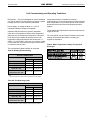
Table 2: Antifreeze Percentages by Volume
Low Water Temperature Cutout Setting - CXM Control
When antifreeze is selected, the LT1 jumper (JW3)
should be clipped to select the low temperature
(antifreeze 10.0°F [-12.2°C]) setpoint and avoid nuisance
faults (see “Low Water Temperature Cutout Selection” in
this manual). Note: Low water temperature operation
requires extended range equipment.
Type
Minimum Temperature for Freeze Protection
10ºF [-12.2ºC] 15ºF [-9.4ºC] 20ºF [6.7ºC] 25ºF [-3.9ºC]
Methanol - 100% USP food grade 25% 21% 16% 10%
Propylene Glycol 38% 30% 22% 15%
12

Heat Controller HRC SERIES Installation, Operation, Maintenance
Pre-Installation -
Prior to installation, locate and mark
all existing underground utilities, piping, etc. Install loops
for new construction before sidewalks, patios, driveways,
and other construction has begun. During construction,
accurately mark all ground loop piping on the plot plan
as an aid in avoiding potential future damage to the
installation.
Piping Installation - All earth loop piping materials
should be limited to polyethylene fusion only for in-ground
sections of the loop. Galvanized or steel ttings should
not be used at any time due to their tendency to corrode.
All plastic to metal threaded ttings should be avoided
due to their potential to leak in earth coupled applications.
A anged tting should be substituted. P/T plugs should
be used so that ow can be measured using the pressure
drop of the unit heat exchanger.
Earth loop temperatures can range between 25 and
110°F [-4 to 43°C]. Flow rates between 2.25 and 3 gpm
per ton [2.41 to 3.23 l/m per kW] of cooling capacity is
recommended in these applications.
Test individual horizontal loop circuits before backlling.
Test vertical U-bends and pond loop assemblies prior to
installation. Pressures of at least 100 psi [689 kPa] should
be used when testing. Do not exceed the pipe pressure
rating. Test entire system when all loops are assembled.
Flushing the Earth Loop - Upon completion of system
installation and testing, ush the system to remove all
foreign objects and purge to remove all air.
CAUTION! The following instructions represent industry
accepted installation practices for closed loop earth coupled
heat pump systems. Instructions are provided to assist the
contractor in installing trouble free ground loops. These
instructions are recommendations only. State/provincial
and local codes MUST be followed and installation MUST
conform to ALL applicable codes. It is the responsibility of
the installing contractor to determine and comply with ALL
applicable codes and regulations.
Ground-Loop Heat Pump Applications
Antifreeze - If any liquid uid or piping is exposed to
unconditioned ambient below 42°F (5.5 C), antifreeze
must be added. If the liquid uid entering the heat pump
is 50°F (10°C) or below, calculate the leaving heat pump
temperature (shown in submittal on performance data
selection notes section). Using the lowest temperature
leaving the heat pump, must protect system 15°F (8°C)
lower. IE: if temperature leaving the heat pump is 35°F
subtract 15°F = 20°F protection required, if Methanol
is used the system would require 16% mix by volume.
Antifreeze is available in alcohol and glycols, contact
local sales ofce for the best type for your system and
area. Following must be considered safety, thermal
performance, corrosiveness, local codes, stability,
convenience, and cost.
All alcohols should be premixed and pumped from
a reservoir outside of the building when possible or
introduced under the water level to prevent fumes.
Calculate the total volume of uid in the piping system.
Then use the percentage by volume shown in table
2 for the amount of antifreeze needed. Antifreeze
concentration should be checked from a well mixed
sample using a hydrometer to measure specic gravity.
CAUTION! Ground loop applications require extended range
equipment and optional refrigerant/water circuit insulation.
Low Water Temperature Cutout Setting - CXM Control
When antifreeze is selected, the LT1 jumper (JW3)
should be clipped to select the low temperature
(antifreeze 10.0°F [-12.2°C]) setpoint and avoid nuisance
faults (see “Low Water Temperature Cutout Selection” in
this manual). Note: Low water temperature operation
requires extended range equipment.
CAUTION!
CAUTION!
13

Installation, Operation, Maintenance HRC SERIES Heat Controller
Open Loop - Ground Water Systems -
Shut off valves
should be included for ease of servicing. Boiler drains or
other valves should be “tee’d” into the lines to allow acid
ushing of the heat exchanger. Shut off valves should
be positioned to allow ow through the coax via the
boiler drains without allowing ow into the piping system.
P/T plugs should be used so that pressure drop and
temperature can be measured. Supply and return water
piping materials should be limited to copper, PE, or similar
material. PVC or CPVC should never be used as they are
incompatible with the POE oils used in HFC-410A products
and piping system failure and property damage may result.
Water quantity should be plentiful and of good quality.
Consult table 2 for water quality guidelines. The unit can
be ordered with either a copper or cupro-nickel water
heat exchanger. Consult Table 2 for recommendations.
Copper is recommended for closed loop systems and open
loop ground water systems that are not high in mineral
content or corrosiveness. In conditions anticipating heavy
scale formation or in brackish water, a cupro-nickel heat
exchanger is recommended. In ground water situations
where scaling could be heavy or where biological growth
such as iron bacteria will be present, an open loop system
is not recommended. Heat exchanger coils may over
time lose heat exchange capabilities due to build up of
mineral deposits. Heat exchangers must only be serviced
by a qualied technician, as acid and special pumping
equipment is required. Desuperheater coils can likewise
become scaled and possibly plugged. In areas with
extremely hard water, the owner should be informed that
the heat exchanger may require occasional acid ushing.
In some cases, the desuperheater option should not be
recommended due to hard water conditions and additional
maintenance required.
Ground-Water Heat Pump Applications
WARNING! Polyolester Oil, commonly known as POE oil, is
a synthetic oil used in many refrigeration systems including
those with HFC-410A refrigerant. POE oil, if it ever comes
in contact with PVC or CPVC piping, may cause failure of
the PVC/CPVC. PVC/CPVC piping should never be used
as supply or return water piping with water source heat
pump products containing HFC-410A as system failures and
property damage may result.
WARNING!
Water Quality Standards -
Table 2 should be consulted
for water quality requirements. Scaling potential should
be assessed using the pH/Calcium hardness method. If
the pH <7.5 and the calcium hardness is less than 100
ppm, scaling potential is low. If this method yields numbers
out of range of those listed, the Ryznar Stability and
Langelier Saturation indecies should be calculated. Use the
appropriate scaling surface temperature for the application,
150°F [66°C] for direct use (well water/open loop) and
DHW (desuperheater); 90°F [32°F] for indirect use. A
monitoring plan should be implemented in these probable
scaling situations. Other water quality issues such as iron
fouling, corrosion prevention and erosion and clogging
should be referenced in Table 2.
Expansion Tank and Pump -
Use a closed, bladder-type
expansion tank to minimize mineral formation due to air
exposure. The expansion tank should be sized to provide
at least one minute continuous run time of the pump using
its drawdown capacity rating to prevent pump short cycling.
Discharge water from the unit is not contaminated in any
manner and can be disposed of in various ways, depending
on local building codes (e.g. recharge well, storm sewer,
drain eld, adjacent stream or pond, etc.). Most local codes
forbid the use of sanitary sewer for disposal. Consult your
local building and zoning department to assure compliance
in your area.
Water Control Valve -
Always maintain water pressure in
the heat exchanger by placing the water control valve(s)
on the discharge line to prevent mineral precipitation
during the off-cycle. Pilot operated slow closing valves are
recommended to reduce water hammer. If water hammer
persists, a mini-expansion tank can be mounted on the
piping to help absorb the excess hammer shock. Insure
that the total ‘VA’ draw of the valve can be supplied by the
unit transformer. For instance, a slow closing valve can
draw up to 35VA. This can overload smaller 40 or 50 VA
transformers depending on the other controls in the circuit.
A typical pilot operated solenoid valve draws approximately
15VA..
14

Heat Controller HRC SERIES Installation, Operation, Maintenance
Ground-Water Heat Pump Applications
Notice! Ground-water applications for commercial
buildings with more than 2-3 units should include
a plate frame heat-exchanger to isolate the heat
pumps from the ground-water and conne heat
exchanger cleanings to one location and lessen
maintenance. Direct use of ground-water may
increase the frequency of heat pump maintenance
and may shorten life expectancy.
Flow Regulation -
Flow regulation can be accomplished
by two methods. One method of ow regulation involves
simply adjusting the ball valve or water control valve on
the discharge line. Measure the pressure drop through the
unit heat exchanger, and determine ow rate. Since the
pressure is constantly varying, two pressure gauges may
be needed. Adjust the valve until the desired ow of 1.5 to
2 gpm per ton [2.0 to 2.6 l/m per kW] is achieved. A second
method of ow control requires a ow control device
mounted on the outlet of the water control valve. The
device is typically a brass tting with an orice of rubber
or plastic material that is designed to allow a specied
ow rate. On occasion, ow control devices may produce
velocity noise that can be reduced by applying some back
pressure from the ball valve located on the discharge line.
Slightly closing the valve will spread the pressure drop over
both devices, lessening the velocity noise.
Note: When
EWT is below 50°F [10°C], 2 gpm per ton (2.6 l/m per
kW) is required.
Water Coil Low Temperature Limit Setting -
For all
open loop systems the 30°F [-1.1°C] LT1 setting (factory
setting-water) should be used to avoid freeze damage to
the unit. See “Low Water Temperature Cutout Selection” in
this manual for details on the low limit setting.
15

Installation, Operation, Maintenance HRC SERIES Heat Controller
Water Quality
Parameter
HX
Material
Closed
Recirculating
Open Loop and Recirculating Well
Scaling Potential - Primary Measurement
pH/Calcium Hardness
All
-
pH < 7.5 and Ca Hardness <100ppm
Method
Index Limits for Probable Scaling Situations - (Operation outside these limits is not recommended)
Ryznar
All
- 6.0 - 7.5
Stability Index If >7.5 minimize steel pipe use.
Langelier
All
-
-0.5 to +0.5
Saturation Index
If <-0.5 minimize steel pipe use. Based upon 66°C HWG and
Direct well, 29°C Indirect Well HX
Iron Fouling
Iron Fe
2+
(Ferrous)
All
-
<0.2 ppm (Ferrous)
(Bacterial Iron potential)
If Fe
2+
(ferrous)>0.2 ppm with pH 6 - 8, O2<5 ppm check for iron bacteria.
Iron Fouling
All
-
<0.5 ppm of Oxygen
Above this level deposition will occur .
Corrosion Prevention
pH
All
6 - 8.5
6 - 8.5
Monitor/treat as
needed
Minimize steel pipe below 7 and no open tanks with pH <8
Hydrogen Sulfide (H
2
S)
All
- <0.5 ppm
At H
2
S>0.2 ppm, avoid use of copper and copper nickel piping or HX's.
Rotten egg smell appears at 0.5 ppm level.
Copper alloy (bronze or brass) cast components are OK to <0.5 ppm.
Ammonia ion as hydroxide, chloride,
nitrate and sulfate compounds
All
-
<0.5 ppm
Maximum
Maximum Allowable at maximum water temperature.
Chloride Levels
10°C 24°C 38
C
Copper
Cupronickel
- <20ppm NR NR
- <150 ppm NR NR
304 S
S - <400 ppm <250 ppm <150 ppm
316 S
S - <1000 ppm <550 ppm < 375 ppm
Titanium - >1000 ppm >550 ppm >375 ppm
Erosion and Clogging
Particulate Size and
Erosion
All
<10 ppm of particles
and a maximum
velocity of 1.8 m/s
Filtered for maximum
841 micron [0.84 mm,
20 mesh] size.
<10 ppm (<1 ppm "sandfree” for reinjection) of particles and a maximum
velocity of 1.8 m/s. Filtered for maximum 841 micron 0.84 mm,
20 mesh] size. Any particulate that is not removed can potentially
clog components.
Notes:
Rev.: 5/6/2014 S
• NR - Application not recommended.
• "-" No design Maximum.
• Closed Recirculating system is identified by a
closed pressurized piping system.
• Recirculating open wells should observe the open recirculating design considerations.
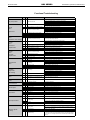
Above the given limits, scaling is likely to occur. Scaling indexes should be calculated using the limits below
Scaling indexes should be calculated at 66°C for direct use and HWG applications, and at 32°C for indirect HX use.
A monitoring plan should be implemented.
The Heat Controller Water Quality Table provides water quality requirements for Heat Controller coaxial heat exchangers. The water should be evaluated by an
independent testing facility comparing to this Table and when properties are outside of these requirements, an external secondary heat exchanger must be used to
isolate the heat pump heat exchanger from the unsuitable water. Failure to do so will void the warranty for the coaxial heat exchanger and any other components
damaged by a leak.
Water Quality Standards
Table 2: Water Quality Standards
16

Heat Controller HRC SERIES Installation, Operation, Maintenance
Electrical - Line Voltage
Electrical - Line Voltage -
All eld installed wiring,
including electrical ground, must comply with the National
Electrical Code as well as all applicable local codes.
Refer to the unit electrical data for fuse sizes. Consult
wiring diagram for eld connections that must be made
by the installing (or electrical) contractor. All nal electrical
connections must be made with a length of exible conduit
to minimize vibration and sound transmission to the
building.
WARNING! To avoid possible injury or death due to electrical
shock, open the power supply disconnect switch and secure
it in an open position during installation.
CAUTION! Use only copper conductors for eld installed
electrical wiring. Unit terminals are not designed to accept
other types of conductors.
General Line Voltage Wiring -
Be sure the available
power is the same voltage and phase shown on the unit
serial plate. Line and low voltage wiring must be done in
accordance with local codes or the National Electric Code,
whichever is applicable.
Power Connection -
Line voltage connection is made by
connecting the incoming line voltage wires to the “L” side
of the contactor. Consult Tables 4 through 5 for correct
fuse size.
Transformer -
All commercial dual voltage units are
factory wired for 208/60/1. If supply voltage is 230/60/1,
installer must rewire transformer. See wire diagram for
connections.
CAUTION!
WARNING!
17
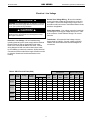
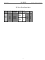
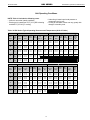
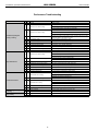
Table 4: HRC Electrical Data (60Hz)
Standard Unit With Secondary Pump
Model
Voltage
Code
Voltage
Min/Max
Voltage
Compressor
Fan
Motor
FLA
Total
Unit
FLA
Min
Circuit
Amps
Max
Fuse/
HACR
Total
Unit
FLA
Min
Circuit
Amps
Max
Fuse/
HACR
QTY RLA LRA
HRC09
0 115/60/1 104-126 1 8.0 46.5 0.5 8.5 10.5 20 8.8 11.3 20
1 208-230/60/1 197-254 1 4.5 23.0 0.4 4.9 6.0 15 5.3 6.4 15
8 265/60/1 239-292 1 5.0 19.0 0.4 5.4 6.7 15 6.2 7.5 15
HRC12
0 115/60/1 104-126 1 9.5 50.0 0.5 10.0 12.4 20 11.5 13.8 20
1 208-230/60/1 197-254 1 4.7 25.0 0.6 5.3 6.5 15 5.7 7.3 15
8 265/60/1 239-292 1 4.2 22.0 0.4 4.6 5.7 15 5.4 6.5 15
HRC15
1 208-230/60/1 197-254 1 5.6 30.0 0.8 6.4 7.8 15 7.2 8.6 15
8 265/60/1 239-292 1 4.7 28.5 0.6 5.3 6.5 15 6.2 7.3 15
HRC18
1 208-230/60/1 197-254 1 6.8 38.0 0.7 7.5 9.2 15 8.3 10.0 15
8 265/60/1 239-292 1 6.2 29.0 0.6 6.8 8.4 15 7.6 9.2 15

Installation, Operation, Maintenance HRC SERIES Heat Controller
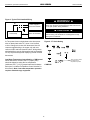
LT1
LT2
LT 1
LT 1
LT 2
LT 2
Figure 4: LT1 Limit Setting
CXM PCB
JW3-LT1 jumper should
be clipped for low
temperature operation
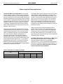
Field Supplied
Disconnect Switch
Heat Pump
A
Room Thermostat
B
A= Two power wires on single-phase units: three power
wires on three-phase units. B= 1 heat /1 cool /manual
or Auto Change-over remote 24V thermostat. Note: All
customer-supplied wiring to be copper only and must
conform to NEC and local electrical codes. Wiring shown
with dashed lines must be eld-supplied and eld-installed.
"B" only required with systems employing remote mounted
thermostats.
Figure 3: Typical Field Installed Wiring
WARNING! To avoid possible injury or death due to electrical
shock, open the power supply disconnect switch and secure
it in an open position during installation.
CAUTION! Use only copper conductors for eld installed
electrical wiring. Unit terminals are not designed to accept
other types of conductors.
Low Water Temperature Cutout Setting - CXM Control
When antifreeze is selected, the LT1 jumper (JW3)
should be clipped to select the low temperature
(antifreeze 10.0°F [-12.2°C]) setpoint and avoid nuisance
faults (see “Low Water Temperature Cutout Selection” in
this manual). Note: Low water temperature operation
requires extended range equipment.
CAUTION!
WARNING!
18

Heat Controller HRC SERIES Installation, Operation, Maintenance
19
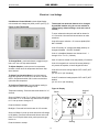
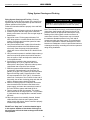
Unit-Mounted Control Models
include digital display
unit-mounted auto changeover (ACO) control. (see Fig. 5).
To Change Mode
- push mode button to toggle through
heat, cool, auto, off. Stop where desired.
To Adjust Setpoint
- push up arrow for temperature
increase or down arrow for temperature decrease. Stop
where desired.
To Select Fan Operation/Speed
- push fan button to
toggle through fan on low, fan on hi, fan auto lo, and fan
auto hi. Stop where desired. ON is continuous and Auto
cycles fan with compressor.
To Congure Thermostat
- for temperature reading in
Fahrenheit or Celsius and backlight on/off.
Temperature reading - Press and hold mode button for 3-5
seconds.
Screen will ash U1 with ºF or ºC below. Press and release
mode button ºF or ºC will ash. Use down arrow to change
to ºC. Use up arrow to change to ºF.
Press fan button to escape.
Backlight - Press and hold mode button for 3-5 seconds.
Screen will ash U1 press up arrow and screen will change
to U2 ashing. Press and release mode button and on will
ash. To turn off push down arrow, push up arrow to get
back to on.
Press fan button to escape.
Figure 5: ACO Thermostat
Figure 6: Display
Electrical - Low Voltage
Thermostat has advanced features to be changed
by qualied installer only (do not use code 99- to
restore factory default settings, reset each code if
needed.)
To enter advanced mode push and hold fan button for
10-15 seconds. Use mode and arrow buttons to make
selections.
Code 02 is sensor selection : rS is remote (default) DO
NOT CHANGE.
Code 07 is delay: off - timeguard enabled (default); on-
timeguard disabled. DO NOT CHANGE.
Code 11 is deadband between auto heat and cool: 1
through 10 for ºF or ºC ( 5 default).
Code 15 is auto or manual: On is auto (default); of is manual.
Code 21 is keypad lock: user has full access (default); 1
only access to setpoints; cd entire keypad is locked.
Code 26 is minimum cooling setpoint: 55ºF to 90ºF (60ºF
default).
[12 ºC to 32 ºC (50 ºC default)]
Code 27 is maximum heating setpoint: 50ºF to 90ºF (85ºF
default).
[10 ºC to 32 ºC (29 ºC default)]
actual temp
set at
ºF
heat
fan
on
keypad
lock
Mode
Fan Setting

Installation, Operation, Maintenance HRC SERIES Heat Controller
Wire Size Maximum Wire Length*
18-Gauge 75 feet [22m]
16-Gauge 125 feet [38m]
14-Gauge 200 feet [60 m]
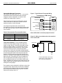
Figure 7a: Wiring for multiple units to be controlled
from 1 thermostat
Thermostat Installation -
The thermostat should be
located on an interior wall in a larger room, away from
supply air drafts. DO NOT locate the thermostat in areas
subject to sunlight, drafts or on external walls. The wire
access hole behind the thermostat may in certain cases
need to be sealed to prevent erroneous temperature
measurement. Position the thermostat back plate against
the wall so that it appears level and so the thermostat wires
protrude through the middle of the back plate. Mark the
position of the back plate mounting holes and drill holes
with a 3/16” (5mm) bit. Install supplied anchors and secure
plate to the wall. Thermostat wire must be 18 AWG wire.
Wire the appropriate thermostat as shown in Figure 7 to
the low voltage terminal strip on the CXM or DXM control
board. Practically any heat pump thermostat will work with
Heat Controller units, provided it has the correct number of
heating and cooling stages.
Zone integrity must be maintained to efciently control units
or groups of units. Unless zones of control are considered
and accounted for, adjacent units may operate in heating
and cooling modes simultaneously, to prevent units with
DXM can be wired per gure 7A.
*Length = Physical distance from thermostat to unit.
Table 6: Recommended Thermostat Wire Sizes
Figure 7: Typical Remote Thermostat Wiring
Thermostat
Connection to CXM Control
Compressor
Reversing Valve
Fan
24Vac Hot
24Vac Common
Fault LED
Y
O
G
R
C
L
Y
O
G
R
C
AL1
CXM
Optional Wall-Mounted Thermostat
HRC WSHP units (Model digit 8 is C, D, F, or K) are built
with standard internal thermostat that has automatic
changeover (ACO) conguration. No external, eld-
installed low-voltage wiring is required.
When desired, the unit can be furnished with a 24-volt
control circuit which is eld-wired to a Heat Controller-
supplied accessory remote thermostat.
Low-voltage wiring between the unit and the wall
thermostat must comply with all applicable electrical codes
(i.e., NEC and local codes), and be completed before the
unit is installed.
Note: If ATA11U03 is used must jumper G and G2
CS
DXM
Unit
1
Connect thermostat to Unit 1 then
jumper Com 1 (S to S and C to C)
up to 6 units with twisted pair.
DXM
Unit
2-6
Thermostat
CS
20
Page is loading ...
Page is loading ...
Page is loading ...
Page is loading ...
Page is loading ...
Page is loading ...
Page is loading ...
Page is loading ...
Page is loading ...
Page is loading ...
Page is loading ...
Page is loading ...
Page is loading ...
Page is loading ...
Page is loading ...
Page is loading ...
Page is loading ...
Page is loading ...
Page is loading ...
Page is loading ...
-
 1
1
-
 2
2
-
 3
3
-
 4
4
-
 5
5
-
 6
6
-
 7
7
-
 8
8
-
 9
9
-
 10
10
-
 11
11
-
 12
12
-
 13
13
-
 14
14
-
 15
15
-
 16
16
-
 17
17
-
 18
18
-
 19
19
-
 20
20
-
 21
21
-
 22
22
-
 23
23
-
 24
24
-
 25
25
-
 26
26
-
 27
27
-
 28
28
-
 29
29
-
 30
30
-
 31
31
-
 32
32
-
 33
33
-
 34
34
-
 35
35
-
 36
36
-
 37
37
-
 38
38
-
 39
39
-
 40
40


Century HRC12A8RAMSCFL Installation, Operation & Maintenance Manual
- Category
- Heat pumps
- Type
- Installation, Operation & Maintenance Manual
- This manual is also suitable for
Ask a question and I''ll find the answer in the document
Finding information in a document is now easier with AI
Related papers
-
COMFORT-AIRE HRC09A1RAMSCFL Operating instructions
-
-
COMFORT-AIRE HNW036A1C00NFC-CY Operating instructions
-
COMFORT-AIRE CMA1448SF-1 Operating instructions
-
COMFORT-AIRE CMA1418SG-1 Operating instructions
-
-
COMFORT-AIRE HZD048B1D00CLN User guide
-
COMFORT-AIRE HBV060A3C30CRT-CY Installation guide
-
-
Other documents
-
Premier Copper Products SB1 Dimensions Guide
-
ClimateMaster CXM Controls Install Manual
-
-
-
 General Air Products LT900150A Installation guide
-
-
-
Bosch Thermotechnology 7735032303 User guide
-
Greenheck 913836 Remote Condensing Unit Operating instructions
-
