
(English)
DM-BR0008-10
ST-RS505
ST-RS685
BR-RS505
BR-RS785
BR-RS805
Dealer's Manual
ROAD MTB Trekking
City Touring/
Comfort Bike
URBAN SPORT E-BIKE
Hydraulic Disc Brake/
DUAL CONTROL LEVER
This manual does not cover the assembly of ST-R785 with brakes.
For the assembly of ST-R785 with brakes, refer to “DM-BR0004”.

2
CONTENTS
IMPORTANT NOTICE .............................................................................................. 3
TO ENSURE SAFETY ............................................................................................... 4
LIST OF TOOLS TO BE USED ................................................................................ 10
INSTALLATION ..................................................................................................... 12
Installation of the brake hose ...................................................................................................................12
Installation of the brake hose (easy hose joint system) ........................................................................... 18
Installation to the handlebar ....................................................................................................................24
Adding Shimano genuine mineral oil and bleeding air ..........................................................................26
Installing the brake caliper ........................................................................................................................ 41
Temporary tightening of the frame fixing bolts ......................................................................................52
Installing the shifting cable .......................................................................................................................53
ADJUSTMENT ...................................................................................................... 62
Free stroke and reach adjustment ............................................................................................................62
MAINTENANCE .................................................................................................... 67
Replacing the brake pads ..........................................................................................................................67
Replacement of the nameplate .................................................................................................................69
Shimano genuine mineral oil replacement ..............................................................................................70
Replacing the bracket cover ......................................................................................................................70
Replacing the main lever support .............................................................................................................72
Replacing the cable cover .......................................................................................................................... 74
How to pull out a disconnected inner end (shifting cable) .....................................................................75
Replacement of the SL cable guide ...........................................................................................................78

3
IMPORTANT NOTICE
IMPORTANT NOTICE
•
This dealer’s manual is intended primarily for use by professional bicycle mechanics.
Users who are not professionally trained for bicycle assembly should not attempt to install the components themselves using the dealer’s manuals.
If any part of the information on the manual is unclear to you, do not proceed with the installation. Instead, contact your place of purchase or a local
bicycle dealer for their assistance.
•
Make sure to read all instruction manuals included with the product.
•
Do not disassemble or modify the product other than as stated in the information contained in this dealer’s manual.
•
All dealer’s manuals and instruction manuals can be viewed on-line on our website (https://si.shimano.com).
•
For consumers who do not have easy access to the internet, please contact a SHIMANO distributor or any of the SHIMANO offices to obtain a hardcopy
of the User's Manual.
•
Please observe the appropriate rules and regulations of the country, state or region in which you conduct your business as a dealer.
For safety, be sure to read this dealer’s manual thoroughly before use, and follow it for correct use.
The following instructions must be observed at all times in order to prevent personal injury and physical damage to equipment and surroundings.
The instructions are classified according to the degree of danger or damage which may occur if the product is used incorrectly.
DANGER
Failure to follow the instructions will result in death or serious injury.
WARNING
Failure to follow the instructions could result in death or serious injury.
CAUTION
Failure to follow the instructions could cause personal injury or physical damage to equipment and surroundings.

4
TO ENSURE SAFETY
TO ENSURE SAFETY
WARNING
•
When installing components, be sure to follow the instructions that are given in the instruction manuals.
It is recommended that you use only genuine Shimano parts. If parts such as bolts and nuts become loose or damaged, the bicycle may suddenly fall
over, which may cause serious injury.
In addition, if adjustments are not carried out correctly, problems may occur, and the bicycle may suddenly fall over, which may cause serious injury.
•
Be sure to wear safety glasses or goggles to protect your eyes while performing maintenance tasks such as replacing parts.
•
After reading the dealer's manual thoroughly, keep it in a safe place for later reference.
Be sure to also inform users of the following:
Brake
•
Each bicycle may handle slightly differently depending on the model. Therefore, be sure to learn the proper braking technique (including brake lever
pressure and bicycle control characteristics) and operation of your bicycle. Improper use of your bicycle's brake system may result in a loss of control or
a fall, which could lead to severe injury. For proper operation, consult your professional bicycle dealer or the bicycle's owner's manual. It is also
important to practice riding as well as braking operation, etc.
•
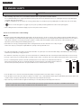
Please make sure to keep your fingers away from the rotating disc brake rotor. The disc brake rotor is sharp enough to
inflict severe injury to your fingers if caught within the openings of moving disc brake rotor.
•
The calipers and disc brake rotor will become hot when the brakes are operated; do not touch them while riding or immediately after dismounting
from the bicycle. Otherwise you may get burned.
•
Be careful not to allow any oil or grease to get onto the disc brake rotor and brake pads. There is the danger that the brakes may not work correctly.
•
If any oil or grease does get on the brake pads, you should consult a dealer or an agency. There is the danger that the brakes may not work correctly.
•
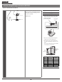
If noise occurs during brake operation, the brake pads may have been worn down to the usable limit. Check that the
brake system temperature has been cooled down sufficiently, check the thickness of the brake pad. If the thickness is
0.5 mm or below, the brake pad needs to be replaced with a new one. Consult a dealer or an agency.
2 mm 0.5 mm
•
If the disc brake rotor is cracked or deformed, immediately stop using the brakes and consult a dealer or an agency.
•
If the disc brake rotor becomes worn down to a thickness of 1.5 mm or less, or if the aluminum surface appears, immediately stop using the brakes and
consult a dealer or an agency. The disc brake rotor may break, and you may fall off the bicycle.
•
Vapor lock may occur if the brakes are applied continuously. To solve this problem, momentarily release the lever.
Vapor lock is a phenomenon in which the oil inside the brake system becomes heated, which causes any water or air bubbles inside the brake
system to expand. This can then result in a sudden increase in the brake lever stroke.

5
TO ENSURE SAFETY
•
The disc brake is not designed to work when the bicycle is upside down. If the bicycle is turned upside down or on its side, the brake may not work
correctly, and a serious accident could occur. Before riding the bicycle, be sure to operate the brake lever a few times to check that the brakes operate
normally. If the brakes do not operate normally, stop using the brakes and consult a dealer or an agency.
•
If you feel no resistance when depressing the brake lever, immediately stop using the brakes and consult a dealer or an agency.
•
If fluid leaks occur, immediately stop using the brakes and consult a dealer or an agency.
•
If the front brake is applied too strongly, the wheel may lock and the bicycle may fall forward, and serious injury may result.
•
Always make sure that the front and rear brakes are working correctly before riding the bicycle.
•
The required braking distance will be longer during wet weather. Reduce your speed and apply the brakes early and gently.
•
If the road surface is wet, the tires will skid more easily. If the tire skids, the bicycle may fall over, resulting in danger. Reduce your speed and apply the
brakes early and gently.
•
The lever should never be altered. Otherwise, the lever may break, and braking may become disabled.
•
Check before riding that there is no damage such as carbon peeling or cracking. If there is any damage, stop using the bicycle and consult a dealer or
an agency. Otherwise, the lever may break, and braking may become disabled.
For Installation to the Bicycle, and Maintenance:
•
Please make sure to keep your fingers away from the rotating disc brake rotor during installation or maintenance of the
wheel.
The disc brake rotor is sharp enough to inflict severe injury to your fingers if caught within the openings of moving disc
brake rotor.
•
If the disc brake rotor is worn, cracked or warped, it should be replaced.
•
If the disc brake rotor becomes worn down to a thickness of 1.5 mm or so that the aluminum surface becomes visible, be sure to replace the disc brake
rotor with a new one.
•
Check that the brake components have cooled down sufficiently before attempting to adjust the brakes.
•
Use only Shimano genuine mineral oil. If other types of oil are used, it may cause problems with brake operation, and cause the system to be
unuseable.
•
Be sure to use only oil from a freshly-opened container, and do not re-use oil which has been drained from the bleed nipple. Old or reused oil may
contain water, which could cause vapor lock in the brake system.
•
Be careful not to let water or air bubbles get into the brake system. Otherwise, vapor lock may occur. Be particularly careful when removing the cover
of the reservoir tank.
•
If cutting the brake hose in order to adjust the length of the hose, or when changing over the brake hose from left to right or vice versa, be sure to
bleed the air from the hose according to steps given in “Adding Shimano genuine mineral oil and bleeding air”.
•
When turning the bicycle upside down or on its side, the brake system may have some air bubbles inside the reservoir tank which are still there when
the bleed screw is closed, or which accumulate in various parts of the brake system when it is used for long periods. This disc brake system is not
designed to work with the bicycle upside down. If the bicycle is turned upside down or on its side, the air bubbles inside the reservoir tank may move
in the direction of the calipers. If the bicycle has been turned upside down or on its side, be sure to operate the brake lever a few times to check that
the brakes operate normally before riding the bicycle. If the brakes do not operate normally, adjust them according to the following procedure.
If brake does not seem to work (feels sluggish) when the lever is depressed
Set the bleed section of the brake lever so that it is parallel to the ground, and then gently depress the brake lever several times and wait for the
bubbles to return to the reservoir tank.
If the brakes still operate sluggishly, bleed the air from the brake system. (Refer to "Adding Shimano genuine mineral oil and bleeding air")

6
TO ENSURE SAFETY
•
If the quick release lever on the hub is on the same side as the disc brake rotor, they may interfere with each other, which is dangerous, so check that
they do not.
•
Shimano disc brake systems are not compatible with tandem bicycles. Because tandem bicycles are heavier, the stress on the brake system increases
during brake operation. If hydraulic disc brakes are used with tandem bicycles, the oil temperature will become too high and vapor locks or ruptures
in the brake hoses may occur, and this will cause the brakes to fail.
•
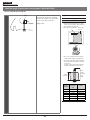
When installing the brake caliper using bolt fixing pins, be sure to use mounting bolts of the
appropriate length.
If not, the bolt fixing pins may not be securely fastened, and the bolts may fall out.
Bolt fixing pin
Brake hose
•
After installing the brake hose to the brake unit, adding Shimano genuine mineral oil and bleeding air bubbles, depress the lever again several times
to check that the brakes are operating normally and there are no fluid leaks from the hose or the system.
•
The connector insert is for this brake hose only. Use an appropriate connector insert according to the following table. Use of a connector insert
incompatible with the brake hose may cause fluid leaks.
Model No. Length Color
SM-BH59-JK-SS 13.2 mm Gold
•
Do not reuse the olive piece or the connector insert when reinstalling. A damaged or reused olive or the connector insert may not provide secure
brake hose connection, possibly causing the brake hose to disconnect from the brake calipers or brake lever.
If the brake hose becomes disconnected, there is danger that the brakes may suddenly stop working.
Brake hose
Connecting bolt
Olive
Cut end
Connector insert
•
Cut the brake hose so that the cut end is perpendicular to the length of the hose. If the brake hose is cut at an angle, fluid leaks may result.
90 degrees

7
TO ENSURE SAFETY
CAUTION
Be sure to also inform users of the following:
Cautions on the Shimano genuine mineral oil
•
Contact with eyes may result in irritation. In the event of contact with eye, wash with water and seek medical attention immediately.
•
Contact with skin may cause a rash and discomfort. In the event of contact with skin, wash well with soap and water.
•
Inhalation of Shimano genuine mineral oil mist or vapors may cause nausea. Cover nose and mouth with a respirator type mask and use in a well
ventilated area. If Shimano genuine mineral oil vapor is inhaled, go immediately to an area with fresh air and cover up with a blanket. Lay down and
keep warm, and seek professional medical attention if required.
Burn-in period
•
Disc brakes have a burn-in period, and the braking force will gradually increase as the burn-in period progresses. Make sure that you are aware of any
such increases in braking force when using the brakes during the burn-in period.
For Installation to the Bicycle, and Maintenance:
Handling the Shimano genuine mineral oil
•
Contact with eyes may result in irritation. Use safety glasses when handling, and avoid contact with eyes.
In the event of contact with eye, wash with water and seek medical attention immediately.
•
Contact with skin may cause a rash and discomfort. Use gloves when handling.
In the event of contact with skin, wash well with soap and water.
•
Do not drink. May cause vomiting or diarrhea.
•
Keep out of reach of children.
•
Do not cut, let near heat, weld or pressurize the oil container, as this may cause explosion or fire.
•
Disposal of Used Oil: Follow local county and/or state codes for disposal.
•
Directions: Keep the container sealed to prevent foreign objects and moisture from getting inside, and store it in a cool, dark area away from direct
sunlight or heat.
Keep from heat or flame. Petroleum Class III, Danger level III
When cleaning with a compressor
•
If disassembling the caliper body to clean the internal parts using a compressor, note that moisture from the compressed air may remain on the caliper
components. Let the caliper components dry sufficiently before reassembling the calipers.
Brake hose
•
When cutting the brake hose, handle the knife carefully so as not to cause injury.
•
Be careful to avoid injury from the olive.

8
TO ENSURE SAFETY
NOTICE
Be sure to also inform users of the following:
•
Be sure to keep turning the crank during the gear shifting.
•
Handle the products carefully, and avoid subjecting them to any strong shocks.
•
Do not use thinners or similar substances to clean the products. Such substances may damage the surfaces.
•
In the case of carbon levers, wash them with a soft cloth using a neutral detergent. Otherwise, the material may get damaged, and the strength may
be affected.
•
Avoid leaving the carbon levers in places where high temperatures are present. Also, keep them far away from fire.
•
If gear shifting operations do not feel smooth, wash the derailleur and lubricate all moving parts.
•
When the bicycle wheel has been removed, it is recommended that pad spacers are installed. Do not depress the brake lever while the wheel is
removed. If the brake lever is depressed without the pad spacers installed, the pistons will protrude further than normal. If that happens, consult a
dealer.
•
Use soapy water and a dry cloth when cleaning and carrying out maintenance of the brake system. Do not use commercially available brake cleaners
or silencing agents, as they can cause damage to parts such as seals.
•
Products are not guaranteed against natural wear and deterioration from normal use and aging.
•
For maximum performance we highly recommend Shimano lubricants and maintenance products.
For Installation to the Bicycle, and Maintenance:
•
Use a brake hose / outer casing which still has some length to spare even when the handlebars are turned all the way to both sides. Furthermore,
check that the shifting lever does not touch the bicycle frame when the handlebars are turned all the way.
•
Use an OT-SP cable and cable guide for smooth operation.
•
Grease the inner cable and the inside of the outer casing before use to ensure that they slide properly. Do not let dust adhere on the inner cable. If
the grease on the inner cable is wiped off, the application of SIS SP41 grease (Y04180000) is recommended.
•
A special grease is used for the gear shifting cable. Do not use premium grease or other types of grease, otherwise they may cause deterioration in
gear shifting performance.
•
If gear shifting adjustments cannot be carried out, check that the rear fork ends are aligned. Also check if the cable is lubricated and if the outer
casing is too long or too short.
•
Do not remove the lever unit.
Disc brake
•
If the brake caliper mounting boss and the dropout are not of standard dimensions, the disc brake rotor and caliper may touch.
•
When the bicycle wheel has been removed, it is recommended that pad spacers are installed. The pad spacers will prevent the piston from coming out
if the brake lever is depressed while the wheel is removed.
•
If the brake lever is depressed without the pad spacers installed, the pistons will protrude further than is normal. Use a slotted screwdriver or similar
tool to push back the brake pads, while being careful not to damage the surfaces of the brake pads. (If the brake pads are not installed, use a
flat-shaped tool to push the pistons straight back in, while being careful not to damage them)
If it is difficult to push the brake pads or pistons back, remove the bleed screws and then try again. (Note that some oil may overflow from the
reservoir tank at this time.)
•
Use isopropyl alcohol, soapy water or a dry cloth when cleaning and carrying out maintenance of the brake system. Do not use commercially available
brake cleaners or silencing agents. They can cause damage to parts such as seals.
•
Do not remove the pistons when disassembling the brake calipers.
•
If the disc brake rotor is worn, cracked or warped, it should be replaced.
The actual product may differ from the illustration because this manual is intended chiefly to explain the procedures for using
the product.

LIST OF TOOLS TO BE USED

LIST OF TOOLS TO BE USED
10
LIST OF TOOLS TO BE USED
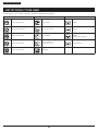
The following tools are needed for installation, adjustment, and maintenance purposes.
Tool Tool Tool
2 mm hexagon wrench 8 mm spanner TL-BH61
2.5 mm hexagon wrench 7 mm socket wrench TL-CT12
3 mm hexagon wrench Screwdriver[#1]
SM-DISC
(Oil funnel and oil stopper)
4 mm hexagon wrench
Slotted screwdriver
(nominal dia. 0.8 × 4)
TL-BT03/TL-BT03-S
5 mm hexagon wrench Utility knife

INSTALLATION

INSTALLATION
Installation of the brake hose
12
To be continued on next page
INSTALLATION
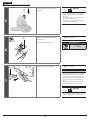
Installation of the brake hose
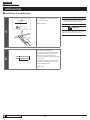
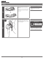
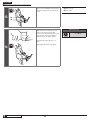
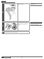
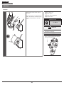
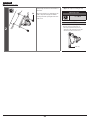
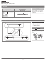
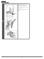
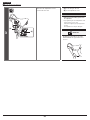
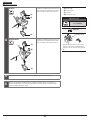
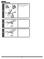
1
(z)
Use a utility knife or other cutting tool
to cut the brake hose.
(z)
90 degrees
NOTICE
Use the utility knife safely and correctly in
accordance with its instruction manual.
TECH TIPS
If you are using TL-BH62, refer to the Service
instruction accompanying the product.
2
(z)
Put a mark on the brake hose
beforehand as shown in the illustration
so that you can check if the ends of the
brake hose are secured to the hose
mounts of the brake caliper and the dual
control lever.
(As a guide, the length of the portion of
the brake hose that is inside the mount
is approximately 11 mm.)
(z)
11 mm

INSTALLATION
Installation of the brake hose
13
To be continued on next page
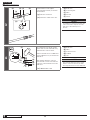
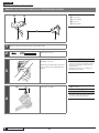
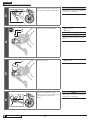
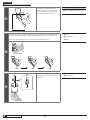
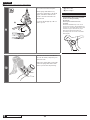
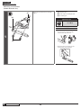
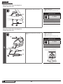
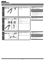
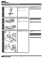
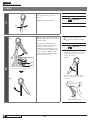
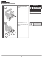
3
(D)(C)(B)(A)
(C)(E)
(z)
(y)
Pass the brake hose through the
connecting bolt and olive, as shown in
the illustration.
(y)
Direction of insertion
(z)
Grease the outside of the olive.
(A) Brake hose
(B) Connecting bolt
(C) Olive
(D) Cut end
(E) Grease
NOTICE
For installation to the built-in type frame, first
connect to the frame caliper the end of the
brake hose to which the banjo is not
attached.
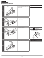
4
(A) (C)
(A)
(B)
(D)
(E)
(z)
(C)
Use a tapered tool to smooth out the
inside of the cut end of the brake hose,
and mount the connector insert.
Connect the brake hose to TL-BH61 and
secure TL-BH61 in a vise, as shown in the
illustration.
Then, hammer down the connector
insert until the connector insert mount
comes into contact with the end of the
brake hose.
(z)
SM-BH59-JK-SS: 1 mm
(A) Brake hose
(B) Olive
(C) Connector insert
(D) TL-BH61
(E) Vise
NOTICE
If the end of the brake hose is not in contact
with the connector insert mount, the brake
hose may be disconnected or cause fluid leaks.

INSTALLATION
Installation of the brake hose
14
To be continued on next page
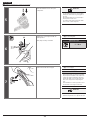
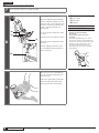
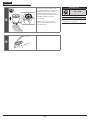
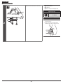
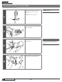
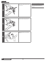
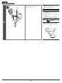
5
(A) (B) (C)
(z)
After checking that the olive is
positioned as shown in the illustration,
grease the screw threads of the
connecting bolt.
(z)
2 mm
(A) Brake hose
(B) Olive
(C) Connector insert
NOTICE
Use the dedicated connector insert supplied
with SM-BH59-JK-SS.
Use of any connector insert other than the
one supplied may produce a loose assembly,
leading to oil leaks or other problems.
Model No. Length Color
SM-BH59-JK-SS 13.2 mm Gold

INSTALLATION
Installation of the brake hose
15
To be continued on next page
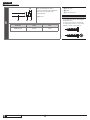
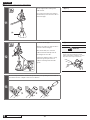
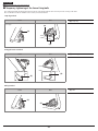
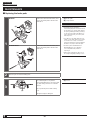
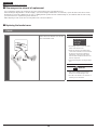
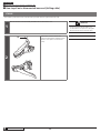
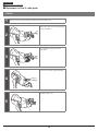
6
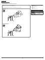
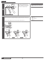
Make sure that the brake hose is not twisted.
Make sure that the brake calipers and dual control levers are in the positions shown in the
illustrations.
(y)
Left lever
(z)
Right lever
(A) Brake caliper
ST-RS685/BR-RS785
(y)
(A)
(z)
(A)
ST-RS505/BR-RS805, BR-RS505
(y)
(z)

INSTALLATION
Installation of the brake hose
16
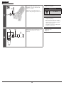
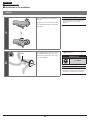
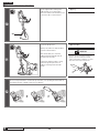
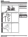
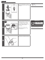
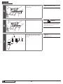
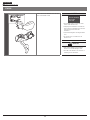
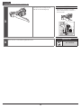
7
(A)
Secure the dual control lever to the
handlebar or in a vise and insert the
brake hose straight.
Tighten the connecting bolt with a
spanner while pushing the brake hose.
(A) Connecting bolt
Tightening torque
5 - 7 N·m
NOTICE
•
At this point, make sure the brake hose is
straight when pushing.
•
When installing the brake hose with the
dual control lever secured to the handlebar,
adjust the angle of the bracket to make it
easier to turn the spanner.
At that time, be careful not to damage the
handlebar and other parts.
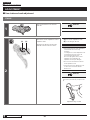
8
(B) (A)
Temporarily secure the brake hose to the
handlebar (by using tape or similar
material).
(A) Brake hose
(B) Tape

INSTALLATION
Installation of the brake hose
17
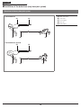
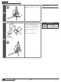
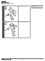
End of the brake hose on the brake caliper side
Attach the connector insert to the brake hose.
After that, while pushing the brake hose, tighten the connecting bolt.
(A) Brake hose
(B) Connecting bolt
(C) Olive
(D) Connector insert
Tightening torque
5 - 7 N·m
BR-RS785
(A) (B) (C) (D)
BR-RS805/BR-RS505
(A) (B) (C) (D)

INSTALLATION
Installation of the brake hose (easy hose joint system)
18
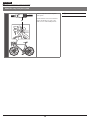
Installation of the brake hose (easy hose joint system)
Overview of the easy hose joint system
ST-RS685/BR-RS785
(A)
(D)
(C)
(E)
(B)
ST-RS505/BR-RS805, BR-RS505
(A)
(D)
(C)
(E)
(B)
(A) Dual control lever
(B) Joint sleeve
(C) Lever stopper
(D) Hose cap
(E) Brake caliper

INSTALLATION
Installation of the brake hose (easy hose joint system)
19
About the easy hose joint system
(A)
This is a component of the easy hose
joint system.
For information on how to install and
replace the brake hose, refer to the
brake section of General Operations.
(A) Joint sleeve

INSTALLATION
Installation of the brake hose (easy hose joint system)
20
To be continued on next page
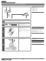
About the easy hose joint system (Direct) (ST-RS685/BR-RS785)
(A) (B)
(D)(C) (E)
(A) Dual control lever
(B) Joint sleeve
(C) Lever stopper
(D) Hose cap
(E) Brake caliper
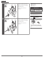
1
Pass the brake hose through each hole in the built-in frame.
2
Remove the hose cap.
3
Secure the dual control lever to the
handlebar or in a vise.
At this time, point the dual control lever
hose connection port upward and fix it
in place.
NOTICE
When installing the brake hose with the dual
control lever secured to the handlebar, adjust
the angle of the bracket to make it easier to
turn the spanner.
At that time, be careful not to damage the
handlebar and other parts.
4
(A)
Remove the seal plug.
(A) Seal plug
NOTICE
Cover the seal plug with a waste cloth as the
oil applied to the seal plug may leak.
Page is loading ...
Page is loading ...
Page is loading ...
Page is loading ...
Page is loading ...
Page is loading ...
Page is loading ...
Page is loading ...
Page is loading ...
Page is loading ...
Page is loading ...
Page is loading ...
Page is loading ...
Page is loading ...
Page is loading ...
Page is loading ...
Page is loading ...
Page is loading ...
Page is loading ...
Page is loading ...
Page is loading ...
Page is loading ...
Page is loading ...
Page is loading ...
Page is loading ...
Page is loading ...
Page is loading ...
Page is loading ...
Page is loading ...
Page is loading ...
Page is loading ...
Page is loading ...
Page is loading ...
Page is loading ...
Page is loading ...
Page is loading ...
Page is loading ...
Page is loading ...
Page is loading ...
Page is loading ...
Page is loading ...
Page is loading ...
Page is loading ...
Page is loading ...
Page is loading ...
Page is loading ...
Page is loading ...
Page is loading ...
Page is loading ...
Page is loading ...
Page is loading ...
Page is loading ...
Page is loading ...
Page is loading ...
Page is loading ...
Page is loading ...
Page is loading ...
Page is loading ...
Page is loading ...
Page is loading ...
-
 1
1
-
 2
2
-
 3
3
-
 4
4
-
 5
5
-
 6
6
-
 7
7
-
 8
8
-
 9
9
-
 10
10
-
 11
11
-
 12
12
-
 13
13
-
 14
14
-
 15
15
-
 16
16
-
 17
17
-
 18
18
-
 19
19
-
 20
20
-
 21
21
-
 22
22
-
 23
23
-
 24
24
-
 25
25
-
 26
26
-
 27
27
-
 28
28
-
 29
29
-
 30
30
-
 31
31
-
 32
32
-
 33
33
-
 34
34
-
 35
35
-
 36
36
-
 37
37
-
 38
38
-
 39
39
-
 40
40
-
 41
41
-
 42
42
-
 43
43
-
 44
44
-
 45
45
-
 46
46
-
 47
47
-
 48
48
-
 49
49
-
 50
50
-
 51
51
-
 52
52
-
 53
53
-
 54
54
-
 55
55
-
 56
56
-
 57
57
-
 58
58
-
 59
59
-
 60
60
-
 61
61
-
 62
62
-
 63
63
-
 64
64
-
 65
65
-
 66
66
-
 67
67
-
 68
68
-
 69
69
-
 70
70
-
 71
71
-
 72
72
-
 73
73
-
 74
74
-
 75
75
-
 76
76
-
 77
77
-
 78
78
-
 79
79
-
 80
80


Shimano ST-RS505 Dealer's Manual
- Category
- Bicycles
- Type
- Dealer's Manual
Ask a question and I''ll find the answer in the document
Finding information in a document is now easier with AI
Related papers
-
Shimano BR-RS405 Dealer's Manual
-
Shimano BL-L331 Service Instructions
-
Shimano SL-BSR1 Dealer's Manual
-
-
-
Shimano SL-R3000 Dealer's Manual
-
Shimano SL-M3100 Dealer's Manual
-
-
Shimano SM-RT800 Dealer's Manual
-
Shimano ST-RX810-LA Dealer's Manual
Other documents
-
Giant SEEK Series User manual
-
-
Cannondale Coda Brakes Owner's manual
-
Hayes DYNO Bleed Operating instructions
-
-
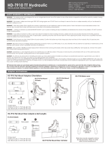 TRP Cycling HD-T910 TT Installation guide
-
Amzer AMZ20609 User manual
-
-
-
BENDIX TCH-020-013 User manual
