Asco Series 448 Rodless Band Cylinders Type STB Owner's manual

Type
Owner's manual
Installation and operation
RODLESS BAND CYLINDERS,
GUIDED CARRIER, WITH PLAIN BEARINGS
Ø 16 to 80 mm
Series 448
Type: STB
NS
1. TECHNICAL DATA
Dimensions, space requirements, weight and other data : See leaflet
P267 on catalogue.
Operating pressure range : pmax = 8 bar.
Speed: > 0,25 m/s or 0,005 m/s (slow speed option).
Compressed air requirements : Free of water and dirt. Additional
lubrication with oil mist is not necessary.
Accessory supplied: Assembly tool.
Noise level : below 70 dB(A).
Installation : In any position.
Temperature Range : From -10° C to 80° C.
The right to introduce technical modifications is reserved.
!
With oil mist lubrication, the cylinder must be supplied with
oil constantly while in operation.
2. TRANSPORT AND INSTALLATION
2.1 Transport
!
Danger from falling load
Inappropriate transport and installation can lead to:
- personal injury
- property damage
Transport of the packed cylinder with a
crane or fork-truck:
Attach the cables or position the forks as
shown.
Transport of the cylinder with a crane:
Attach the cables as shown.
!
The transport company and ASCO-JOUCOMATIC or the
supplying company must be informed of any transport damage
or missing parts in less than 48 hours in writing.
2.2 Interim Storage
Dry and free of dust and vibration. In the open - only on a flat surface
under a cover. Avoid bending!
2.3 Installation
Before installation:
- remove and dispose of all packaging,
- make two strokes of the piston by hand without air pressure.
Carry out the installation in such a way that:
- the regulations in force are observed (e.g. DIN EN 983)
- the cylinder is not warped,
- all connections and operating parts are accessible,
- the labels are readable.
Sources of danger which arise between ASCO-JOUCOMATIC and
the customer’s equipment should be made safe by the user.
!
No welding work should be done after the installation of the
cylinder - the sealing system could be damaged. Remove the
cylinder first or isolate it electrically.
3. COMMISSIONING
!
Check before commissioning:
- the correct connection arrangements, and
- that there is nothing in the way of the moving load.
Commissioning of a Complete Plant
- Make two strokes of piston by hand without air pressure,
- move piston to middle position,
- fully screw in both valve needles for end cushioning,
- unscrew both valve needles about half a turn,
- pressurize plant slowly in order to avoid uncontrolled, dangerous
movements (ASCO-JOUCOMATIC soft-start device).
- adjust speed with throttle non-return valve,
- adjust end cushioning with valve needles.
Commissioning of an Individual Cylinder
- Make two strokes of piston by hand without air pressure,
- move piston to middle position
- fully screw in both valve needles for end cushioning,
- unscrew both valve needles about one turn,
- pressurize both sides equally, piston stops after slight movement,
- vent one side, piston travels to end position,
- start test run,
- adjust speed with throttle non-return valve,
- adjust end cushioning with valve needle.
Re-commissioning after long periods without operation
- Make two strokes of piston by hand without air pressure,
- move piston to middle position,
- continue as for individual cylinder (above).
6. OPERATION
Cleaning: Use only soft rags or other gentle cleaning media.
Problems solving : see table
7. MAINTENANCE
Danger of crushing
!
Carry out maintenance work only with the machine switched
off and the compressed airsystem depressurized.
Observe the operating instructions of the complete plant.
From 6000 Dismantle cylinder completely if necessary, clean parts
and replace worn parts.
When necessary Clean inner sealing band.
See Spare Parts leaflet PR-P267-1.
GB
7
Possible Cause Remedy
Cylinder leaks somewhere
along innersealing band
Cylinder leaks
in piston area
Cylinder leaks
in end cap area
Piston moves slowly
or jerkily
Piston does not reach
end position
Piston impacts too hard
at one or both end positions
Sensors do not work properly
Inner sealing band dirty
Piston seal defective
O-ring seal defective
1) Contamination by air or abrasion.
2) Poor lubrication.
3) Defective piston seal.
4) Speed set too slow.
5) Operating pressure too low.
6) Standard grease in the cylinder.
Cushion needle screwed down too tight.
1) Wrong setting of end cushioning
2) Possibly overload
3) Cushioning needle, O-rings on end caps/cushining
spigot, piston seal or inner sealing band defective.
1) Ferritic parts too close to sensors
2) Sensors defective.
Clean inner sealing band
Replace piston seal
Replace O-ring seal
1-3) Dismantle cylinder completely,
clean and regrease.
Replace wear parts.
4) Increase speed.
5) Check operating pressure.
6) Use slow speed grease.
Adjust cushion needle.
1) Reset with valve needle.
2) Provide additional shock absorber.
3) Check parts and replace if necessary.
1) Use parts made of non-magnetic
material
2) Replace Sensors.
Problems solving
8
Installation and operation
GB
Problem
For fitting and removal of the guide system the complete cylinder
unit should be removed from the machine or plant.
Dismantling of the Guide Carriage
1. Depressurize the cylinder and switch off all electrical power supply.
2. Remove all parts mounted externally on the guide carriage (11).
3. Unscrew one drive block (16) from piston of cylinder, so that the
guide carriage can be moved.
4. For diameters 40 to 80 only: unscrew one end cap from the cylinder.
5. Loosen screws (6) on wiper cover (17).
6. Slide the complete guide carriage off the guide rail.
7. Unscrew wiper cover (7) (or 17+18 for diameters 63 and 80) from
both ends of the guide carriage (11).
8. Inspect the parts – replace damaged or worn parts such as: wiper
(9), slide profile (10) and felt (8) (service kit).
Dismantling and Reassembly of the Guide Rail
1. To dismantle the guide rail (1) remove the screws (4) with their
washers (3). Remove the guide rail (1) and clamping rail (2) from
the cylinder profile.
2. Clean all the parts.
3. Centre the guide rail on the cylinder profile.
4. Fit the clamping rail (2) to the guide rail (1) and screw in the screws
(4) with their washers (3) (use the specified torque).
Reassembly of the Guide Carriage
1. Clean all the parts.
2. Grease the felts (8) with guide grease.
3. Lay the wipers (9) or (21+22) and felts (8) in the wiper covers. The
sealing lip of the wiper must be outwards (see drawing).
4. Back off the adjusting screws (14) in the guide carriage.
5. Lay in the support strip (5) on the same side as the adjusting
screws.
6. Place 2 slide profiles (10) per side in the guide carriage.
The edges of the slide profiles in which grooves are cut (to allow
grease from the grease nipples to get to the guide rail) must touch
each other.
7. Screw on the two wiper covers (7) or (17+18) loosely with the
screws (6).
Remounting the Reassembled Guide Carriage on the Guide Rail
1. Push the complete guide carriage assembly carefully onto the guide
rail with the side with the adjusting screws towards the piston.
2. If necessary move the felt wiper carefully into its correct position
with a screwdriver.
Adjustment of Play and Final Assembly
1. Tighten the self-locking adjusting screws (14), individually from
the middle working outwards, with the specified torque. If non-self-
locking screws are used (14), use a locking medium (Loctite low-
strength is recommended) and tighten the screws from the middle
working outwards until the guide carriage can no longer be moved
by hand.
2. Tap the sides of the guide carriage (11) gently with a rubber hammer
until the slide profiles (10) have settled into position and then tighten
all the adjusting screws (14) again (see above).
3. Loosen all the adjusting screws (14) about 1/4 to 1/2 turn
individually from the middle working outwards.
When correctly adjusted the guide carriage should be easily
movable by hand but with no play.
4. Tighten the screws (6) in the wiper cover (7) or (17+18) with the
specified torque.
5. Position the guide carriage centrally over the cylinder piston and
secure the drive blocks (16) with the washers (13) and screws
(15).
Note: The drive blocks (16) must be fitted against the guide
carriage with no play (11) !!! Note the high torque required !!!
6. Refit the end cap of the cylinder if applicable.
Lubrication
All unused threaded holes in the guide carriage (11) must be plugged
with set screws (12) to prevent escape of lubricant. The grease nipples
on both sides of the guide carriage (11) should be filled with guide
grease until a thin film of grease can be seen on the guide rail when
the guide carriage is moved by hand.
Ø 16 to 50 mm
Ø 63 to 80 mm
Torques for Screws
Item Ø16 Ø25 Ø32 Ø40 Ø50 Ø63 Ø80
4 3 Nm 3 Nm 3 Nm 10 Nm 10 Nm 10 Nm 10 Nm
6 3 Nm 5.5 Nm 5.5 Nm 5.5 Nm 5.5 Nm 5.5 Nm 5.5 Nm
14 1.2 Nm 3.5-4 Nm 3.5-4 Nm 3.5-4 Nm 3.5-4 Nm 3.5-4 Nm 3.5-4 Nm (only self-locking screws)
15 4.5 Nm 9 Nm 14.5 Nm 14.5 Nm 14.5 Nm 35 Nm 40 Nm
19 - - - - - 20 Nm 20 Nm
OPERATING INSTRUCTIONS FOR STB CYLINDER
9
GB
For fitting and removal of the guide system the complete cylinder
unit should be removed from the machine or plant.
Dismantling of the Guide Carriage
1. Depressurize the cylinder and brake lines and switch off all
electrical power supply.
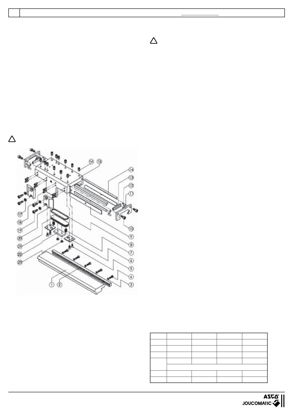
2. Remove all parts mounted externally on the guide carriage (15).
3. Unscrew drive block (20) from piston of cylinder, so that the guide
carriage can be moved.
4. For the diameters 40 and 50 only: unscrew one end cap of the
cylinder.
5. Loosen the screws (10) on the wiper cover (11).
6. Slide the complete guide carriage off the guide rail.
7. Unscrew the wiper cover (11) from both ends of the guide
carriage (15).
8. Inspect the parts – replace damaged or worn parts such as:
wiper (13), slide profile (14) and felt (12) (service kit).
Dismantling of the Brake
1. Remove screws (5) and remove the plates (6) and springs (7) from
the guide carriage.
2. To remove the brake piston (21), apply compressed air to its air
connection and blow it out (do not use sharp tools on the piston!).
!
Hold the brake piston while blowing it out!
3. Remove screws (23) and remove the brake lining (22) from the
brake piston (21) and the O-ring (8).
4. Inspect the parts – replace damaged or worn parts such as: O-
ring (8) and brake lining (22).
Dismantling and Reassembly of the Guide Rail
1. Remove the screws (4) with their washers (3). Remove the guide
rail (1) and clamping rail (2) from the cylinder profile.
2. Clean all the parts.
3. Centre the guide rail on the cylinder profile.
4. Secure the guide rail (1) and clamping rail (2) with the screws (4)
and their washers (3) (use the specified torque).
Reassembly of the Brake
1. Clean all the parts, the inside of the brake piston chamber and the
brake air connection.
2. Fit the brake lining (22) to the brake piston (21). Apply a locking
medium (Loctite low-strength is recommended) to the screws (23)
and tighten them.
3. Grease the walls of the brake piston chamber and the groove in
the brake piston lightly with guide grease.
!
The brake lining must be grease-free.
4. Locate the O-ring (8) in the brake piston (21) and grease the O-
ring lightly.
5. Fit the brake piston (21) into the guide carriage (15).
6. Fit the springs (7) and plates (6). Apply a locking medium to the
screws (5) and tighten them.
Reassembly of the Guide Carriage
1. Clean all the parts.
2. Grease the felts (12) with guide grease.
3. Lay the wipers (13) and felts (12) in the wiper covers.
The sealing lip of the wiper must be outwards (see drawing).
4. Back off the adjusting screws (18) in the guide carriage.
5. Lay in the support strip (9) on the same side as the adjusting
screws.
6. Place 2 slide profiles (14) per side in the guide carriage.
The edges of the slide profiles in which grooves are cut (to allow
grease from the grease nipples to get to the guide rail) must touch
each other.
7. Screw on the two wiper covers (11) loosely with the screws (10).
Remounting the Reassembled Guide Carriage on the Guide Rail
1. Push the complete guide carriage assembly carefully onto the guide
rail with the side with the adjusting screws towards the piston.
2. If necessary move the felt wiper carefully into its correct position
with a screwdriver.
Adjustment of Play
1. Tighten the self-locking adjusting screws (18), individually from
the middle working outwards, with the specified torque. If non-self-
locking screws are used (18), use a screw locking system (Loctite
low-strength is recommended) and tighten the screws from the
middle working outwards until the guide carriage can no longer be
moved by hand.
2. Tap the sides of the guide carriage (15) gently with a rubber hammer
until the slide profiles (14) have settled into position and then tighten
all the adjusting screws (18) again (see above).
3. Loosen all the adjusting screws (18) about 1/4 to 1/2 turn
individually from the middle working outwards.
When correctly adjusted the guide carriage should be easily
movable by hand but with no play.
4. Tighten the screws (10) in the wiper cover (11) with the prescribed
torque.
Lubrication
1. All unused threaded holes in the guide carriage (15) must be
plugged with set screws (16) to prevent escape of lubricant. The
grease nipples on both sides of the guide carriage (15) should be
filled with guide grease until a thin film of grease can be seen on
the guide rail when the guide carriage is moved by hand.
Final Assembly
1. Position the guide carriage centrally over the cylinder piston and
secure the drive blocks (20) with the washers (17) and screws
(19).
Note: The drive blocks (20) must be fitted against the guide
carriage with no play (15) !!! See the table for the correct
torque !!!
2. Refit the end cap of the cylinder, if applicable.
OPERATING INSTRUCTIONS FOR STB CYLINDER WITH ACTIVE BRAKE (Ø25 to 50 mm)
10
Torques for Screws
Item Ø25 Ø32 Ø40 Ø50
4 3 Nm 3 Nm 10 Nm 10 Nm
5 3 Nm 3 Nm 3 Nm 3 Nm
10 5.5 Nm 5.5 Nm 5.5 Nm 5.5 Nm
18
3.5-4 Nm 3.5-4 Nm 3.5-4 Nm 3.5-4 Nm
19 9 Nm 14.5 Nm 14.5 Nm 14.5 Nm
23 0.8-1 Nm 0.8-1 Nm 0.8-1 Nm 0.8-1 Nm
(only self-locking screws)
GB
For fitting and removal of the guide system the complete cylinder
unit should be removed from the machine or plant.
Dismantling of the Guide Carriage
1. Depressurize the cylinder and brake lines and switch off all
electrical power supply.
2. Remove all parts mounted externally on the plate (22).
3. Unscrew the screws (21) with their washers (20), backing off each
screw a little at a time, so that the plate (22) does not tip and jam
when it is removed from the guide carriage (23).
4. Remove the plate (22) from the guide carriage (23).
5. Unscrew one drive block (27) from the piston of the cylinder so
that the guide carriage can be moved.
6. Loosen the screws (7) in the wiper cover (8 or 28 + 29).
7. For the diameters 40 to 80 only: remove one end cap of the cylinder.
8. Slide the complete guide carriage (23) off the guide rail (1).
9. Unscrew the wiper covers (8 or 28 + 29) from both ends of the
guide carriage (23).
10. Inspect the parts – replace damaged or worn parts such as: wiper
(10 or 30 + 31), slide profile (11) and felt (9) (service kit).
Dismantling of the Brake
1. Remove the saucer springs (18) and pressure plates (19) and press
the brake piston (15) out of the guide carriage (23) from the brake
lining side.
2. Remove the screws (12) and remove the brake lining (13) and
guide pin (17) from the brake piston (15), and also the O-rings
(14) and (16).
3. Inspect the parts – replace damaged or worn parts such as: O-
rings (14) and (16) and brake lining (13).
Dismantling and Reassembly of the Guide Rail
1. Unscrew the screws (4) with their washers (3).
Remove the guide rail (1) and clamping rail (2) from the cylinder
profile.
2. Clean all the parts.
3. Centre the guide rail (1) on the cylinder profile. Secure the guide
rail (1) and clamping rail (2) with the screws (4) and their washers
(3) (use the specified torque).
Reassembly of the Brake
1. Clean all the parts, the inside of the brake piston chamber and the
brake air connection.
2. Centre the guide pin (17) on the brake piston with the help of the
pressure plate (19) and fit the brake lining (13) on the brake piston
(15), applying a locking medium (Loctite low-strength is
recommended) to the screw (12) and tightening it.
3. Grease the walls of the brake piston chamber and the groove in
the brake piston lightly with guide grease.
!
The brake lining must be grease-free.
4. Locate the O-rings (14) and (16) in the brake piston (15) and grease
the O-rings lightly.
5. Fit the brake piston (15) into the guide carriage (23).
Ø 25 to 50 mm
Ø 63 to 80 mm
OPERATING INSTRUCTIONS FOR CYLINDER STB WITH
PASSIVE BRAKE (Ø25 to 80 mm)
11
GB
Reassembly of the Guide Carriage
1. Clean all the parts.
2. Grease the felts (9) with guide grease.
3. Lay the wipers (10 or 30 + 31) and felts (9) in the wiper covers.
The sealing lip of the wiper must be outwards (see drawing).
4. Back off the adjusting screws (24) in the guide carriage.
5. Lay in the support strip (6) on the same side as the adjusting
screws.
6. Place 2 slide profiles (11) per side in the guide carriage.
The edges of the slide profiles in which grooves are cut (to allow
grease from the grease nipples to get to the guide rail) must touch
each other.
7. Screw on the two wiper covers (8 or 28 + 29) loosely with the
screws (7).
Remounting the Reassembled Guide Carriage on the Guide Rail
1. Push the complete guide carriage assembly carefully onto the guide
rail with the side with the adjusting screws towards the piston.
2. If necessary move the felt wiper carefully into its correct position
with a screwdriver.
Adjustment of Play
1. Tighten the self-locking adjusting screws (24), individually from
the middle working outwards, with the specified torque. If non-self-
locking screws are used (24), use a locking medium (Loctite low-
strength is recommended) and tighten the screws from the middle
working outwards until the guide carriage can no longer be moved
by hand.
2. Tap the sides of the guide carriage (23) gently with a rubber hammer
until the slide profiles (11) have settled into position and then tighten
all the adjusting screws (24) again (see above).
3. Loosen all the adjusting screws (24) about 1/4 to 1/2 turn
individually from the middle working outwards. When correctly
adjusted the guide carriage should be easily movable by hand but
with no play.
4. Tighten the screws (7) in the wiper cover (8 or 28 + 29) with the
prescribed torque.
Lubrication
The grease nipples on both sides of the guide carriage (23) should
be filled with guide grease until a thin film of grease can be seen on
the guide rail when the guide carriage is moved by hand.
Final assembly
1. Position the guide carriage centrally over the cylinder piston and
secure the drive blocks (27) with the washers (26) and screws
(25).
Note: The drive blocks (27) must be fitted against the guide
carriage (23) or carrier (34) with no play !!! See the table for the
correct torque !!!
2. Push the saucer springs (18) and pressure plates (19) onto the
guide pin.
Note: See the diagram for the correct arrangement of the saucer
springs and pressure plates. Depending on the brake type the
numbers of saucer springs (18) and pressure plates (19) are different.
3. Lay the plate (22) on the
pressure plates (19).
4. Tighten the screws (21) with
their washers (20) gradually
and evenly until the plate (22)
lies completely flat on the
guide carriage (23).
5. Refit the end cap of the
cylinder, if applicable.
Torques for screws
Item Ø25 Ø32 Ø40 Ø50 Ø63 Ø80
4 3 Nm 3 Nm 10 Nm 10 Nm 10 Nm 10 Nm
7 5.5 Nm 5.5 Nm 5.5 Nm 5.5 Nm 5.5 Nm 5.5 Nm
12 0.8-1 Nm 0.8-1 Nm 0.8-1 Nm 0.8-1 Nm 0.8-1 Nm 0.8-1 Nm
21 5.5 Nm 10 Nm 10 Nm 10 Nm 20 Nm 20 Nm
24
3.5-4 Nm 3.5-4 Nm 3.5-4 Nm 3.5-4 Nm 3.5-4 Nm 3.5-4 Nm
25 9 Nm 14.5 Nm 14.5 Nm 14.5 Nm 35 Nm 35 Nm
32 - - - - 20 Nm 20 Nm
(only self-locking screws)
OPERATING INSTRUCTIONS FOR CYLINDER STB WITH PASSIVE BRAKE (Ø25 to 80 mm)
12
GB
  • Page 1 1
  • Page 2 2
  • Page 3 3
  • Page 4 4
  • Page 5 5
  • Page 6 6
  • Page 7 7
  • Page 8 8
  • Page 9 9
  • Page 10 10
  • Page 11 11
  • Page 12 12
  • Page 13 13
  • Page 14 14
  • Page 15 15
  • Page 16 16
  • Page 17 17
  • Page 18 18
  • Page 19 19
  • Page 20 20
  • Page 21 21
  • Page 22 22
  • Page 23 23
  • Page 24 24
  • Page 25 25
  • Page 26 26
  • Page 27 27
  • Page 28 28
  • Page 29 29
  • Page 30 30
  • Page 31 31
  • Page 32 32
  • Page 33 33
  • Page 34 34
  • Page 35 35
  • Page 36 36
  • Page 37 37
  • Page 38 38

Asco Series 448 Rodless Band Cylinders Type STB Owner's manual

Type
Owner's manual

Ask a question and I''ll find the answer in the document

Finding information in a document is now easier with AI