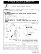
Page is loading ...

24” and 36” Dual Fuel Free-Standing Range
Cuisinière autoportante à bi-combustible de
24” et 36”
Estufa independiente para dos combustibles
de 24” y 36”
Installation Instructions
Instructions d’installation
Instrucciones de instalación
HCR2250ADS
HCR6250ADS
F
o


1
TABLE OF CONTENTS
RANGE SAFETY ...................................................................................................1
INSTALLATION REQUIREMENTS ......................................................................... 3
Location Requirements ................................................................................................. 3
Given Dimensions are Minimum Clearances. ............................................................... 4
Electrical Requirements - Canada Only ........................................................................ 6
Gas Supply Requirements .............................................................................................7
INSTALL RANGE ................................................................................................ 10
Install Anti-Tip Bracket ................................................................................................10
Electrical Connection ..................................................................................................10
Gas Connection ...........................................................................................................14
Converting to Dierent Types Of Gas ........................................................................ 15
Abnormal Operation ....................................................................................................17
RANGE SAFETY
Your safety and the safety of others are very important.
We have provided many important safety messages in this manual and
on your appliance. Always read and obey all safety messages.
DANGER
WARNING
CAUTION
This is the safety alert symbol.
This symbol alerts you to potential hazards that can
kill or hurt you and others. All safety messages will
follow the safety alert symbol and either the word
“DANGER,” “WARNING” or “CAUTION.”
These words mean:
An imminently hazardous situation. You
could be killed or seriously injured if you
don’t immediately follow instructions.
A potentially hazardous situation
which, if not avoided, could result in
death or serious bodily injury.
A potentially hazardous situation
which, if not avoided, may result in
moderate or minor injury.
All safety messages will tell you what the potential hazard is, tell you
how to reduce the chance of injury, and tell you what can happen if the
instructions are not followed.

2
WARNING
Fire Hazard
If the information in this manual is not followed exactly, a fire or
explosion may result causing property damage, personal injury or
death.
- Do not store or use gasoline or other flammable vapors and liquids in
the vicinity of this or any other appliance.
- WHAT TO DO IF YOU SMELL GAS
• Do not try to light any appliance.
• Do not touch any electrical switch.
• Do not use any phone in your building.
• Immediately call your gas supplier from a neighbor’s phone. Follow
the gas supplier’s instructions.
• If you cannot reach your gas supplier, call the fire department.
- Installation and service must be performed by a qualified installer,
service agency or the gas supplier.
In the State of Massachusetts, the following installation instructions
apply:
•
Installations and repairs must be performed by a qualied or
licensed contractor, plumber, or gastter qualied or licensed by the
State of Massachusetts.
•
If using a ball valve, it shall be a T-handle type.
•
A exible gas connector, when used, must not exceed 3 feet.

3
WARNING
Tip Over Hazard
A child or adult can tip the range and be killed.
Connect anti-tip bracket to rear range foot.
Reconnect the anti-tip bracket, if the range is moved.
Failure to follow these instructions can result in death or serious burns
to children and adults.
INSTALLATION REQUIREMENTS
LOCATION REQUIREMENTS
IMPORTANT: Observe all governing codes and ordinances. Do not obstruct ow of
combustion and ventilation air.
•
It is the installer’s responsibility to comply with installation clearances specied
on the model/serial rating plate. The model/serial rating plate is located inside
the oven door on the right-hand side oven door trim.
•
The range should be located for convenient use in the kitchen.
•
Recessed installations must provide complete enclosure of the sides and rear of
the range.
•
To eliminate the risk of burns or re by reaching over heated surface units,
cabinet storage space located above the surface units should be avoided. If
cabinet storage is to be provided, the risk can be reduced by installing a range
hood or microwave hood combination that projects horizontally a minimum of 5”
(12.7 cm) beyond the bottom of the cabinets.
•
All openings in the wall or oor where range is to be installed must be sealed.
•
Do not seal the range to the side cabinets.
•
Cabinet opening dimensions that are shown must be used.
•
Grounded electrical supply is required. See “Electrical Requirements” section.
•
Proper gas supply connection must be available. See “Gas Supply Requirements”
section.
•
Contact a qualied oor covering installer to check that the oor covering can
withstand at least 200°F (93°C).
•
Use an insulated pad or ” (0.64 cm) plywood under range if installing range over
carpeting.

4
IMPORTANT: Some cabinet and building materials are not designed to withstand
the heat produced by the oven for baking and self-cleaning. Check with your builder
or cabinet supplier to make sure that the materials used will not discolor, delaminate
or sustain other damage.
GIVEN DIMENSIONS ARE MINIMUM CLEARANCES.
PRODUCT DIMENSIONS
ELECTRICAL REQUIREMENTS - U.S.A. ONLY
If codes permit and a separate ground wire is used, it is recommended that a
qualied electrical installer determine that the ground path is adequate and wire
gauge is in accordance with local codes.
Do not use an extension cord.
Be sure that the electrical connection and wire size are adequate and in
conformance with the National Electrical Code, ANSI/ NFPA No. 7-latest edition and
all local codes and ordinances.
A copy of the above code standards can be obtained from:
National Fire Protection Association
One Batterymarch Park
Quincy, MA 02269

5
WARNING
Electrical Shock Hazard
The electrical power to the oven branch circuit must be shut off while
line connections are being made.
Do not use an extension cord with this appliance.
Electrical ground is required on this appliance. The free end of the green
wire (the ground wire) must be connected to a suitable ground. This
wire must remain grounded to the oven.
If cold water pipe is interrupted by plastic, non metallic gaskets, union
connections or other insulating materials, DO NOT use for grounding.
DO NOT ground to a gas pipe.
DO NOT have a fuse in the NEUTRAL or GROUNDING circuit. A fuse in
the NEUTRAL or GROUNDING circuit could result in an electrical shock.
Check with a qualified electrician if you are in doubt as to whether the
appliance is properly grounded.
Failure to do so could result in death or serious injury.
Use a 3-wire, UL listed, 40-amp power supply cord (pigtail); or if local codes do
not permit ground through the neutral, use a 4-wire power supply cord rated at
250volts, 40 amps and investigated for use with ranges.
Electrical Connection
To properly install your range, you must determine the type of electrical connection
you will be using and follow the instructions provided for it here.
•
Range must be connected to the proper electrical voltage and frequency as
specied on the model/serial number rating plate. All models are dual rated, and
designed to be connected to either 208/240V AC, 60Hz, 3-wire or 4-wire, two-
phase power supply.
Circuit Required
•
208V, 60Hz
•
240V, 60Hz
•
12AMP
•
15AMP
•
The electrical supply should be a 3-wire or 4-wire, two-phase AC. Install a
suitable conduit box (not furnished). An appropriately sized, U-listed conduit
connector must be used to correctly attach the conduit to the junction box.
IMPORTANT: Local Codes may vary; installation electrical connections and
grounding must comply with all applicable local codes.
If local codes permit grounding through the electrical supply neutral, connect both
the white neutral wire and the green ground wire from the oven to the white neutral
electrical supply wire.

6
ELECTRICAL REQUIREMENTS - CANADA ONLY
WARNING
Electrical Shock Hazard
Electrically ground range.
Failure to do so can result in death, fire or electrical shock.
If codes permit and a separate ground wire is used, it is recommended that a
qualied electrical installer determine that the ground path is adequate and wire
gauge are in accordance with local codes.
Be sure that the electrical connection and wire size are adequate and in
conformance with CSA Standard C22.1, Canadian Electrical Code, Part 1 - latest
edition, and all local codes and ordinances.
A copy of the above code standards can be obtained from:
Canadian Standards Association
178 Rexdale Blvd.
Toronto, ON M9W 1R3 CANADA.
•
Check with a qualied electrical installer if you are not sure the range is properly
grounded.
•
When a 4-wire, single phase 120/240 volt, 60 Hz., AC only electrical supply is
available, a 50-amp maximum circuit protection is required (or, if specied on
the model/serial rating plate, when a 4-wire, single phase 120/208 volt 60 Hz.,
AC only electrical supply is available, a 40-amp maximum circuit protection is
required), fused on both sides of the line.
•
A time-delay fuse or circuit breaker is recommended.
•
This range is equipped with a CSA International Certied Power Cord intended
to be plugged into a standard 14-50R wall receptacle. Be sure the wall receptacle
is within reach of range’s nal location.
•
Do not use an extension cord.

7
GAS SUPPLY REQUIREMENTS
WARNING
Explosion Hazard
Use a new CSA International approved gas supply line.
Install a shut-off valve.
Securely tighten all gas connections.
If connected to LP, have a qualified person make sure gas pressure
does not exceed 14" (36 cm) water column.
Examples of a qualified person include:
licensed heating personnel,
authorized gas company personnel, and
authorized service personnel.
Failure to do so can result in death, explosion or fire.
Observe all governing codes and ordinances.
IMPORTANT: This installation must conform with all local codes and ordinances.
In the absence of local codes, installation must conform with American National
Standard, National Fuel Gas Code ANSI Z223.1 - latest edition or CAN/CGA B149 –
latest edition.
IMPORTANT: Leak testing of the range must be conducted according to the
manufacturers instructions.
TYPE OF GAS
Natural gas:
This range is design-certied by CSA International for use with Natural gas or, after
proper conversion, for use with LP gas.
•
This range is factory set for use with Natural gas. See “Gas Conversions”
section. The model/serial rating plate located on the right side oven door trim
has information on the types of gas that can be used. If the types of gas listed do
not include the type of gas available, check with the local gas supplier.
LP gas conversion:
Conversion must be done by a qualied service technician.
No attempt shall be made to convert the appliance from the gas specied on the
model/serial rating plate for use with a dierent gas without consulting the serving
gas supplier. See “Gas Conversions” section.

8
GAS SUPPLY LINE
Provide a gas supply line of ” (1.9 cm) rigid pipe to the range location. A smaller
size pipe on longer runs may result in insucient gas supply. Pipe-joint compounds
that resist the action of LP gas must be used. With LP gas, piping or tubing size can
be ” (1.3 cm) minimum. Usually, LP gas suppliers determine the size and materials
used in the system.
Flexible metal appliance connector:
•
If local codes permit, a new CSA design-certied, 4 - 5 ft (122 - 152.4 cm) long,
” (1.3 cm) or 3/4” (1.9 cm) I.D., exible metal appliance connector may be used
for connecting range to the gas supply line.
•
GRAPHIC – APPLIANCE CONNECTOR
•
A ” (1.3 cm) male pipe thread is needed for connection to the female pipe
threads of the inlet to the appliance pressure regulator.
•
Do not kink or damage the exible metal tubing when moving the range.
Rigid pipe connection:
The rigid pipe connection requires a combination of pipe ttings to obtain an in-line
connection to the range. The rigid pipe must be level with the range connection. All
strains must be removed from the supply and fuel lines so range will be level and in
line.
•
Must include a shuto valve:
•
The supply line must be equipped with a manual shuto valve. This valve should
be located in the same room but external to the range. It should be in a location
that allows ease of opening and closing. Do not block access to shuto valve.
The valve is for turning on or shutting o gas to the range.
a b c
a Gas Supply Line
b Shuto Valve “Open” Position
c To Range

9
GAS PRESSURE REGULATOR
The gas pressure regulator supplied with this range must be used. The inlet pressure
to the regulator should be as follows for proper operation:
Natural gas:
Minimum pressure: 5” WCP
Maximum pressure: 14” WCP
LP gas:
Minimum pressure: 11” WCP
Maximum pressure: 14” WCP
Contact local gas supplier if you are not sure about the inlet pressure.
Burner Input Requirements
Input ratings shown on the model/serial rating plate are for elevations up to 2,000 ft
(609.6 m).
For elevations above 2,000 ft (609.6 m), ratings are reduced at a rate of 4% for each
1,000 ft (304.8 m) above sea level (not applicable for Canada).
GAS SUPPLY PRESSURE TESTING
Line pressure testing above 0.5 psi gauge (14” WCP)
The range and its individual shuto valve must be disconnected from the gas supply
piping system during any pressure testing of that system at test pressures in excess
of 0.5 psi (3.5 kPa).
Line pressure testing at 0.5 psi gauge (14” WCP) or lower
The range must be isolated from the gas supply piping system by closing its
individual manual shuto valve during any pressure testing of the gas supply piping
system at test pressures equal to or less than 0.5 psi (3.5 kPa).

10
INSTALL RANGE
INSTALL ANTI-TIP BRACKET
IMPORTANT:
•
An Anti-Tip Bracket kit is included with the range. Follow the instructions
supplied with the anti-tip bracket.
•
Do not completely remove the rear leveling leg. The anti-tip bracket uses the
rear leveling leg to secure the range to the oor.
•
The anti-tip bracket should be installed, so that it secures either the right or left
rear leveling leg.
•
After installing the leveling leg, note the distance from the side of the range to
the center of the leveling leg. Mark this location on the oor.
•
Attach the anti-tip bracket to the oor with 4 screws so that the rear leveling leg
will be centered within the bracket once it is in its nal position.
NOTE: Contact a qualied oor covering installer for the best procedure for drilling
mounting holes through your type of oor covering.
ELECTRICAL CONNECTION
POWER SUPPLY CORD
WARNING
Electrical Shock Hazard
Disconnect power before servicing.
Use a new 40 amp power supply cord.
Plug into a grounded outlet.
Failure to do so can result in death, fire or electrical shock.
1. Disconnect power.
2. Remove the terminal block cover screws located on the back of the range. Pull
cover down and toward you to remove cover.
3. Add strain relief.

11
Power supply cord strain relief
•
Remove the knockout for the 40-amp supply cord.
•
Assemble a UL listed strain relief in the opening.
•
Feed the power supply cord behind the black horizontal cross brace and through
the strain relief, allowing enough slack to easily attach the wiring to the terminal
block.
•
Tighten strain relief screw against the power supply cord.
DIRECT WIRE
WARNING
Electrical Shock Hazard
Disconnect power before servicing.
Use 8 gauge copper or 6 gauge aluminum wire.
Electrically ground range.
Failure to do so can result in death, fire or electrical shock.
Be sure your appliance is properly installed and grounded by a qualied
technician. Ask your dealer to recommend a qualied technician or an authorized
repair service.
This appliance is manufactured with a green GROUND wire connected to the oven
chassis. After making sure that the power has been turned o, connect the exible
conduit fromthe oven to the junction box using a U.L. listed conduit connector. The
Grounded Neutral and Ungrounded Neutral Graphics on the following pages and the
instructions provided, present the most common way of connecting the ovens. Your
local codes and ordinances, of course, take precedence over these instructions.
Complete electrical connections according to local codes and ordinances

12
3-WIRE CONNECTION
WARNING
Electrical Shock Hazard
Frame grounded to neutral of appliance through a link
Grounding through the neutral conductor is prohibited for new
branch-circuit installations (1996 NEC); mobile homes; and recreational
vehicles, or in an area where local codes prohibit grounding through the
neutral conductor. For installations where grounding through the
neutral conductor is prohibited, see the Ungrounded Neutral graphic.
Disconnect the ground from the neutral at free end of conduit.
Use grounding terminal or lead to ground unit.
Connect neutral terminal or lead to branch circuit neutral in usual
manner.
Failure to do so could result in death, fire or electric shock.
Where local codes allow the connection of GROUND wire from the oven to the
branch circuit NEUTRAL wire (gray or white colored wire):
•
If local codes permit, connect the green GROUND wire from the oven and the
white wire from the oven to the branch circuit NEUTRAL wire (gray or white
colored wire).
•
Connect the red and black leads from the oven to the corresponding leads in the
junction box.

13
Grounded Neutral
a
b
c
d
g
f
e
h
a Junction Box
b Red Wires
c White Wires
d Green Wire
e Cable from Oven
f U.L. Listed Conduit
Connector
g Black Wires
h Cable from Power Supply
4-WIRE CONNECTION
•
Disconnect ground from neutral at free end of conduit.
•
Connect the green GROUND wire from the oven to the GROUND wire in the
junction box (bare or green colored wire).
•
Connect the red and black leads from the oven to the corresponding leads in the
junction box.
•
Connect the white wire from the oven to the NEUTRAL (gray or white) wire in the
junction box.
Ungrounded Neutral
a
b
c
g
f
de
h
a Junction Box
b Red Wires
c Green Wires
d Cable from Oven
e U.L. Listed Conduit
Connector
f Black Wires
g White Wires
h Cable from Power Supply

14
ELECTRICAL FEATURES
Oven Light 25 W
Spit Motor 4 W
Upper Heating Element 1950 W
Bottom Heating Element 1800 W
Grill Heating Element 2250S
Circular Heating Element 1800 W
Ventilator Motor 30 W
Cooling Fan 11 W
This appliance shall be installed only by authorized persons and in accordance with
the manufacturer’s installation instructions, local gas tting regulations, municipal
building codes, electrical wiring regulations, local water supply regulations.
GAS CONNECTION
WARNING
Explosion Hazard
Use a new CSA International approved gas supply line.
Install a shut-off valve.
Securely tighten all gas connections.
If connected to LP, have a qualified person make sure gas pressure
does not exceed 14" (36 cm) water column.
Examples of a qualified person include:
licensed heating personnel,
authorized gas company personnel, and
authorized service personnel.
Failure to do so can result in death, explosion or fire.
TYPICAL RIGID PIPE CONNECTION
A combination of pipe ttings must be used to connect the range to the existing gas
line. Your connections may be dierent, according to the supply line type, size and
location.
1. Apply pipe-joint compound made for use with LP gas to all pipe thread
connections.
2. Using a pipe wrench to tighten, connect the gas supply to the range.

15
TYPICAL FLEXIBLE CONNECTION
1. Apply pipe-joint compound made for use with LP gas to the smaller thread ends
of the exible connector adapters.
2. Attach one adapter to the gas pressure regulator and the other adapter to the
gas shuto valve. Tighten both adapters.
3. Use a 15/16” combination wrench and channel lock pliers to attach the exible
connector to the adapters. Check that connector is not kinked.
COMPLETE CONNECTION
1. Open the manual shuto valve in the gas supply line. The valve is open when the
handle is parallel to the gas pipe.
2. Test all connections by brushing on an approved noncorrosive leak-detection
solution. If bubbles appear, a leak is indicated. Correct any leak found.
3. Plug in range or reconnect power.
CONVERTING TO DIFFERENT TYPES OF GAS
When converting from Universal LPG to Natural Gas ensure that the LPG test point
is removed and replaced with the CE Approved NG Regulator supplied in this kit. The
test point pressure must be adjusted to 4”W.C with the largest burner operating on
maximum ame.
When converting from Natural Gas to Universal LPG ensure that the NG regulator
is removed and replaced with the Test Point Assembly supplied in this kit. An CE
Approved gas regulator suitable for a supply pressure of 10”W.C should be part of
the gas tank supply and the test point pressure must be adjusted to 10”W.C.
To adapt the range to a gas dierent from that for which it was set up (see gas type
label inside the warming compartment door) proceed as follows:
1. Remove the grids
2. Remove the burners caps and burner heads
3. Using a 7 mm socket spanner unscrew and remove the injectors.

16
4. Replace the injectors with those supplied corresponding to the gas available (see
Burner and Injector Characteristics table).
5. Replace the various parts proceeding in reverse.
When converting from Natural Gas to LPG ensure that the NG regulator is removed
and replaced with the Test Point Assembly. A gas regulator suitable for a supply
pressure of should be part of the gas tank supply and the test point pressure should
be adjusted to the pressure according to the data plate.
SETTING THE MINIMUM FLAME
The ame on the small output is regulated by the factory. When the injectors have
been replaced or there are special mains pressure conditions, it may be necessary to
regulate the minimum ame again.
To set the minimum ame:
•
Light the burner
•
Turn the knob to the minimum position
•
Take out the knob (and gasket if there is one). Turn the screw fully clockwise, and
then turn it counterclockwise turn for the Triple ring and 1/8 turn for all other
burners. The result should be a small, stable ame uniform around the entire
burner ring. If not, turn the by-pass screw counterclockwise until satised with
the ame.
•
Put the knob back on and turn it quickly from the maximum position to the
minimum position, checking that the ame does not go out.
•
For burners with safety valve, make sure that the regulation obtained is
sucient to maintain heating of the thermocouple. If it is not, increase the
minimum.
THE BURNERS REQUIRE NO REGULATION OF THE PRIMARY AIR.

17
ABNORMAL OPERATION
ANY OF THE FOLLOWING ARE CONSIDERED TO BE ABNORMAL OPERATION
AND MAY REQUIRE SERVICING:
•
Yellow tipping of the hob burner ame.
•
Sooting up of cooking utensils.
•
Burners not igniting properly.
•
Burners failing to remain lit.
•
Burners extinguished by oven door.
•
Gas valves, which are dicult to turn.
IN CASE THE APPLIANCE FAILS TO OPERATE CORRECTLY, CONTACT THE
AUTHORIZED SERVICE PROVIDER IN YOUR AREA
Burner and Injector Characteristic Table
Burner Position
Injector Gas Pressure Rate
Diam. (mm) Type [i.w.c.] [BTU/h]
Auxiliary Front R 1.1 NG 4” 4967
0.7 LP (Propane) 10” 4879
Semi-Rapid Rear L and R 1.29 NG 4” 7055
0.8 LP (Propane) 10” 6472
Dual Burner Center Inner 0.99*5 NG 4” 17882
Center Outer 0.56*6 LP (Propane) 10” 15586
2
2
3
1
22
4
3
a a
a Opening in grate for wok ring (provided) is located over left front burner.

IMPORTANT
Do Not Return This Product To The Store
If you have a problem with this product, please contact the
“Haier Customer Satisfaction Center” at
1-877-337-3639.
DATED PROOF OF PURCHASE, MODEL #, AND SERIAL #
REQUIRED FOR WARRANTY SERVICE
IMPORTANT
Ne pas Réexpédier ce Produit au Magasin
Pour tout problème concernant ce produit, veuillez contacter
le service des consommateurs “Haier Customer Satisfaction Center” au
1-877-337-3639.
UNE PREUVE D’ACHAT DATEE EST REQUISE POUR BENEFICIER DE LA GARANTIE.
IMPORTANTE
No regrese este producto a la tienda
Si tiene algún problema con este producto, por favor contacte el
“Centro de Servicio al Consumidor de Haier” al
1-877-337-3639 (Válido solo en E.U.A).
NECESITA UNA PRUEBA DE DE COMPRA FECHADA, NÚMERO DE MODELO
Y DE SERIE PARA EL SERVICIO DE LA GARANTÍA
Made in China
Fabriqué en Chine
Hecho en China
Haier America
Wayne, NJ 07470
HCR2250ADS
HCR6250ADS
Issued: March 2015 Printed in China Part # 00XXXXXXXXX
/