Page is loading ...

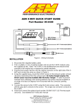
FIGURE 1. WIRING DIAGRAM
AEM Performance Electronics
2205 126
th
Street Unit A, Hawthorne, CA. 90250
Phone: (310) 484-2322 Fax: (310) 484-0152
http://www.aemelectronics.com
Instruction Part Number: 10-2340-N
© 2012 AEM Performance Electronics
Part Number 30-2340-N
AEM 4-CH WIDEBAND UEGO CONTROLLER WITH
NASCAR SPEC ECU CAN CONFIGURATION

Page 2
INSTALLATION
PROCEDURE OVERVIEW
1. Disconnect the negative battery cable.
2. Find a suitable mounting location for the 4 CH UEGO controller, away from any
direct heat or water sources and shielded from the elements.
3. Connect the flying lead analog output wires as shown in Figure 1.
4. Mount the UEGO sensors as shown in figure 2.
5. Plug the UEGO sensor connector on the harness into the mating connector on
each UEGO sensor.
6. Install the 30-2064 EBP sensor kit* and connect it as shown in Figure 1.
* Sold Separately
WIRING INSTRUCTIONS
Power
RED - Connect to a switched, fused (20A) 12-volt power source, that is on only when
the engine is running.
BLACK – Connect to a clean power ground.
Outputs
WHITE - Connect to Lambda + Input.
BLACK - Connect to sensor ground. Connect to power ground if sensor ground is not
available.
AEM 4 CH UEGO Controller Parts
1 x 35-2340 4 CH UEGO Module
1 x 35-2908 Wiring Harness
4 x 1-2059 6-32 Stainless Steel Hex Nut
4 x 1-2047 6-32 x 1 ¼ screw
1 x 10-2340-N Installation Instructions

Page 3
MOUNTING INSTRUCTIONS
UEGO Sensor Mounting
A high flow stainless steel weld-in sensor bung is needed for sensor installation
(additional sensors & bungs are available 30-2063). The bung is specifically designed
so the sensor can provide accurate AFR readings with minimal flow intrusion and
survive extreme exhaust gas temperatures. Pick a mounting location(s) that allows for
easy access to the sensor(s). The sensor tip must be exposed to exhaust gas in order
to give accurate AFR readings. For thin wall tubing, drill a 15/16” hole and weld in the
bung. For thick wall tubing/ castings, drill a 1 1/16” hole and weld in the bung. The
sensor must be mounted at an angle of at least 10 degrees from horizontal in order to
prevent liquids from collecting in the sensor housing. See Figure 2 below. NOTE:
THE OPTIONAL AEM EBP (EXHAUST BACK PRESSURE) KIT (PART # 30-2064)
MUST BE USED IF SENSORS ARE MOUNTED PRE-TURBO.
Controller Mounting
Mount the controller using the supplied 6-32 x 1 ¼ stainless steel screws and nuts. See
Figure 3 and Figure 4 for mounting holes and footprint size.
FIGURE 2. Sensor Bung and Sensor Mounting

Page 4
FIGURE 3. Mounting holes
FIGURE 4. Dimensions
OPERATING INSTRUCTIONS
INDICATOR LIGHTS
The AEM 4 CH UEGO controller has eight indicator LEDs, one Status and one Ready
LED for each channel (Figure 5). Both Ready and Status LEDs flash during sensor
Mounting
Screws

Page 5
warm up. Once the UEGO sensor reaches operating temperature, usually within 30
seconds, the Status LED will turn off and the Ready LED will remain on solid. If a
UEGO sensor error is detected, analog output will switch to approximately +5V and both
LEDs will flash. The Status LED will flash on and off a number of times, followed by a
short pause, signifying an error code. The error codes are listed below in Table 1.
# of Flashes Fault Corrective Action
1 UEGO sensor heater open
Check sensor cable for
broken wires/shorts
2 Virtual Ground (VM) Error
3 Nernst Cell (UN) Error
4 Pump current (IP) Error
5 UEGO sensor heater time out
6 UEGO sensor heater short
7 System voltage below 10 volts dc Check electrical system
for good connections
and proper function
When there is no UEGO sensor connected to a particular channel, the Status LED of
that channel will remain on solid and the Ready LED will turn off after a few minutes.
The remaining channels with UEGO sensors connected will function properly.
When the exhaust back pressure kit (30-2064) is used, the 4 CH UEGO controller will
monitor exhaust back pressure. (NOTE: The 4 CH UEGO controller is designed to
work with a specific AEM pressure sensor. Do not use any sensor other than the
one included in the Exhaust Back Pressure Kit.) If a pressure sensor error is
detected, the 4 CH UEGO controller turns off all Ready LEDs and flashes Status LEDs,
starting with CH1 and ending with CH4. The analog output voltage level for all 4
channels switches to approximately +5V to signify an error.
TABLE 1. Error Codes
FIGURE 5. Indicator Lights
Status Indicator
LED
Ready Indicator
LED

Page 6
BACK PRESSURE COMPENSATION (OPTIONAL)
UEGO sensors are extremely sensitive to pressure. Without an EBP kit (30-2064),
UEGO sensors mounted before the turbocharger will give inaccurate AFR readings due
to back pressure. When the EBP kit is installed correctly, the 4 CH UEGO controller will
output accurate AFR readings. UNDER NO CIRCUMSTANCES SHOULD UEGO
SENSORS BE MOUNTED PRE-TURBO WITHOUT USING THE EBP KIT.
When using multiple 4 Channel UEGO controllers on twin turbo or dual bank engines, it
is recommended that an EBP kit is used for each controller as back pressure levels can
vary per bank. When using multiple 4 Channel UEGO controllers on single turbo
engines, such as an inline 6, it is possible to share a single EBP source. To share a
single EBP source between multiple controllers, the green and black EBP wires for each
controller must be tied together as shown in Figures 6 and 7. Use extreme caution
when modifying the harness as improper connections may result in inaccurate AFR
readings. Be sure to cover all connections with moisture resistant heat shrink or
equivalent covering.
Figure 6. EBP sensor connector Figure 7. Cut & Spliced wires
UEGO ANALOG OUTPUT
The analog output from the 4 CH UEGO controller is a linear dc voltage signal that
varies from 0.5 Vdc at 8.5:1 AFR Gasoline (0.58 Lambda) to 4.5Vdc at 18.0:1 AFR
Gasoline (1.22 Lambda). The signal is used for sending information to a data logger or
an engine management system such as the AEM EMS or F/IC. The transfer function
for the output is listed below.
AFR Gasoline = 2.375(V) + 7.3125
For example, if the output is 2.0 Vdc, the AFR is 12.06:1
2.375 * 2.0 + 7.3125 = 12.06

Page 7
A table showing the analog output voltage and corresponding Air/Fuel ratios for some of
the common fuels is shown below in Table 2.
VOLTS LAMBDA AFR GAS
AFR
METHANOL AFR E85
AFR
ETHANOL
0.50 0.58 8.5 3.7 5.6 5.2
0.71 0.61 9.0 3.9 5.9 5.5
0.92 0.65 9.5 4.1 6.3 5.8
1.13 0.68 10.0 4.4 6.6 6.1
1.34 0.71 10.5 4.6 6.9 6.4
1.55 0.75 11.0 4.8 7.3 6.7
1.76 0.78 11.5 5.0 7.6 7.0
1.97 0.82 12.0 5.2 7.9 7.3
2.18 0.85 12.5 5.4 8.2 7.7
2.39 0.88 13.0 5.7 8.6 8.0
2.61 0.92 13.5 5.9 8.9 8.3
2.82 0.95 14.0 6.1 9.2 8.6
3.03 0.99 14.5 6.3 9.6 8.9
3.11 1.00 14.7 6.4 9.7 9.0
3.24 1.02 15.0 6.5 9.9 9.2
3.45 1.05 15.5 6.7 10.2 9.5
3.66 1.09 16.0 7.0 10.6 9.8
3.87 1.12 16.5 7.2 10.9 10.1
4.08 1.16 17.0 7.4 11.2 10.4
4.29 1.19 17.5 7.6 11.5 10.7
4.50 1.22 18.0 7.8 11.9 11.0
AEMNet NETWORK
The AEMNet is designed to provide easy installation & communication between
compatible AEM devices. The 4 CH UEGO controller outputs Lambda values of all four
channels and other useful information via the network. If using a non-AEM device to
communicate with the 4 CH UEGO controller, refer to the section " Connecting To the
AEMNet Network Using a non-AEM Device” below.
4 CH UEGO controller information:
• Lambda values (all 4 channels)
• Error messages (all 4 channels)
o UEGO sensor Error
o System low power Error
o EBP sensor error
• Cylinder Configuration Mode (1 – 7), refer to Table 3.
• Exhaust Back Pressure sensor value in PSIg
• Exhaust Back Pressure sensor status
TABLE 2. AFR Values

Page 8
There are 7 different cylinder numbering combinations available on the AEM network.
The different combinations allow for easy installation and data analysis, and allow users
to connect up to three 4 Channel UEGO modules on the AEM network. See Table 3
and the figures below for recommended connections on some of the more common
engine configurations.
CHEVROLET/ DODGE/ TOYOTA FORD
HONDA / ACURA NISSAN / TOYOTA
VIPER V12
MODE 3
MODE 4
MODE 2
MODE 4
MODE 3
MODE 5
MODE 1
MODE 1
MODE 5
MODE 2
MODE 3
MODE 4MODE 7
MODE 6

Page 9
4 CYLINDER 6 CYLINDER
FIGURE 8. 4 CH UEGO controller configuration mode
TABLE 3. UEGO sensor connection
For example, Chevrolet big block engines require two 4 CH UEGO controllers. The first
unit connects to cylinders 2, 4, 6 and 8 using MODE 4 (see Table 3). UEGO 1 connects
to cylinder 2, UEGO 2 to cylinder 4, UEGO 3 to cylinder 6, and UEGO 4 to cylinder 8.
The second unit connects to cylinders 1, 3, 5 and 7 using MODE 3. UEGO 1 connects
to cylinder 1, UEGO 2 to cylinder 3, and so on.
Honda / Acura V6 engines also require two 4 CH UEGO controllers. As shown in
Figure 8, Mode 6 and 7 from Table 3 are used. UEGO 1, 2, 3 of the first 4 CH UEGO
controller connect to cylinders 1, 2 and 3. UEGO 1, 2, 3 of the second unit go to
cylinder 4, 5 and 6. Unused channels can be left unconnected.
Cylinder Mode Configuration
NOTE: Only applicable when using AEMnet.
Configuration mode is selected during the power up sequence. By factory default the 4
CH UEGO controller is in MODE 1. There are three wires, CONFIG 1 (pink), CONFIG 2
(purple) and GROUND (yellow) under the sleeve on the wiring harness (Figure 9). To
change the mode, first make sure the 4 CH UEGO controller is powered off. Connect
CONFIG 1 to GROUND and power the 4 CH UEGO controller on. Tap CONFIG 2 to
the GROUND wire. The 4 Channel UEGO controller will jump to the next mode every
time the CONFIG 2 wire is tapped to the GROUND wire. The LEDs will illuminate to
MODE 1 MODE 2 MODE 3 MODE 4 MODE 5 MODE 6 MODE 7
UEGO 1 Cylinder1 Cylinder 5 Cylinder 1 Cylinder 2 Cylinder 9 Cylinder 1 Cylinder 4
UEGO 2 Cylinder 2 Cylinder 6 Cylinder 3 Cylinder 4 Cylinder 10 Cylinder 2 Cylinder 5
UEGO 3 Cylinder 3 Cylinder 7 Cylinder 5 Cylinder 6 Cylinder 11 Cylinder 3 Cylinder 6
UEGO 4 Cylinder 4 Cylinder 8 Cylinder 7 Cylinder 8 Cylinder 12 --- ---
MODE 1
MODE 7
MODE 6

Page 10
show the selected mode. The number of Status/Error LED’s illuminated corresponds to
the mode selected. When a desired mode is selected, disconnect both CONFIG wires
from the GROUND wire. The mode will be saved in the controller and the LEDs of the
corresponding mode will blink three times. When more than one 4 CH UEGO
controller is connected to the net, the controllers must be in different modes.
Upon powering up, the number of LEDs corresponding to the mode will blink three times
to indicate the mode. For example, if in mode 7, 7 LED’s will blink 3 times.
FIGURE 9. Mode Configuration Wires
Connecting to the AEMnet Network
Each 4 CH UEGO controller wiring harness has 2 connectors for accessing the AEMnet
(Refer to figure 10), one for accessing the network and the other for an expansion to
other devices.
FIGURE 10. AEMnet Connector

Page 11
To join the AEM network, connect the Deutsch male connector to the female connecter
of other AEM devices in the network (Figure 11).
FIGURE 11. AEMnet cable connection
Connecting To The AEMnet Network Using a non-AEM Device with CAN
Each AEMnet connector has 4 pins, CAN+ (PIN1, White), CAN- (PIN2, Green) and two
pins for power carry-over (PIN3 and PIN4, Red and Black). NOTE: Pin numbers are
located at the back of the connector. Non-AEM devices can connect to the AEMnet by
connecting their CAN +/- wires to the CAN+/- wires on the AEM network. The parts for
mating connectors are listed below and shown in Figure 12.
• Deutsch DTM04-4P (Receptacle connector)
• Deutsch 1060-20-0122 (Pins)
• Deutsch DTM06-4S (Plug connector)
• Deutsch 1062-20-0122 (Pins)
Figure 12. Connector Assembly

Page 12
NOTE: the 4 CH UEGO controller has one terminating resistor. If an additional
terminating resistor is needed, one must be installed on the other device.
Network Message Structure
The 4 CH UEGO controller transmits two messages through the CAN network. The first
message contains Lambda values of all four channels and is transmitted every 10 ms.
The second message, transmitted every 40 ms, includes error flags, cylinder
configuration mode, EBP sensor readings and status. Messages are transmitted at
1Mbps and use standard format message ID (11 bits). Appendix A shows entire
message protocols, including message IDs, number of bytes, data field, etc.
Lambda values are scaled up by 10,000 to retain decimal points. For example, if a
value of 9,876 is received as a lambda value from a 4 CH UEGO controller, the actual
lambda value is 0.9876. Use the following equation to derive the actual lambda value:
Actual Lambda value = Lambda from a message / 10,000
The back pressure value is scaled up by 100. Use the following equation to derive the
actual back pressure value.
Actual back pressure value (PSIg) = pressure from a message / 100
USING THE 4 CH UEGO CONTROLLER WITH AN AEM SERIES 2 EMS
(Including EMS - 4)
AEMnet Network
Tuner Setup (Must use 01v22 firmware or newer)
In the AEMTuner EMS software go to Wizards -> Setup Wizard. Under Wizard types,
click on Setup: CAN Receive. Choose a configuration and click Apply. There are
currently 4 configuration types available: MODE 1 + EBP Sensor, MODE 1 + MODE 2,
MODE 4 + MODE 5, and MODE 6 + MODE 7. Once this configuration is completed
correctly, the word “Matched” will appear next to the configuration chosen, as shown in
Figure 13. Read the notes under Configuration Notes and close the window.

Page 13
FIGURE 13. Series 2 EMS / EMS – 4 Setup Wizard
Viewing Live Data
Right-click in a blank space in the AEMTuner software and choose Add Channel
Display. From the list of available channels, select all the ones associated with the
selected configuration mode, as listed in Table 4. Figure 14 shows the Channel display
for “Mode 1 + EBP Sensor.”
Configuration Mode Channels To Be Added
Mode 1 + EBP Sensor
UEGO M1 Cyl 1 UEGO M1 Cyl 2
UEGO M1 Cyl 3 UEGO M1 Cyl 4
UEGO M1 EBP Sensor
Mode 1 + Mode 2
UEGO M1 Cyl 1 UEGO M2 Cyl 1
UEGO M1 Cyl 2 UEGO M2 Cyl 2
UEGO M1 Cyl 3 UEGO M2 Cyl 3
UEGO M1 Cyl 4 UEGO M2 Cyl 4
Mode 4 + Mode 5
UEGO M4 Cyl 1 UEGO M5 Cyl 1
UEGO M4 Cyl 2 UEGO M5 Cyl 2
UEGO M4 Cyl 3 UEGO M5 Cyl 3
UEGO M4 Cyl 4 UEGO M5 Cyl 4
Mode 6 + Mode 7
UEGO M6 Cyl 1 UEGO M7 Cyl 1
UEGO M6 Cyl 2 UEGO M7 Cyl 2
UEGO M6 Cyl 3 UEGO M7 Cyl 3
UEGO M6 Cyl 4 UEGO M7 Cyl 4
TABLE 4. Channel Selection

Page 14
FIGURE 14. Mode 1 + EBP Sensor
Analog Outputs (Refer to EMS Instructions for more information)
Hardware Setup
Connect two WHITE AFR output + wires to O2 #1 and O2 #2 EMS analog input pins.
Connect the BLACK Analog Output – wire to the EMS sensor ground.
NOTE: The current version of EMS has only two input pins dedicated to O2 analog
inputs. To view the analog outputs from all four channels use spare analog inputs, i.e.,
EGT1 ~ 4.
Tuner Setup (Must use 01v22 firmware or newer)
With an EMS calibration open in the AEMTuner software, go to Wizards -> Setup
Wizard and choose Sensor: 02 #1 (AFR) and Sensor 02 #2 (AFR). Under Configuration
Name, choose AEM (4-Channel UEGO PN 30-2340) and click Apply. When the
configuration is set, as shown in figure 15, close the wizard.

Page 15
FIGURE 15. Series 2 EMS / EMS – 4 Setup Wizard
Viewing Live Data
Open a new Channels Display in AEMTuner and add O2 #1 and O2 #2 channels. The
Channel Display, as shown in figure 16, will show the values in air-to-fuel ratio.
FIGURE 16. O2 #1 and O2 #2
When using spare analog inputs, the values will show in Volts. Use the following
equation to convert to air-to fuel ratio.
AFR Gasoline = 2.375 x voltage + 7.3125

Page 16
CONNECTOR PIN-OUTS
The pin-out for the UEGO sensor connector is shown below in Figure 17.
SPECIFICATIONS
4 CH UEGO Controller
Supply Current (nominal, peak) 3.2A, 10.5A peak
Differential Analog Outputs 4
Measuring Range: UEGO 8.5:1 to 18:1 AFR Gasoline, 0.58-1.22 Lambda
UEGO Sensor Accuracy 0.1 AFR
Operating Voltage (nominal) 8.5-15 volts dc
Harness & Connector Temp Limit:105C
NOTES
If further tuning help is needed be sure to visit the video gallery or performance
electronics forum at www.aemelectronics.com for comprehensive instructional videos
and information.
The UEGO sensor contains a ceramic module and should not be subject to mechanical
or thermal shock or it may be damaged. The sensor is not designed for operation on
leaded fuels; doing so will dramatically shorten sensor life. Long term running in the rich
region (Lambda < 0.95) will shorten sensor life. High exhaust temperatures (over 850C)
will shorten sensor life. Engine oil consumption at a rate greater than 1 quart per 1,000
miles will shorten sensor life. With the UEGO Sensor installed, do not run the engine
without power applied to 4 CH UEGO controller.
REPLACEMENT/OPTIONAL UEGO CONTROLLER COMPONENTS
30-2001 UEGO Sensor
35-4008 Stainless Steel UEGO Sensor Bung
30-2063 Sensor Kit with Stainless Bung
30-2064 Exhaust Back Pressure (EBP) Kit
FIGRE 17. UEGO Connector Pin-out

Page 17
APPENDIX A
CAN MESSAGE PROTOCOL
CAN 2.0b, 11 bit address, 1 Mbit/sec
8 data bytes/message
All multi-byte data packed big endian unless specified (most significant byte transmitted first)
All bits numbered with the LSB = bit0, MSB = bit7
Message ID: 0x0000001F
Source: AEM 4 Channel UEGO set on MODE 1
Rate: 10ms continuous
Byte Label Data Type Scaling Offset Range
0
Lambda 1 16 bit unsigned .0001 Lambda/bit 0 0 to 6.5535 Lambda
1
2
Lambda 2 16 bit unsigned .0001 Lambda/bit 0 0 to 6.5535 Lambda
3
4
Lambda 3 16 bit unsigned .0001 Lambda/bit 0 0 to 6.5535 Lambda
5
6
Lambda 4 16 bit unsigned .0001 Lambda/bit 0 0 to 6.5535 Lambda
7
Message ID: 0x00000020
Source: AEM 4 Channel UEGO set on MODE 2
Rate: 10ms continuous
Byte Label Data Type Scaling Offset Range
0
Lambda 5 16 bit unsigned .0001 Lambda/bit 0 0 to 6.5535 Lambda
1
2
Lambda 6 16 bit unsigned .0001 Lambda/bit 0 0 to 6.5535 Lambda
3
4
Lambda 7 16 bit unsigned .0001 Lambda/bit 0 0 to 6.5535 Lambda
5
6
Lambda 8 16 bit unsigned .0001 Lambda/bit 0 0 to 6.5535 Lambda
7
Message ID: 0x00000021
Source: AEM 4 Channel UEGO set on MODE 3
Rate: 10ms continuous
Byte Label Data Type Scaling Offset Range
0
Lambda 1 16 bit unsigned .0001 Lambda/bit 0 0 to 6.5535 Lambda
1
2
Lambda 3 16 bit unsigned .0001 Lambda/bit 0 0 to 6.5535 Lambda
3
4
Lambda 5 16 bit unsigned .0001 Lambda/bit 0 0 to 6.5535 Lambda
5
6
Lambda 7 16 bit unsigned .0001 Lambda/bit 0 0 to 6.5535 Lambda
7

Page 18
Message ID: 0x00000022
Source: AEM 4 Channel UEGO set on MODE 4
Rate: 10ms continuous
Byte Label Data Type Scaling Offset Range
0
Lambda 2 16 bit unsigned .0001 Lambda/bit 0 0 to 6.5535 Lambda
1
2
Lambda 4 16 bit unsigned .0001 Lambda/bit 0 0 to 6.5535 Lambda
3
4
Lambda 6 16 bit unsigned .0001 Lambda/bit 0 0 to 6.5535 Lambda
5
6
Lambda 8 16 bit unsigned .0001 Lambda/bit 0 0 to 6.5535 Lambda
7
Message ID: 0x00000023
Source: AEM 4 Channel UEGO set on MODE 5
Rate: 10ms continuous
Byte Label Data Type Scaling Offset Range
0
Lambda 9 16 bit unsigned .0001 Lambda/bit 0 0 to 6.5535 Lambda
1
2
Lambda 10 16 bit unsigned .0001 Lambda/bit 0 0 to 6.5535 Lambda
3
4
Lambda 11 16 bit unsigned .0001 Lambda/bit 0 0 to 6.5535 Lambda
5
6
Lambda 12 16 bit unsigned .0001 Lambda/bit 0 0 to 6.5535 Lambda
7
Message ID: 0x00000024
Source: AEM 4 Channel UEGO set on MODE 6
Rate: 10ms continuous
Byte Label Data Type Scaling Offset Range
0
Lambda 1 16 bit unsigned .0001 Lambda/bit 0 0 to 6.5535 Lambda
1
2
Lambda 2 16 bit unsigned .0001 Lambda/bit 0 0 to 6.5535 Lambda
3
4
Lambda 3 16 bit unsigned .0001 Lambda/bit 0 0 to 6.5535 Lambda
5
6 --- --- --- --- ---
7 --- --- --- --- ---
Message ID: 0x00000025
Source: AEM 4 Channel UEGO set on MODE 7
Rate: 10ms continuous
Byte Label Data Type Scaling Offset Range
0
Lambda 4 16 bit unsigned .0001 Lambda/bit 0 0 to 6.5535 Lambda
1

Page 19
2
Lambda 5 16 bit unsigned .0001 Lambda/bit 0 0 to 6.5535 Lambda
3
4
Lambda 6 16 bit unsigned .0001 Lambda/bit 0 0 to 6.5535 Lambda
5
6 --- --- --- --- ---
7 --- --- --- --- ---
Message ID: 0x000001AF
Source: AEM 4 Channel UEGO set on MODE 1
Rate: 40ms continuous
Byte Label Data Type Scaling Offset Range
0 (bit0)
AFR 1 Ready
Boolean 0 = false, 1 = true 0 0/1
0 (bit1)
AFR 1 Heater Open Error
Boolean 0 = false, 1 = true 0 0/1
0 (bit2)
AFR 1 VM Error
Boolean 0 = false, 1 = true 0 0/1
0 (bit3)
AFR 1 UN Error
Boolean 0 = false, 1 = true 0 0/1
0 (bit4)
AFR 1 IP Error
Boolean 0 = false, 1 = true 0 0/1
0 (bit5)
AFR 1 Heater Time-Out Error
Boolean 0 = false, 1 = true 0 0/1
0 (bit6)
AFR 1 Heater Short Error
Boolean 0 = false, 1 = true 0 0/1
0 (bit7)
AFR 1 Overtemp Error
Boolean 0 = false, 1 = true 0 0/1
1 (bit0)
AFR 2 Ready
Boolean 0 = false, 1 = true 0 0/1
1 (bit1)
AFR 2 Heater Open Error
Boolean 0 = false, 1 = true 0 0/1
1 (bit2)
AFR 2 VM Error
Boolean 0 = false, 1 = true 0 0/1
1 (bit3)
AFR 2 UN Error
Boolean 0 = false, 1 = true 0 0/1
1 (bit4)
AFR 2 IP Error
Boolean 0 = false, 1 = true 0 0/1
1 (bit5)
AFR 2 Heater Time-Out Error
Boolean 0 = false, 1 = true 0 0/1
1 (bit6)
AFR 2 Heater Short Error
Boolean 0 = false, 1 = true 0 0/1
1 (bit7)
AFR 2 Overtemp Error
Boolean 0 = false, 1 = true 0 0/1
2 (bit0)
AFR 3 Ready
Boolean 0 = false, 1 = true 0 0/1
2 (bit1)
AFR 3 Heater Open Error
Boolean 0 = false, 1 = true 0 0/1
2 (bit2)
AFR 3 VM Error
Boolean 0 = false, 1 = true 0 0/1
2 (bit3)
AFR 3 UN Error
Boolean 0 = false, 1 = true 0 0/1
2 (bit4)
AFR 3 IP Error
Boolean 0 = false, 1 = true 0 0/1
2 (bit5)
AFR 3 Heater Time-Out Error
Boolean 0 = false, 1 = true 0 0/1
2 (bit6)
AFR 3 Heater Short Error
Boolean 0 = false, 1 = true 0 0/1
2 (bit7)
AFR 3 Overtemp Error
Boolean 0 = false, 1 = true 0 0/1
3 (bit0)
AFR 4 Ready
Boolean 0 = false, 1 = true 0 0/1
3 (bit1)
AFR 4 Heater Open Error
Boolean 0 = false, 1 = true 0 0/1
3 (bit2)
AFR 4 VM Error
Boolean 0 = false, 1 = true 0 0/1
3 (bit3)
AFR 4 UN Error
Boolean 0 = false, 1 = true 0 0/1
3 (bit4)
AFR 4 IP Error
Boolean 0 = false, 1 = true 0 0/1
3 (bit5)
AFR 4 Heater Time-Out Error
Boolean 0 = false, 1 = true 0 0/1
3 (bit6)
AFR 4 Heater Short Error
Boolean 0 = false, 1 = true 0 0/1
3 (bit7)
AFR 4 Overtemp Error
Boolean 0 = false, 1 = true 0 0/1
4 (bit0)
UEGO Low Voltage Error
Boolean 0 = false, 1 = true 0 0/1
4 (bit1)
EBP sensor ready
Boolean 0 = false, 1 = true 0 0/1
4 (bit2)
EBP sensor Error Low Volt
Boolean 0 = false, 1 = true 0 0/1

Page 20
4 (bit3)
EBP sensor detected
Boolean 0 = false, 1 = true 0 0/1
4 (bit4)
CAN Config Mode
Boolean 0 = false, 1 = true 0 0/1
4 (bit5)
CAN Config Mode
Boolean 0 = false, 1 = true 0 0/1
4 (bit6)
CAN Config Mode
Boolean 0 = false, 1 = true 0 0/1
4 (bit7)
CAN Config Mode
Boolean 0 = false, 1 = true 0 0/1
5 (bit0)
Reserved
Boolean 0 = false, 1 = true 0 0/1
5 (bit1)
Reserved
Boolean 0 = false, 1 = true 0 0/1
5 (bit2)
Reserved
Boolean 0 = false, 1 = true 0 0/1
5 (bit3)
Reserved
Boolean 0 = false, 1 = true 0 0/1
5 (bit4)
Sensor 4 Heating up
Boolean 0 = false, 1 = true 0 0/1
5 (bit5)
Sensor 3 Heating up
Boolean 0 = false, 1 = true 0 0/1
5 (bit6)
Sensor 2 Heating up
Boolean 0 = false, 1 = true 0 0/1
5 (bit7)
Sensor 1 Heating up
Boolean 0 = false, 1 = true 0 0/1
6
Exhaust Pressure 1 16 bit unsigned .001 psig/bit 0 0 to 655.35 psig
7
Message ID: 0x000001B0
Source: AEM 4 Channel UEGO set on MODE 2
Rate: 40ms continuous
Byte Label Data Type Scaling Offset Range
0 (bit0)
AFR 5 Ready
Boolean 0 = false, 1 = true 0 0/1
0 (bit1)
AFR 5 Heater Open Error
Boolean 0 = false, 1 = true 0 0/1
0 (bit2)
AFR 5 VM Error
Boolean 0 = false, 1 = true 0 0/1
0 (bit3)
AFR 5 UN Error
Boolean 0 = false, 1 = true 0 0/1
0 (bit4)
AFR 5 IP Error
Boolean 0 = false, 1 = true 0 0/1
0 (bit5)
AFR 5 Heater Time-Out Error
Boolean 0 = false, 1 = true 0 0/1
0 (bit6)
AFR 5 Heater Short Error
Boolean 0 = false, 1 = true 0 0/1
0 (bit7)
AFR 5 Overtemp Error
Boolean 0 = false, 1 = true 0 0/1
1 (bit0)
AFR 6 Ready
Boolean 0 = false, 1 = true 0 0/1
1 (bit1)
AFR 6 Heater Open Error
Boolean 0 = false, 1 = true 0 0/1
1 (bit2)
AFR 6 VM Error
Boolean 0 = false, 1 = true 0 0/1
1 (bit3)
AFR 6 UN Error
Boolean 0 = false, 1 = true 0 0/1
1 (bit4)
AFR 6 IP Error
Boolean 0 = false, 1 = true 0 0/1
1 (bit5)
AFR 6 Heater Time-Out Error
Boolean 0 = false, 1 = true 0 0/1
1 (bit6)
AFR 6 Heater Short Error
Boolean 0 = false, 1 = true 0 0/1
1 (bit7)
AFR 6 Overtemp Error
Boolean 0 = false, 1 = true 0 0/1
2 (bit0)
AFR 7 Ready
Boolean 0 = false, 1 = true 0 0/1
2 (bit1)
AFR 7 Heater Open Error
Boolean 0 = false, 1 = true 0 0/1
2 (bit2)
AFR 7 VM Error
Boolean 0 = false, 1 = true 0 0/1
2 (bit3)
AFR 7 UN Error
Boolean 0 = false, 1 = true 0 0/1
2 (bit4)
AFR 7 IP Error
Boolean 0 = false, 1 = true 0 0/1
2 (bit5)
AFR 7 Heater Time-Out Error
Boolean 0 = false, 1 = true 0 0/1
2 (bit6)
AFR 7 Heater Short Error
Boolean 0 = false, 1 = true 0 0/1
2 (bit7)
AFR 7 Overtemp Error
Boolean 0 = false, 1 = true 0 0/1
3 (bit0)
AFR 8 Ready
Boolean 0 = false, 1 = true 0 0/1
3 (bit1)
AFR 8 Heater Open Error
Boolean 0 = false, 1 = true 0 0/1
/