Page is loading ...

EN
77-2982-R1.1 (10/2015) 1 / 62
OPERATION MANUAL
GLOBAL ELECTRONIC MIX SOLUTIONS
PLURAL COMPONENT MIXING SYSTEM

EN
77-2982-R1.1 (10/2015)2 / 62
Binks reserves the right to modify equipment specification without prior notice.
LOCK OUT / TAG-OUT
Failure to de-energize, disconnect, lock out and tag-out all power
sources before performing equipment maintenance could cause
serious injury or death.
OPERATOR TRAINING
All personnel must be trained before operating finishing
equipment.
EQUIPMENT MISUSE HAZARD
Equipment misuse can cause the equipment to rupture,
malfunction, or start unexpectedly and result in serious injury.
PROJECTILE HAZARD
You may be injured by venting liquids or gases that are released
under pressure, or flying debris.
PINCH POINT HAZARD
Moving parts can crush and cut. Pinch points are basically any
areas where there are moving parts.
INSPECT THE EQUIPMENT DAILY
Inspect the equipment for worn or broken parts on a daily basis.
Do not operate the equipment if you are uncertain about its
condition.
In this part sheet, the words WARNING, CAUTION and NOTE are used to
emphasize important safety information as follows:
Hazards or unsafe practices which
could result in minor personal injury,
product or property damage.
!
CAUTION
Hazards or unsafe practices which
could result in severe personal
injury, death or substantial property
damage.
!
WARNING
Important installation, operation or
maintenance information.
NOTE
Read the following warnings before using this equipment.
READ THE MANUAL
Before operating finishing equipment, read and understand all
safety, operation and maintenance information provided in the
operation manual.
WEAR SAFETY GLASSES
Failure to wear safety glasses with side shields could result in
serious eye injury or blindness.
NEVER MODIFY THE EQUIPMENT
Do not modify the equipment unless the manufacturer provides
written approval.
IT IS THE RESPONSIBILITY OF THE EMPLOYER TO PROVIDE THIS INFORMATION TO THE OPERATOR OF THE EQUIPMENT.
FOR FURTHER SAFETY INFORMATION REGARDING THIS EQUIPMENT, SEE THE GENERAL EQUIPMENT SAFETY BOOKLET (77-5300).
KNOW WHERE AND HOW TO SHUT OFF THE EQUIPMENT
IN CASE OF AN EMERGENCY
PRESSURE RELIEF PROCEDURE
Always follow the pressure relief procedure in the equipment
instruction manual.
NOISE HAZARD
You may be injured by loud noise. Hearing protection may be
required when using this equipment.
STATIC CHARGE
Fluid may develop a static charge that must be dissipated through
proper grounding of the equipment, objects to be sprayed and all
other electrically conductive objects in the dispensing area. Improper
grounding or sparks can cause a hazardous condition and result in
fire, explosion or electric shock and other serious injury.
PROP 65 WARNING
WARNING: This product contains chemicals known to the
State of California to cause cancer and birth defects or other
reproductive harm.
WEAR RESPIRATOR
Toxic fumes can cause serious injury or death if inhaled.
Wear a respirator as recommended by the fluid and solvent
manufacturer’s Material Safety Data Sheet.
TOXIC FLUID & FUMES
Hazardous fluid or toxic fumes can cause serious injury or death if
splashed in the eyes or on the skin, inhaled, injected or
swallowed. LEARN and KNOW the specific hazards or the fluids
you are using.
KEEP EQUIPMENT GUARDS IN PLACE
Do not operate the equipment if the safety devices have been
removed.
!
WARNING
AUTOMATIC EQUIPMENT
Automatic equipment may start suddenly without warning.
FIRE AND EXPLOSION HAZARD
Improper equipment grounding, poor ventilation, open flame or
sparks can cause a hazardous condition and result in fire or
explosion and serious injury.
PLURAL COMPONENT MATERIALS HAZARD
Because of the vast number of chemicals that could be used and
their varying chemical reactions, the buyer and user of this
equipment must determine all facts relating to the materials used,
including any of the potential hazards involved.
ELECTRIC SHOCK / GROUNDING
Improper grounding or sparks can cause a hazardous condition
and result in fire, explosion or electric shock and other serious
injury.
HIGH PRESSURE CONSIDERATION
High pressure can cause serious injury. Relieve all pressure before
servicing. Spray from the spray gun, hose leaks, or ruptured
components can inject fluid into your body and cause extremely
serious injury.
EXPLOSION HAZARD
Halogenated hydrocarbon solvents can cause an explosion when
in contact with aluminum components of a pressurized or closed
fluid system.

EN
77-2982-R1.1 (10/2015) 3 / 62
Contents
1: Introduction ...................................4
1.1: Features .............................4
1.2: System Part Numbering ..................5
2: Wall Mount Dimensions ..........................6
2.1: Floor Stand Dimensions ..................7
3: Installation Diagram for Non-Hazardous Locations ...8
3.1: Connecting Direct Power .................8
4: Component Overview ..........................10
4.1: Control Enclosure Detail .................11
5: Air Connections ...............................12
5.1: Control Enclosure Air Connections ..........12
5.2: Fluid Panel Air Connections ..............13
6: Fluid Connections ..............................14
6.1: Fluid Panel Fluid Connections .............15
7: User Interface Guide ...........................16
7.1: Home Screen Buttons ..................16
7.2: Home Screen Information ................17
7.3: Color Change Screen ...................18
7.4: Usage Screen ........................19
7.5: Prime Screen .........................20
7.6: Alarm Screen .........................21
7.7: Alarm History ........................22
7.8: Alarm Help Screen .....................23
7.9: Settings Screens ......................24
7.9.1: Password Prompt ....................24
7.9.2: System Settings .....................25
7.9.3: Color Setup Screen ...................27
7.9.4: Ratio Entry Screen ...................28
7.9.5: Flush / Load Sequence ................29
7.9.6: Calibration – Resin+Hardener ...........30
7.9.7: Calibration – Resin Only ................31
7.9.8: Alarm Enables ......................32
7.9.9: Dispense Pump Limits .................33
7.9.10: Time/Password Setup ................34
7.9.11: FTP Server Configuration ..............35
7.9.12: Configuration ......................36
7.10: Jobs Screen Selection ..................37
7.10: Jobs Screen .........................38
7.11: Batch Screen ........................40
7.12: Language Selection ...................41
8: Startup Guide .................................42
8.1: Startup Procedure .....................43
9: Daily Operations. . . . . . . . . . . . . . . . . . . . . . . . . . . . . . .44
9.1: Daily Start Up Procedure ................44
9.2: Loading a Color .......................45
9.3: Color Change Procedure .................45
9.4: Flushing Setup .......................46
9.5: End of Day Flushing Procedure ............47
9.6: System Depressurization Procedure .........48
10: Alarm Guide .................................49
11: Flow Meter ..................................52
11.1: Flow Meter Calibration .................53
12: B Pump Operation ............................54
12.1: B Pump Troubleshooting Checklist .........55
13: Power Outage Cleaning Procedure ...............56
13.1: Solenoid Connection Reference ...........56
14: Accessories ..................................57
15: Glossary of Terms ............................58

EN
77-2982-R1.1 (10/2015)4 / 62
1: Introduction
The GEMS system is designed to accurately mix most two component (2K) paints. It will supply any low-
pressure manual or automatic spray gun and can easily handle very low ow rates or high ratio materials
(greater than 20:1). The system uses real-time metering to accurately dispense and mix the resin and
hardener on-ratio regardless of varying ow rate as seen in real world paint applications such as feathering
or rapid triggering with manual guns.
The system is easily set up and operated with a 7” touch screen. Access to system parameters and usage
data is restricted via password protection.
GEMS systems are congurable with many options and accessories:
• Up to 5 paint colors
• Hardener ow sensor
• Gun ush boxes
• Pedestal Stand
• Stack light
• Atomizing air cut-off
• 2nd gun capability
See section 14.0 in this manual for information on accessory equipment.
1.1: Features
The GEMS System has unique features that provide superior benets:
Continuous Flow — The mix manifold is designed to optimize mix quality and minimize internal volume
by receiving Resin (Component A) and Hardener (Component B) continuously.
Accurate Dispensing — Control and positioning of the B metering pump is precise. An electronically
controlled stepper motor with integral linear actuator allow for dispense from 2cc to 600cc per minute, and
ratios from 1:1 to 100:1 depending on the pump size chosen. Ratio tolerance down to 1% is possible.
Ease of Use — The touchscreen user interface is easy to learn and efcient to use. It provides control of
the system with few actions, along with real-time data and in-depth troubleshooting when alarms occur.
Easily Congurable — Use up to ve different paint resins and up to two spray guns. Flush boxes,
atomizing air control, and other options and accessories can be added at any time.
Programmable Flushing — Set unique ushing options specic to material needs.
Mounting Options — The system can be mounted to a wall and plumbed into an existing workspace, or
it can be bolted to the oor with an available pedestal stand.
Alarm Warnings — The alarm system warns the user of system errors and suggests possible solutions.
Help screens provide troubleshooting information to remedy system alarms.
Modular Design — Sub-assemblies are easily and quickly removed for maintenance and repair.

EN
77-2982-R1.1 (10/2015) 5 / 62
TECHNICAL SPECIFICATIONS
Max Working Air Pressure 105 psi 7.2 bar
Optimal Working Air Pressure 75 – 105 psi 5.2 – 7.2 bar
Max Inlet Fluid Pressure 250 psi 17.2 bar
Max B Pump Flow Rate 10.1 or 20.3 oz/min 300 or 600 cc/m
Min B Pump Flow Rate 0.07 or 0.7 oz/min 2 or 20 cc/min
“A” Side Flowmeter Range 1.3 – 64 oz/min 40 – 1900 cc/min
Operating Temperature Range 41 – 104° F 5 – 40° C
System Weight 130 – 150 lbs. 59 – 68 Kg
Viscosity Range of Fluid 20 – 3000 cPs
Mixing Ratio Range 1:1 – 100:1
Ratio Tolerance Range Up to +/- 1%
Wetted Parts
300 series stainless steel, PTFE, peruoroelastomer,
UHMW polyethylene
External Power Requirements
100 – 240 VAC, 50 – 60Hz. 1.4 Amp, 16 AWG power
supply wire gauge; NOTE: mains supply voltage
uctuations not to exceed ± 10% of nominal
Environmental Indoor use, pollution degree (2)
Installation Category II
Max Altitude 6500 ft 2000m
Humidity
80%rH up to 88°F;
decreasing linearly to
50%rH @ 104°F; max
80%rH non-condensing
80%rH up to 31°C;
decreasing linearly to
50% rH @ 40°C; max
80%rH non-condensing
1.2: System Part Numbering
E2L -125201
Flow Meter:
0 = No Flow Meter
1 = 90-3800cc Flow Meter
B Pump Size:
1 = 600cc Pump
2= 300cc Pump
Number of Colors:
1 = 1 Color
3 = 3 color
5 = 5 color
Number of Guns:
1 = 1 gun
2 = 2 guns
3 = 1 gun with GFB
4 = 2 guns with GFB’s
In-booth fluid panel:
0 = no in-booth capability
Pre-wired options:
0 = none
1 = maximum
If the example number shown above was ordered the customer would receive the following:
GEMS system with 600cc Dispense Pump, 5 colors, two guns, pre-wired for all accessory equipment.

EN
77-2982-R1.1 (10/2015)6 / 62
2: Wall Mount Dimensions
Wall mounting requirements:
• Ensure wall is able to support weight of complete system, including air and uid hoses and other
connected devices. (Minimum 200 lbs. [91 kg])
• Ensure clearance for electrical and uid connections to system, and door swing radius.
• Bolt GEMS mast to wall or panel using minimum 4 each of 3/8” lag screws or cap screws with at
washers.
MAST OFFSET

EN
77-2982-R1.1 (10/2015) 7 / 62
2.1: Floor Stand Dimensions
Shown with accessory oor stand kit (240-3160) and stack light kit (240-3115)
Stand mounting requirements:
• Stand should be bolted to oor per recommendations in 77-3092 Stand Assembly Instructions.
STAND BOLT PATTERN SHOWN

EN
77-2982-R1.1 (10/2015)8 / 62
3: Installation Diagram for Non-Hazardous Locations
Wall or stand-mounted systems
3.1: Connecting Direct Power
If direct connection to power disconnect is preferred
to AC power cord, use AC Conduit Kit (part#:
76453). Installation should only be performed by a
qualied electrician. Connect power as follows:
1. Remove AC Inlet assembly. Install 76453 kit.
2. Use a compatible cord grip / strain relief.
3. Connect power cord to the appropriate
terminals as shown at left.
4. For the complete electrical schematic
please see the electrical diagram section in
the Maintenance and Repair Manual
77-2983.
AC LOCK OUT SWITCH:
Top right corner of control enclosure
HAZARDOUS LOCATION (PAINT BOOTH)
NON-HAZARDOUS LOCATION
OUT TO UNIT
HARDENER, SOLVENT, RESIN
SUPPLY
TANKS
MIXED MATERIAL
TO SPRAY GUN
Neutral
Line
Open

EN
77-2982-R1.1 (10/2015) 9 / 62
Before making electrical, air, and fluid connections to GEMS, be sure to understand and verify
all requirements for installation, including but not limited to: electrical codes, OSHA
requirements, NFPA requirements, and all applicable local codes and ordinances.
Read and understand all operating manuals for connected equipment. Do not supply GEMS
with higher fluid or air pressures than recommended in the technical specifications section of
this manual.
!
WARNING
Control enclosure cannot be placed in a hazardous location. Do not use equipment not
approved for hazardous locations. Do not modify system equipment.
!
WARNING
To maintain non-hazardous classification of this equipment, the dispense pump and fluid panel
components and assemblies must be monitored for leaks and serviced regularly to prevent
leaks from occurring. If a leak is discovered the system must be immediately shut down,
de-energized, and repaired to correct the problem.
!
WARNING
Do not replace the detachable mains supply power cord with inadequately rated cords.
!
WARNING
The equipment is only to be used in the manner specified. If not used in the specified manner
the protection provided by the equipment may be impaired.
!
WARNING

EN
77-2982-R1.1 (10/2015)10 / 62
4: Component Overview
RJ45 EtherNet port
85dB beeper for alarm
7” [178mm] resistive
touch screen – used to
control all functions of
the system
Color stack – controls
flow of up to 5 paint
(component A) colors,
flushing air and
solvent.
Gear type flow meter with
40 to 1900 cc/min range.
AC inlet and ground stud.
Select the cable for your region.
Connect the stud to earth
ground.
Air connections for atomiz-
ing air and system solenoids
AC on/off switch –
can be locked out
Hardener (B component) pump.
Dispenses the calculated volume
of hardener to the mi
x manifold
to provide the correct ratio of
mixed material. Two sizes
available; size chosen depends
on flow rate and ratio.
Mix Manifold – pre-mixes resin
and hardener and includes a
check valve to prevent reverse
flow.
Static Mixer – completes resin /
hardener mix. Two sizes available; size
chosen depends on flow rate and ratio.

EN
77-2982-R1.1 (10/2015) 11 / 62
4.1: Control Enclosure Detail
USB flash drive – stores all Job
and Alarm history.
Main board – contains all
input, output, and control
processing.
Power supply rail – contains
24V DC power supply,
fuses, and terminal blocks.
Solenoid stack – operates fluid
panel and air cutoff valves.
Pressure switches – used with
gun flush boxes to signal “gun in
the box” and allow safe flushing.
Air flow switches – used to
indi-cate triggering of a spray
gun to the system control.
Linear actuator – controlled by the
Main Board to move the B Pump.
An attached linear potentiometer
indicates the pump’s position at
any time.

EN
77-2982-R1.1 (10/2015)12 / 62
5: Air Connections
Air pressure for the control enclosure should range from 75 – 100 psi (5 to 7 bar) for proper actuation
of the system valves. Clean, dry (-40F [-40C] dew point), regulated compressed air is recommended for
use with all pneumatic components in this system. Air lters, coalescers, regulators, and dryers are not
included with the system. Consult your representative for details concerning air control equipment.
Air ow to spray gun should be greater than 3 – 4 SCFM (85 – 113 l/m) for proper function of the air ow
switches.
5.1: Control Enclosure Air Connections
CONNECTION
NO.
BULKHEAD
NO.
DESCRIPTION TUBE OD CONNECTING THREAD
— — MAIN AIR IN — 1/4 NPT female
— — MAIN AIR EXHAUST — 1/4 NPT female
— — GUN 1 AIR IN — 1/4 NPS/BSP male
— — GUN 1 AIR OUT — 1/4 NPS/BSP male
— — GUN 2 AIR IN — 1/4 NPS/BSP male
— — GUN 2 AIR OUT — 1/4 NPS/BSP male
ACO B16 Gun 1 Atomizing ACO control 5/32” / 4mm —
ACO B16 Gun 2 Atomizing ACO control 5/32” / 4mm —
GIB1 B15 Gun In Box 1 (GIB1) Air Signal 5/32” / 4mm —
GIB2 B16 Gun In Box 2 (GIB2) Air Signal 5/32” / 4mm —
View of control enclosure interior
Bulkhead Numbering
Shown with
accessory
ACO valve
ACO
ACO
MAIN EXHAUST
MAIN AIR IN
GUN 1 AIR OUT
GUN 1 AIR IN
GUN 2 AIR OUT
GUN 2 AIR IN

EN
77-2982-R1.1 (10/2015) 13 / 62
5.2: Fluid Panel Air Connections
CONNECTION
NO.
BULKHEAD
NO.
DESCRIPTION TUBE OD CONNECTING THREAD
CHOP —
Color stack ushing air –
includes check valve
— 1/4 NPT female
B1 B01
B pump top inlet signal 5/32” / 4mm 1/8 NPT
B3 B03
B pump bottom inlet signal 5/32” / 4mm 1/8 NPT
B2 B02
B pump top outlet signal 5/32” / 4mm 1/8 NPT
B4 B04
B pump bottom outlet signal 5/32” / 4mm 1/8 NPT
A7 B05
Air ush signal 5/32” / 4mm 1/8 NPT
A0 B06
Solvent ush signal 5/32” / 4mm 1/8 NPT
AE B07
A Enable Valve signal 5/32” / 4mm 1/8 NPT
A1 B08
Color 1 5/32” / 4mm 1/8 NPT
A2 B09
Color 2 5/32” / 4mm 1/8 NPT
A3 B10
Color 3 5/32” / 4mm 1/8 NPT
A4 B11
Color 4 5/32” / 4mm 1/8 NPT
A5 B12
Color 5 5/32” / 4mm 1/8 NPT
TRG2 B13
Gun Box—Trigger gun 2 signal 5/32” / 4mm —
TRG1 B14
Gun Box—Trigger gun 1 signal 5/32” / 4mm —

EN
77-2982-R1.1 (10/2015)14 / 62
6: Fluid Connections
Paint resins and hardeners may be supplied to the GEMS system via pressure tanks or pumps. Fluid
regulators are strongly recommended if supplying from a pump, and entrained air must be avoided.
Fluid supplied to the GEMS system must also be free of contaminants and solid particles that may clog
the ow meter gears or other downstream components. Typical ltration for paint resins is 100 mesh
(150 micron) or smaller. Contact your GEMS representative for information regarding uid supply and
conditioning equipment.
For compression ttings with ferrules, tighten the ferrule nut 1 to 1.5 turns past nger tight. Do not over
tighten, as exceeding 1.5 turns will likely cause the ferrules to cut through the tubing.
Use PTFE tape or liquid sealant on tapered pipe threads.
The inlet fluid pressure to the B Pump should always be maintained 5 to 10% above the outlet
pressure. This ensures proper operation of the Dispense Pump.
NOTE
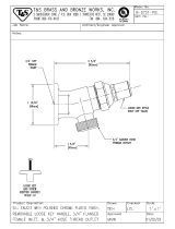
The static mixer assembly (240-3122) connects to the mix manifold outlet. The 240-3122
downstream end connection is 3/8” NPS male thread.
NOTE
F1 - F5 plugs may be removed from back of valves for connection to paint circulation systems.
NOTE

EN
77-2982-R1.1 (10/2015) 15 / 62
6.1: Fluid Panel Fluid Connections
CONNECTION
NO.
DESCRIPTION CONNECTING THREAD
F0 Solvent Inlet – includes check valve 1/4” NPT female
F1 Color 1 Inlet 1/4" NPT female
F2 Color 2 Inlet 1/4" NPT female
F3 Color 3 Inlet 1/4" NPT female
F4 Color 4 Inlet 1/4" NPT female
F5 Color 5 Inlet 1/4" NPT female
B IN B Pump Inlet 1/4" NPT female
MIX Mix manifold outlet 3/8” NPS male

EN
77-2982-R1.1 (10/2015)16 / 62
7: User Interface Guide
The touch screen display is used to control GEMS. The following pages identify the various screens and
their associated controls. Read and understand this guide to properly understand and operate the GEMS
system.
7.1: Home Screen Buttons
1. Home: This button can be pushed at any
time to return the display to the Home
Screen.
2. Color: Used to perform color changes and
programmed ush sequences. Advances to
the Color Change screen. Always visible.
3. Mute: Silence a sounding alarm. This
button will NOT reset the alarm, it will only
silence it until the alarm has been reset.
4. Alarms: Advances to the alarms screen to
reset alarms or view alarm history and
help.
5. Usage: Advances to the usage and jobs
screens for paint usage totals and job
functions.
6. Prime: Advances to the Prime
screen for loading paint colors,
solvent, and hardener into the
system.
7. Settings: Advances to the settings screens
(password protected) to change system
settings and perform calibrations.
1
2
3
4
6
5
7

EN
77-2982-R1.1 (10/2015) 17 / 62
7.2: Home Screen Information
The Home Screen displays the GEMS current conditions and status. Valuable information like current ow
rate, color number, job number, ratio, pot life, pressures, and gun status are visible here.
1. Current ow rate: Flow rate (cc/minute) also
displayed on the graph below.
2. Current Color: This is the color currently
loaded. Zero (0) will be displayed if solvent is
loaded, a color change failed, or an “A only”
calibration has been performed.
3. Flow rate graph: Combination bar and scrolling
line graphs that show current and last 75
seconds of spraying. The graph freezes when
spraying stops or an alarm is triggered. The
graph scale is adjustable via system settings.
4. Usage/Job Data: Shows the current job
number and name, whether the job is active
or paused, and current color usage for the job
shown.
5. Target ratio: the programmed ratio of paint
resin (A) to hardener (B)
6. Measured ratio: The ratio calculated by
comparing the motion of the B pump to the ow
rate of paint resin through the ow meter.
7. B Pump inlet pressure: Monitors the inbound
supply pressure to the B pump from the
hardener supply.
8. B Pump Outlet Pressure: Monitors the
outbound pressure from the B pump to the mix
manifold. Note: The upper and lower pressure
transducers alternate inlet / outlet function
depending on the direction of the B pump piston.
9. Gun status: Shows if gun 1 or gun 2 is
currently spraying with an animation. If only 1
gun is enabled gun 2 will not be displayed.
10. Pot Life display: Display the pot life
remaining for each gun (if active).
11. Background Color: The background color will
be white until an alarm is triggered, when it will
change to ashing yellow.
12. USB Status: Indicates if USB ash drive is
installed.
13. Current time and date: Local system name,
time, and date.
14. Current screen icon: Icon showing which
screen is currently shown
1
6
9
4
7
5
8
10
11
13
3
2
12
14

EN
77-2982-R1.1 (10/2015)18 / 62
7.3: Color Change Screen
Only this screen and the Home screen are accessed directly from every screen of the display. It is used
for changing colors and ushing the system with the ush / load sequences programmed in the settings
screens.
1. Current/ Active Color: The current color
loaded in the system.
2. New Color: This is the eld where the new
color number to load is entered. Tap in the box
to enter a new color number. The popup below
will appear for color number entry.
3. Stop: Stop the color change process. Only
visible after GO is selected. Selecting this
will trigger a Color Change alarm.
4. 1 Gun GO: Starts the ush / load
process for gun #1 only. The color #
entered in the New Color eld will be
loaded.
5. 2 Gun GO: Starts the ush / load
process for gun #1 and gun #2.
The color # entered in the New
Color eld will be loaded. Only
available if the system is congured
for 2 guns and both guns are
enabled.
6. Batch: Advances to the Batch screen. Only
visible if a color other than 0 is loaded. See
section 7.11 for Batch screen details.
2
4
1
5
3
6

EN
77-2982-R1.1 (10/2015) 19 / 62
7.4: Usage Screen
This screen tracks the global usage of resin and hardener, sorted by color number. If the solvent meter
is installed the solvent usage will be visible at the bottom of this list. For additional information regarding
Jobs, see 8.22: Job Advance.
1. Resin (A): The total volume of paint
resin dispensed for each color. Measured
in cc’s.
2. Hardener (B): The total volume of
paint hardener dispensed for each color.
Measured in cc’s.
3. Jobs: Advances to the Jobs screen. See
section 7.10 for Jobs screen details.
4. Reset: Resets usage totals. Note this
action requires the Administrator
password. Tap on the desired A or B box
for the color # to reset; the color
selected will be highlighted with a
yellow/grey border as shown above.
Tap the reset button to reset totals for
the selected color number.
The clear/reset command is only accepted if the Administrator password is provided.
NOTE
1
2
3
4

EN
77-2982-R1.1 (10/2015)20 / 62
7.5: Prime Screen
Use this screen to prime the GEMS unit with Resin (A) and Hardener (B). Buttons will independently
operate the Resin color valves (A0-A7), or the B Pump for material loading. Gun atomizing air must be off
while priming. For resin priming, the active color valve will blink yellow for easy recognition.
1. Color Valve: The icon displaying which color
valve is being opened when pressed.
• Color 0 is reserved for ushing solvent
• Colors 1-5 are for A material (resins)
• Color 7 is reserved for ushing air
2. Color Stack Prime: Press the button
once to open the AE and selected color
valve. Trigger the spray gun with
atomizing air off to allow resin to ow.
Press the button again to stop.
3. B Pump Prime: When pressed, the
B Pump valves will open, and the
Pump will cycle. The gun must be
triggered with atomizing air off for
successful component B priming.
Press the button again to stop.
4. Flush Mode: Use the Flush button to
put the system in a continuous air/
solvent chop process for ushing. It
will timeout after 5 minutes.
1
2
3 4
Always follow the Prime mode with a color 0 (solvent) load to flush out the fluid lines and
prevent unmixed material from being sprayed or hardening in the system.
!
CAUTION
/