Page is loading ...

EN
77-3089-R1.0 (8/2015) 1 / 6
OPERATION MANUAL
240-3113 SOLVENT METER KIT
INSTALLATION INSTRUCTIONS
GLOBAL ELECTRONIC MIX SOLUTIONS
PLURAL COMPONENT MIXING SYSTEM

EN
77-3089-R1.0 (8/2015)2 / 6
Binks reserves the right to modify equipment specification without prior notice.
LOCK OUT / TAG-OUT
Failure to de-energize, disconnect, lock out and tag-out all power
sources before performing equipment maintenance could cause
serious injury or death.
OPERATOR TRAINING
All personnel must be trained before operating finishing
equipment.
EQUIPMENT MISUSE HAZARD
Equipment misuse can cause the equipment to rupture,
malfunction, or start unexpectedly and result in serious injury.
PROJECTILE HAZARD
You may be injured by venting liquids or gases that are released
under pressure, or flying debris.
PINCH POINT HAZARD
Moving parts can crush and cut. Pinch points are basically any
areas where there are moving parts.
INSPECT THE EQUIPMENT DAILY
Inspect the equipment for worn or broken parts on a daily basis.
Do not operate the equipment if you are uncertain about its
condition.
In this part sheet, the words WARNING, CAUTION and NOTE are used to
emphasize important safety information as follows:
Hazards or unsafe practices which
could result in minor personal injury,
product or property damage.
!
CAUTION
Hazards or unsafe practices which
could result in severe personal
injury, death or substantial property
damage.
!
WARNING
Important installation, operation or
maintenance information.
NOTE
Read the following warnings before using this equipment.
READ THE MANUAL
Before operating finishing equipment, read and understand all
safety, operation and maintenance information provided in the
operation manual.
WEAR SAFETY GLASSES
Failure to wear safety glasses with side shields could result in
serious eye injury or blindness.
NEVER MODIFY THE EQUIPMENT
Do not modify the equipment unless the manufacturer provides
written approval.
IT IS THE RESPONSIBILITY OF THE EMPLOYER TO PROVIDE THIS INFORMATION TO THE OPERATOR OF THE EQUIPMENT.
FOR FURTHER SAFETY INFORMATION REGARDING THIS EQUIPMENT, SEE THE GENERAL EQUIPMENT SAFETY BOOKLET (77-5300).
KNOW WHERE AND HOW TO SHUT OFF THE EQUIPMENT
IN CASE OF AN EMERGENCY
PRESSURE RELIEF PROCEDURE
Always follow the pressure relief procedure in the equipment
instruction manual.
NOISE HAZARD
You may be injured by loud noise. Hearing protection may be
required when using this equipment.
STATIC CHARGE
Fluid may develop a static charge that must be dissipated through
proper grounding of the equipment, objects to be sprayed and all
other electrically conductive objects in the dispensing area. Improper
grounding or sparks can cause a hazardous condition and result in
fire, explosion or electric shock and other serious injury.
PROP 65 WARNING
WARNING: This product contains chemicals known to the
State of California to cause cancer and birth defects or other
reproductive harm.
WEAR RESPIRATOR
Toxic fumes can cause serious injury or death if inhaled.
Wear a respirator as recommended by the fluid and solvent
manufacturer’s Material Safety Data Sheet.
TOXIC FLUID & FUMES
Hazardous fluid or toxic fumes can cause serious injury or death if
splashed in the eyes or on the skin, inhaled, injected or
swallowed. LEARN and KNOW the specific hazards or the fluids
you are using.
KEEP EQUIPMENT GUARDS IN PLACE
Do not operate the equipment if the safety devices have been
removed.
!
WARNING
AUTOMATIC EQUIPMENT
Automatic equipment may start suddenly without warning.
FIRE AND EXPLOSION HAZARD
Improper equipment grounding, poor ventilation, open flame or
sparks can cause a hazardous condition and result in fire or
explosion and serious injury.
PLURAL COMPONENT MATERIALS HAZARD
Because of the vast number of chemicals that could be used and
their varying chemical reactions, the buyer and user of this
equipment must determine all facts relating to the materials used,
including any of the potential hazards involved.
ELECTRIC SHOCK / GROUNDING
Improper grounding or sparks can cause a hazardous condition
and result in fire, explosion or electric shock and other serious
injury.
HIGH PRESSURE CONSIDERATION
High pressure can cause serious injury. Relieve all pressure before
servicing. Spray from the spray gun, hose leaks, or ruptured
components can inject fluid into your body and cause extremely
serious injury.
EXPLOSION HAZARD
Halogenated hydrocarbon solvents can cause an explosion when
in contact with aluminum components of a pressurized or closed
fluid system.

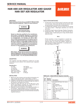
New Solvent Inlet
EN
77-3089-R1.0 (8/2015) 3 / 6
Installation
To install the solvent meter kit, be sure to rst depressurize the GEMS system and disconnect electric
power. For more information regarding this procedure, see 1.1: System Depressurization Procedure
of the Maintenance and Repair Manual 77-2983. Never attempt to touch any electrical componentry
when power is supplied.
Solvent Meter Accessory Kit
The solvent ow meter is used to measure solvent usage during color changes and ushes. The ow meter is
the same as used to measure paint ow, and is installed upstream of the color 0 valve and the color stack.
The solvent meter must be enabled in the system configuration, accessible only by distributor.
Contact distributor for installation and proper kit functionality.
!
CAUTION
Use the supplied screws to mount the supplied bracket to the
ow meter body as shown. Mount the bracket to the uid panel
using the supplied mounting screws, washers and nuts. Note the
ow direction arrow on the solvent meter should be pointing up—
opposite the paint meter.
Route the associated tubing form the solvent meter up to
the solvent valve (A0) and connect it to the existing elbow
tting. The bottom of the ow meter is now the solvent inlet
to the system. Attach solvent supply to 3/8” NPS male tting.
If necessary, cut tube to appropriate length before
tightening ferrule and tting to solvent inlet.

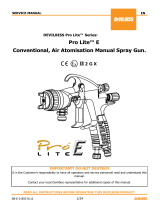
#308
#275
EN
77-3089-R1.0 (8/2015)4 / 6
Open the enclosure door. Remove one of the pre-installed plugs
from one three unused strain reliefs. This is where the wire harness
will enter the control enclosure. Unscrew the strain relief end nut
and feed the ow meter cable through it into the cabinet.
Remove the wire tray covers and route the wiring
through the wire tray before connecting wiring.
The white wire #308 connects into the board
terminal location L3C1 (shown below). Tighten
the terminal screw so the wire will not slip out
once installed.
Black wire #275 connects to L3C10 - DCC on the board input. Red wire #216
(#218 if Intrinsically Safe option used) connects to the C13 terminal block.

EN
77-3089-R1.0 (8/2015) 5 / 6
Route the cable through both wire trays before placing
the covers back in place. With the cable in place, be
sure to tighten down the nut end of the strain relief,
so the cable cannot be tugged out of position. Verify
all connections are solid and tight, and close the
enclosure door.
Route the cable connector end through the uid panel
opening to the sensor body. Connect the solvent meter
connector to the body of the ow sensor and tighten into
place. Note the connector and pickup body are keyed so
there is only one correct connector orientation.
The ow meter must be enabled in the system
conguration, accessible only by distributor. Contact
distributor for installation and proper kit functionality.
Power on the system and prime solvent through the system.
Perform a Color 0 Resin Only calibration and verify that the
measured volume matches up with the calculated volume.
If not, revise the cc/pulse value in the settings screen to the
correct amount (.123 is the default). Correct solvent usage will
be shown on the Usage and Jobs (Color Change) screens.

EN
77-3089-R1.0 (8/2015)6 / 6
Finishing Brands reserves the right to modify equipment specications without prior notice.
DeVilbiss
®
, Ransburg
®
, BGK
®
, and Binks
®
are registered trademarks of Carlisle Fluid Technologies, Inc.,
dba Finishing Brands. ©2015 Carlisle Fluid Technologies, Inc., dba Finishing Brands. All rights reserved.
WARRANTY POLICY
Binks products are covered by Finishing Brands one year materials and workmanship limited warranty.
The use of any parts or accessories, from a source other than Finishing Brands, will void all warranties.
For specic warranty information please contact the closest Finishing Brands location listed below.
Binks is part of Finishing Brands, a global leader in innovative spray nishing
technologies. For technical assistance or to locate an authorized distributor,
contact one of our international sales and customer support locations below.
USA/Canada
www.binks.com
Tel: 1-800-992-4657
Fax: 1-888-246-5732
United Kingdom
www.nishingbrands.eu
Tel: +44 (0)1202 571 111
Fax: +44 (0)1202 573 488
China
www.nishingbrands.com.cn
Tel: +8621-3373 0108
Fax: +8621-3373 0308
Mexico
www.carlisleft.com.mx
Tel: 011 52 55 5321 2300
Fax: 011 52 55 5310 4790
France
www.nishingbrands.eu
Tel: +33(0)475 75 27 00
Fax: +33(0)475 75 27 59
Japan
www.ransburg.co.jp
Tel: 081 45 785 6421
Fax: 081 45 785 6517
Brazil
www.devilbiss.com.br
Tel: +55 11 5641 2776
Fax: 55 11 5641 1256
Germany
www.nishingbrands.eu
Tel: +49 (0) 6074 403 1
Fax: +49 (0) 6074 403 281
Australia
www.nishingbrands.com.au
Tel: +61 (0) 2 8525 7555
Fax: +61 (0) 2 8525 7500
/