Page is loading ...

The following instructions provide the necessary
information for the proper operation and preventive
maintenance of the Binks Model 21 Automatic Spray
Gun. Please read and understand all information in this
document in order to get the maximum performance from
your new Model 21 spray gun.
The Model 21 Series of spray guns are heavy duty,
pneumatically operated, automatic spray guns with forged
brass bodies.
All Model 21 spray guns feature nickel plated brass air
caps and bodies that will withstand years of use under the
toughest conditions. The Model 21V spray guns contain
tungsten carbide fluid nozzles and needles for use with
abrasive fluids. The Model 21M spray guns are internal
mix spray guns used in line striping.
SPECIFICATIONS:
Maximum
Fluid Pressure: 100 psi/6.9 bar
Maximum
Air Pressure: 100 psi/6.9 bar
Gun Body: Plated Brass
Fluid Path: Brass/Electroless Nickle Plated
Fluid Inlet Size: 3/8" NPS(m) Thread
Air Inlet Size: 1/4" NPS(m) Thread
Gun Weight: 41 oz./1213 g
Mounting Hole: 1/2"
Mounting Bracket: 54-380
(1/2" Bar)
READ ALL INSTRUCTIONS BEFORE OPERATING THIS BINKS PRODUCT
IMPORTANT!
DO NOT DESTROY
It is the customer's responsibility to have
all operators and service personnel read
and understand this manual.
Contact your local Binks representative
for additional copies of this manual.
PROP 65 WARNING
WARNING: This product contains chemicals known to
the State of California to cause cancer and birth
defects or other reproductive harm.
MODEL 21, 21V, & 21M
AUTOMATIC SPRAY GUN
(6220-XXXX-X) (6235-XXXX-X) (6219-XXXX-X)
BRASS BODY
77-2976-R4 (3/2018) 1 / 12 www.carlisleft.com
EN
SERVICE MANUAL

Read the following warnings before using this equipment.
READ THE MANUAL
Before operating finishing equipment, read and
understand all safety, operation and maintenance
information provided in the operation manual.
AUTOMATIC EQUIPMENT
Automatic equipment may start suddenly without
warning.
INSPECT THE EQUIPMENT DAILY
Inspect the equipment for worn or broken parts
on a daily basis. Do not operate the equipment
if you are uncertain about its condition.
NEVER MODIFY THE EQUIPMENT
Do not modify the equipment unless the
manufacturer provides written approval.
KNOW WHERE AND HOW TO SHUT OFF THE
EQUIPMENT IN CASE OF AN EMERGENCY
PRESSURE RELIEF PROCEDURE
Always follow the pressure relief procedure in the
equipment instruction manual.
NOISE HAZARD
You may be injured by loud noise. Hearing
protection may be required when using this
equipment.
HIGH PRESSURE CONSIDERATION
High pressure can cause serious injury. Relieve all
pressure before servicing. Spray from the spray
gun, hose leaks, or ruptured components can
inject fluid into your body and cause extremely
serious injury.
STATIC CHARGE
Fluid may develop a static charge that must be
dissipated through proper grounding of the
equipment, objects to be sprayed and all other
electrically conductive objects in the dispensing
area. Improper grounding or sparks can cause a
hazardous condition and result in fire, explosion
or electric shock and other serious injury.
WEAR SAFETY GLASSES
Failure to wear safety glasses with side shields
could result in serious eye injury or blindness.
OPERATOR TRAINING
All personnel must be trained before operating
finishing equipment.
EQUIPMENT MISUSE HAZARD
Equipment misuse can cause the equip ment to
rupture, malfunction, or start unexpectedly and
result in serious injury.
KEEP EQUIPMENT GUARDS IN PLACE
Do not operate the equipment if the safety
devices have been removed.
PROJECTILE HAZARD
You may be injured by venting liquids or gases
that are released under pressure, or flying debris.
PINCH POINT HAZARD
Moving parts can crush and cut. Pinch points are
basically any areas where there are moving parts.
DE-ENERGIZE, DEPRESSURIZE, DISCONNECT
AND LOCK OUT ALL POWER SOURCES DURING
MAINTENANCE
Failure to De-energize, disconnect and lock out
all power supplies before performing equipment
maintenance could cause serious injury or death.
FOR FURTHER SAFETY INFORMATION REGARDING BINKS AND DEVILBISS EQUIPMENT, SEE THE
GENERAL EQUIPMENT SAFETY BOOKLET (77-5300).
IT IS THE RESPONSIBILITY OF THE EMPLOYER TO PROVIDE THIS INFORMATION TO THE OPERATOR OF THE EQUIPMENT.
PROP 65 WARNING
WARNING: This product contains chemicals known
to the State of California to cause cancer and
birth defects or other reproductive harm.
CA PROP
65
WARNING
!
In this part sheet, the words WARNING, CAUTION and NOTE are used to emphasize important safety information as follows:
CAUTION
Hazards or unsafe practices which could
result in minor personal injury, product
or property damage.
!
WARNING
Hazards or unsafe practices which could
result in severe personal injury, death or
substantial property damage.
!
NOTE
Important installation, operation or
maintenance information.
EN
77-2976-R4 (3/2018)2 / 12www.carlisleft.com

BINKS MODEL 21 & 21V SERIES AUTOMATIC SPRAY GUN
HOOK-UP
1. Air pressure of 35-50 PSI minimum required for cylin-
der operation.
2. For rapid operation, the air line between three-way
valve and the cylinder operating air connection should
be as short as possible.
3. All air supplied to the gun should be dirt and moisture-
free. A DeVilbiss centrifugal air filter mounted in the
air supply line is recommended.
4. If the gun is to stand idle for any length of time, shut
off. This will prevent small leaks throughout the
system from turning on the gun.
FAN SPRAY ADJUSTMENTS
The fan spray is easily controlled by means of the side
port control. Turning this control to the right, or clock-
wise, will give a round spray pattern. Turning it to the
left, or counter-clockwise, will widen the spray into a fan
shape of any desired width. Orientation of the fan spray
either horizontally or vertically (or to any position in
between) is obtained by loosening the retainer ring, rotat-
ing the air nozzle to the desired position, and then tight-
ening the retainer ring.
FLUID FLOW ADJUSTMENTS
For best results, the fluid control screw (16) should be set
at the open position and the flow of the fluid controlled
by regulating the fluid pressure in the pressure tank. If
the conditions under which the gun is being used require
the fluid to be controlled at the gun, it may be accom-
plished by loosening locknut (17) and turning screw (16)
to the right (clockwise) to decrease the flow of fluid or
the left (counter-clockwise) to increase the flow of fluid.
LUBRICATION
The points that require lubrication on this gun are the
plunger (7), the air valve packing (11), and the fluid
packing (29). These parts should be kept soft and pliable
at all times. SSL-10 gun lube is recommended for this.
CLEANING
Shut off the air supply to the tank and release its pressure.
Hold a piece of wadded cloth over the gun nozzle and
turn on the air to the cylinder. The air will back up
through the fluid nozzle and force fluid out of the hose
and into the tank.
Replace the paint in the pressure tank with clean solvent
and flush through the material hose and spray gun until
clean. Blow air through the fluid hose to eliminate
residual solvent. Always follow EPA and NFPA
regulations when spraying or cleaning spray equipment.
FAULTY SPRAY
Faulty spray is caused by dry coating material residue
around the fluid nozzle tip or inside the air nozzle. Soak
these parts in a solvent that will soften the dried residue
until it can be removed with a brush or a cloth.
!
CAUTION
Never submerge the gun in solvent. Solvent will wash the
oil off the lubricated parts and cause subsequent malfunc-
tioning of the gun.
!
CAUTION
Never use metal probes to clean the air or fluid nozzles
because scratches and burns on their precision machined
surfaces can cause faulty spray. If either the air or fluid
nozzle is damaged so as to give faulty spray, it must be
replaced.
Note: 21 and 21V Gun spray patterns can be adjusted
from round spray to maximum pattern size by the
means of the side port adjustment.
Model 21 Model 21V
Model 21M
New Setups
Use for Line Striping
6220-2800-7
63BSS-63PB
■ ■ ■ ■ 0.046 1.2 14 9.0 14.3 20.0
6220-4307-9
66SS-66SD
■ ■ ■ ■ 0.070 1.8 10.5 7.9 12.1 15.5
6220-8118-5
59BSS-252
■ 0.218 5.5 6 7.8 11.5 15.2
6220-2821-1 63BSS-21MD-1
■ ■ ■ ■ 0.046 1.2 14 8.5 12.3 15.9
6220-2821-3
63BSS-21MD-3
■ ■ 0.046 1.2 15 8.4 12.2 15.7
6220-4308-2
66SS-66SD-3
■ 0.070 1.8 10 7.9 12.1 16.2
6220-5123-7
68SS-709SS
■ 0.110 2.8 6 4.3 6.9 8.9
6220-8219-1
59CSS-262
■ 0.281 7.1 6 7.3 11.0 14.7
6235-4921-2
67VT-21MD-2
■ ■ ■ ■ 0.086 2.2 17 9.6 14.0 18.1
6235-3206-3
63CVT-66PH
■ ■ ■ 0.052 1.3 11 8.0 11.8 15.2
6235-4909-5
67VT-67PB
■ ■ ■ ■ 0.086 2.2 12 9.5 14.1 19.1
6219-8219-1 59CSS-262
Internal mix spray gun for line striping applications
Thin
Medium
Heavy
Very Heavy
Adhesives
Mold Release
Ceramics
Non-Stick Coating
Hammers
Zinc
Fluid Orifice
Size (inches)
Fluid Orifice
Size (mm)
Pattern Size
Max at 8"
CFM at
30 PSI
CFM at
50 PSI
CFM at
70 PSI
MODEL 21
SETUPS AVAILABLE
5-25
centipoise
25-70
centipoise
70-115
centipoise
>115
centipoise
COMPLETE SPRAY GUN MODELS – ORDERING GUIDE
EN
77-2976-R4 (3/2018) 3 / 12 www.carlisleft.com

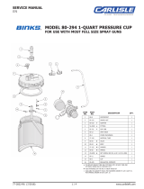
BINKS MODEL 21 & 21V SERIES AUTOMATIC SPRAY GUN
Side Port
Control
Mounting Hole
(1/2" Dia.)
Mounting
Lockscrew
Fluid Adjustment
Control
Fluid Inlet
3/8 NPS(m)
Atomizing Air Inlet
1/4 NPS(m)
Cylinder
Operating
Air Inlet
1/4 NPS(m),
(35-50 PSI Min.)
For multiple gun installation, a fluid manifold may be used.
Fluid adjustments are made using the fluid control screw on
each gun. However, when precise fluid control is necessary,
a fluid regulator for each gun must be used.
Fluid
Cylinder Air
Cylinder Air
(From Extractor)
3-Way Valve
Atomizing Air
(From Extractor)
To Fluid Supply
Shut-Off Cocks
Atomizing Air
MODEL 21M
BINKS
THREE WAY VALVE OR
TRIGGERING DEVICE
COMPRESSED AIR SUPPLY
COMPRESSED AIR SUPPLY
THREE WAY VALVE
OIL AND WATER EXTRACTOR
PRESSURE TANK
SOLVENT FLUSH LINE
ATOMIZING AIR SUPPLY
CYLINDER AIR SUPPLY
FLUID SUPPLY
BINKS
MODEL 21
BINKS
MODEL 21
BINKS
MODEL 21
Fluid Supply
Atomizing Air
Cylinder Air
Three Way
Valve or
Triggering
Device
Oil and Water Extractor
Compressed Air Supply
Typical Pump
with Container
Pump Air
Supply
GENERAL NOTES
1. Have at least 35 PSI air pressure for cylinder operating air.
2. The air line from spray gun to 3-way valve should be as
short as possible for rapid operation.
3. All air used in the spray gun should be dirt and moisture
free. (This is accomplished by using a clean air filter.)
4. Shut off all fluid and air lines to spray gun if spray gun is
to stand idle for any length of time. (This is to prevent
"build-up" or accumulation of minute leaks in the system.)
5. Generally fluid hoses are 3/8" and air hoses are 1/4".
BINKS SPRAY
GUN MODEL
CONNECTION THREADS SIZE
FLUID AIR
21 SERIES 3/8 NPS 1/4 NPS
MODEL 21M
BINKS
THREE WAY VALVE OR
TRIGGERING DEVICE
COMPRESSED AIR SUPPLY
COMPRESSED AIR SUPPLY
THREE WAY VALVE
OIL AND WATER EXTRACTOR
PRESSURE TANK
SOLVENT FLUSH LINE
ATOMIZING AIR SUPPLY
CYLINDER AIR SUPPLY
FLUID SUPPLY
BINKS
MODEL 21
BINKS
MODEL 21
BINKS
MODEL 21
Fluid
Atomizing
Air
Cylinder Air
Three Way
Valve or
Triggering
Device
Oil and Water
Extractor
Compressed Air
Supply
Air Compressor
Pressure
Tank
EN
77-2976-R4 (3/2018)4 / 12www.carlisleft.com

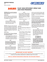
BINKS MODEL 21 & 21V SERIES AUTOMATIC SPRAY GUN
1
2
4
5
6
7
8
9
10
11
12 12
13
14
3
15
16
17
18
19
20
21
22
23
24
25
26
27
28
29
30
31
ITEM PART
NO. NO. DESCRIPTION QTY.
1 ❍ NOZZLE Air .................................. 1
2 ❍ NOZZLE Fluid ................................ 1
3 ■ FLUID NEEDLE ............................. 1
4 54-232 LOCKNUT Plunger ......................... 1
5 54-233 WASHER Plunger .......................... 1
6 54-236 SPRING Plunger ............................. 1
7 54-261• PLUNGER Leather.......................... 1
8
▲
54-302 GLAND Packing ............................ 1
❋
54-440
9 54-304-5• SPRING Packing Follower ......(Kit of 5) 1
10 54-306 NUT Air Packing ............................ 1
11 54-307-5• PACKING Air .....................(Kit of 5) 1
12 54-308 CONNECTION Air ......................... 2
13 54-310-5• PACKING Air Valve .............(Kit of 5) 1
14 54-312 GUIDE Air Valve ............................. 1
15 54-321 BONNET ...................................... 1
16 ● 54-6003 SCREW Fluid Control ...................... 1
17 54-323 LOCKNUT FLUID CONTROL ........ 1
18 54-324 WASHER Fluid Control Locknut ........ 1
19 54-329• WASHER Side Port Control .............. 1
20 54-330• SPRING Side Port Control ................. 1
ITEM PART
NO. NO. DESCRIPTION QTY.
21 54-331• PIN Side Port Control ....................... 1
22 54-332• FOLLOWER Side Port Control .......... 1
23 54-333 SIDE PORT CONTROL Complete .... 1
24
▲
54-334-5 FOLLOWER Packing ...........(Kit of 5) 1
❋
54-446 (Single Piece)
25 54-335 SCREW Set ................................... 1
26
▲
54-337 VALVE Air ..................................... 1
❋
54-444
27 54-728-5 SPRING Needle Valve ...................... 1
28 54-738-5• PACKING Side Port Control .............. 1
29
▲
2-28-5• PACKING Needle Valve ........(Kit of 5) 1
❋
54-1339 (Single Piece)
30
▲
54-765 NUT Packing .................................. 1
❋
54-1353
31 54-918-5• GASKET Fluid Nozzle (Kit of 5) ......... 1
32 OMX-88 BRUSH Cleaning (Not Shown) ........... 1
33 54-6001 SPACER SPRING ............................. 1
34 54-5522 VALVE UMBRELLA .......................... 1
35 ✩ 54-6004 (OPTIONAL) MOUNTING
BRACKET ASSEMBLY ...................... 1
36 54-4270 NEEDLE COVER ........................... 1
PARTS LIST
When ordering, please specify Part No.
❍ When ordering, please specify number stamped on nozzle.
■ When ordering, please specify gun model and number stamped on needle.
• Parts also available in Repair Kit 6-191.
Gun wrench, 5-476 is recommended for removing fluid nozzle. Please order separately.
● Includes Item 34.
▲ 21 spray gun only.
❋ 21V spray gun only.
✩ Allows for easy gun change while
maintaining gun alignment.
34
33
35
✩
36
EN
77-2976-R4 (3/2018) 5 / 12 www.carlisleft.com

BINKS MODEL 21 & 21V SERIES AUTOMATIC SPRAY GUN
INTERNAL MIX HEAVY MATERIAL NOZZLES (OPTIONAL)
FLUID NOZZLE AND NEEDLE ORDERING GUIDE
FLUID NOZZLE
MARKING
ORDER PART
NUMBER
NEEDLE
MARKING
ORDER NEEDLE
NUMBER
ORIFICE SIZE
INCHES (MM)
MATERIAL
59ASS 45-5911 259 47-25900 .171 (4.3) Stainless Steel
59BSS 45-5912 259 47-25900 .218 (5.5) Stainless Steel
59CSS 45-5913 259 47-25900 .281 (7.7) Stainless Steel
63BSS 45-6321 263A 47-26310 .046 (1.2) Stainless Steel
66SS 45-6601 265 47-26500 .070 (1.8) Stainless Steel
68SS 45-6801 268 47-26800 .110 (2.8) Stainless Steel
63CVT 45-6332 263CVT 47-26332 .052 (1.3) Tungsten Carbide
67VT 45-6702 267VT 47-26702 .086 (2.2) Tungsten Carbide
68VT 45-6802 268VT 47-26802 .110 (2.8) Tungsten Carbide
AIR CAP ORDERING GUIDE
AIR CAP
MARKING
ORDER PART
NUMBER
AIR CAP
MARKING
ORDER PART
NUMBER
200 46-2200 66PH 46-6016
252 46-2252 66SD 46-6020
262 46-2262 66SD-3 46-6092
21MD-1 46-21MD-1 66SK 46-6082
21MD-2 46-21MD-2 67PB 46-6026
21MD-3 46-21MD-3 68PB 46-6032
63PB 46-6002 709SS 46-2020
NOZZLE TIP*
NITRALLOY
200
NOZZLE BASE
WITH RING
54-372
AIR NOZZLE*
NITRALLOY
252, 262
AIR NOZZLE*
706, 709SS
FLUID NOZZLE*
59ASS, 59BSS, 59CSS
259 NEEDLE ASSEMBLY
AIR NOZZLE ASSEMBLY*
* When ordering please specify number
stamped on nozzle.
54-1584
54-2065
54-1583
EN
77-2976-R4 (3/2018)6 / 12www.carlisleft.com

MODEL 21 NOZZLE AND NEEDLE SELECTION CHARTS
TYPE OF FLUID TO BE SPRAYED
FLUID X AIR
NOZZLES
FLUID
NEEDLE
GUN PART
NUMBER
CFM @
30 PSI
CFM @
50 PSI
CFM @
70 PSI
MAX
PATTERN
@ 8”
THIN, 5-25 CENTIPOISE
wash primers, dyes, stains, solvents,
water, inks, sealers, laquers, lubricants,
zinc chromates, acrylics
63BSS X 63PB 263A 6220-2800-7 9.0 14.3 20.0 14
66SS X 66SD 265 6220-4307-9 7.9 12.1 15.5 10.5
63BSS X 21MD-1 263A 6220-2821-1 8.5 12.2 15.9 14
63CVT X 66PH 263CVT 6235-3206-3 8.0 11.8 15.2 11
66SS X 66SK 265 * 11.0 15.2 19.5 13
63BSS X 200 263A * 3.1 5.2 6.4 12
MEDIUM, 25-70 CENTIPOISE
synthetic enamels, varnishes, shellacs,
fillers, primers, epoxies, urethanes,
lubricants, wax emulsions, enamels
63BSS X 63PB 263A 6220-2800-7 9.0 14.3 20.0 14
66SS X 66SD 265 6220-4307-9 7.9 12.1 15.5 10.5
63BSS X 21MD-1 263A 6220-2821-1 8.5 12.3 15.9 14
63BSS X 21MD-3 263A 6220-2821-3 8.4 12.2 15.7 15
67VT X 21MD-2 267VT 6235-4921-2 9.6 14.0 18.1 17
63CVT X 66PH 263CVT 6235-3206-3 8.0 11.8 15.2 11
67VT X 67PB 267VT 6235-4909-5 9.5 14.1 19.1 12
66SS X 66SK 265 * 11.0 15.2 19.5 13
HEAVY, 70-115 CENTIPOISE
63BSS X 21MD-1 263A 6220-2821-1 8.5 12.3 15.9 14
63BSS X 21MD-3 263A 6220-2821-3 8.4 12.2 15.7 15
68SS X 709SS 268 6220-5123-7 4.3 6.9 8.9 6
67VT X 21MD-2 267VT 6235-4921-2 9.6 14.0 18.1 17
67VT X 67PB 267VT 6235-4909-5 9.5 14.1 19.1 12
68SS X 68PB 268 * 9.5 14.1 19.1 12
VERY HEAVY, >115 CENTIPOISE
texture coating, road marking paint
59BSS X 252 259 6220-8118-5 7.8 11.5 15.2 6
59CSS X 262 259 6220-8219-1 7.3 11.0 14.7 6
68SS X 68PB 268 * 9.5 14.1 19.1 12
ADHESIVES
waterbase vinyl glues, solvent base,
neoprenes, contact cement
66SS X 66SD-3 265 6220-4308-2 7.9 12.1 16.2 10
63BSS X 66SD-3 263 * 7.9 12.1 16.2 4
MOLD RELEASE 63BSS X 63PB 263A 6220-2800-7 9.0 14.3 20.0 14
CERAMICS
similar abrasive materials, glazes,
engobes, porcelain enamel
67VT x 21MD-2 267VT 6235-4921-2 9.6 14.0 18.1 17
67VT X 67PB 267VT 6235-4909-5 9.5 14.1 19.1 12
68VT X 68PB 268VT * 9.5 14.1 19.1 12
CONCRETE CURING COMPOUNDS 66SS X 200 265 * 3.1 5.2 6.4 15
MULTICOLOR PAINTS 66SS X 200 265 * 3.1 5.2 6.4 15
NON-STICK COATINGS
63BSS X63PB 263A 6220-2800-7 9.0 14.3 20.0 14
66SS X 66SD 265 6220-4307-9 7.9 12.1 15.5 10.5
63BSS X 21MD-1 263A 6220-2821-1 8.5 12.3 15.9 14
63CVT X 66PH 263CVT 6235-3206-3 8.0 11.8 15.2 11
HAMMERS
66SS X 66SD 265 6220-4307-9 7.9 12.1 15.5 10.5
66SS X 63PB 265 * 9.0 14.3 – 9.0
WRINKLE ENAMELS 66SS X 63PB 265 * 9.0 14.3 20.0 10.0
ZINC RICH COATINGS
67VT x 21MD-2 267VT 6235-4921-2 9.6 14.0 18.1 17
67VT X 67PB 267VT 6235-4909-5 9.5 14.1 19.1 12
Set ups for vitreous/abrasive materials (Tungsten Carbide needles and fluid nozzles.)
* Set ups available as spares only.
200, 709SS, 252, & 262 are internal mix air caps.
EN
77-2976-R4 (3/2018) 7 / 12 www.carlisleft.com

BINKS MODEL 21M
AUTOMATIC SPRAY GUN
(6219-8219-1)
The Binks Model 21M is designed to deal with rough
environments both inside and outside the spray gun.
The Binks 21M spray gun will stand up to any line
striping process. The internal mix air cap keeps the
spray pattern precise while the quick actuating air valve
ensures material is only sprayed where and when you
want it. The standard model includes a 0.281" orifice
for heavy viscosity materials and an air cap that sprays
up to a 7" pattern.
The Model 21M has the capability to quick flush the air
and fluid nozzles, making it perfect for line striping
trucks. The diagram below shows the setup required for
a quick flush.
Three Way Valve
Fluid Regulator
Solvent Flush Line
Oil and Water Extractor
Atomizing Air Supply
Cylinder Air Supply
Fluid Supply
Compressed Air Supply
Three Way Valve or
Triggering Device
EN
77-2976-R4 (3/2018)8 / 12www.carlisleft.com

BINKS MODEL 21M (BRASS BODY) AUTOMATIC ROADMARKING SPRAY GUN
ITEM PART
NO. NO. DESCRIPTION QTY.
1 45-5913 FLUID NOZZLE 59CSS (Standard) .... 1
2 46-2262 AIR NOZZLE 262 (Standard) ............ 1
3 47-25900 NEEDLE VALVE ASSEMBLY 259 ... 1
4 54-232▲ NUT ............................................... 1
5 54-233▲ WASHER ....................................... 1
6 54-236 PISTON SPRING ............................ 1
7 54-261▲ PLUNGER ...................................... 1
8 54-302
•
GLAND .......................................... 1
9 54-304-5 SPRING ...............................(Kit of 5) 1
10 54-306 PACKING NUT .............................. 1
11 54-307-5 PACKING ............................ (Kit of 5) 1
12 54-308 AIR CONNECTION ........................ 2
13 54-310-5 PACKING ............................ (Kit of 5) 1
14 54-312 GUIDE ........................................... 1
15 54-321 BONNET ........................................ 1
16 54-6003 ■ CONTROL SCREW ......................... 1
17 54-323 CONTROL SCREW LOCKNUT ....... 1
18 54-324 WASHER ....................................... 1
ITEM PART
NO. NO. DESCRIPTION QTY.
19 54-334-5 PACKING FOLLOWER ........(Kit of 5) 1
20 54-335 SET SCREW ................................... 1
21 54-337▲ VALVE ........................................... 1
22 54-495 PLUNGER ASSEMBLY ................... 1
23 54-496 PACKING BOX ASSEMBLY ........... 1
24 54-542 LOCKNUT (Part of Item No. 3) ........... 1
25 54-763 LOCKNUT (Part of Item No. 3) ........... 1
26 2-28-5
•
PACKING ............................(Kit of 5) 1
27 54-765
•
NUT ............................................... 1
28 54-839 NEEDLE VALVE SPRING ................ 1
29 54-918-5 AIR NOZZLE GASKET ........(Kit of 5) 1
30 54-2065 RETAINER RING ............................ 1
31 OMX-88 BRUSH (NOT SHOWN) ................. 1
32 54-6001 SPACER SPRING ............................... 1
33 54-5522 VALVE UMBRELLA............................ 1
34 ✩ 54-6004 (OPTIONAL) MOUNTING
BRACKET ASSEMBLY ....................... 1
35 54-4270 (OPTIONAL) NEEDLE COVER ....... 1
PARTS LIST
When ordering, please specify Part No.
▲ Part of 54-495 plunger assembly.
•
Part of 54-496 packing box assembly.
■ Includes Item 33.
✩ Allows for easy gun change while
maintaining gun alignment.
Gun Wrench 5-476 is recommended for removing
fluid nozzle. Please order separately.
No repair kit available. Please order parts
separately.
30
2
1
24
25
3
28
32
33
10
13
14
15
16
17
20
19
26
27
23
18
9
8
7
6
5
4
11
12
2
21
22
12
1
30 29
3
244 (optional) (46-2244)
252 (optional) (46-2252)
262 (standard) (46-2262)
59ASS (optional) (45-5911)
59BSS (optional) (45-5912)
59CSS (standard) (45-5913)
259 Needle Assembly
(47-25900)
34
✩
EN
77-2976-R4 (3/2018) 9 / 12 www.carlisleft.com

NOTES
EN
77-2976-R4 (3/2018)10 / 12www.carlisleft.com

NOTES
EN
77-2976-R4 (3/2018) 11 / 12 www.carlisleft.com

EN
77-2976-R4 (3/2018)12 / 12www.carlisleft.com
WARRANTY POLICY
This product is covered by Carlisle Fluid Technologies’ materials and workmanship limited warranty.
The use of any parts or accessories, from a source other than Carlisle Fluid Technologies,
will void all warranties. Failure to reasonably follow any maintenance guidance provided
may invalidate any warranty.
For specic warranty information please contact Carlisle Fluid Technologies.
For technical assistance or to locate an authorized distributor,
contact one of our international sales and customer support locations.
Region Industrial/Automotive Automotive Renishing
Americas
Tel: 1-800-992-4657 Tel: 1-800-445-3988
Fax: 1-888-246-5732 Fax: 1-800-445-6643
Europe, Africa,
Middle East, India
Tel: +44 (0)1202 571 111
Fax: +44 (0)1202 573 488
China
Tel: +8621-3373 0108
Fax: +8621-3373 0308
Japan
Tel: +81 45 785 6421
Fax: +81 45 785 6517
Australia
Tel: +61 (0) 2 8525 7555
Fax: +61 (0) 2 8525 7575
Carlisle Fluid Technologies is a global leader in innovative nishing technologies.
Carlisle Fluid Technologies reserves the right to modify equipment specications without prior notice.
DeVilbiss
®
, Ransburg
®
, ms
®
, BGK
®
, and Binks
®
are registered trademarks of Carlisle Fluid Technologies, Inc.
©2018 Carlisle Fluid Technologies, Inc.
All rights reserved.
For the latest information about our products, visit www.carlisleft.com
/