Page is loading ...

1
Installation instructions
802742UK V4.00 Sept 2018 - Zip HydroTap Industrial
Technical support
Tel: 0345 6 005 005 Email: [email protected].uk www.zipwater.co.uk
Installation instructions
Zip
HydroTap
The Worlds most advanced Drinking Water Appliance
Model :
IS & IT Industrial
VENTILATION
IS ESSENTIAL
READ SECTION 1
‘VENTILATION’
BEFORE YOU START

2
Installation instructions
802742UK V4.00 Sept 2018 - Zip HydroTap Industrial
Technical support
Tel: 0345 6 005 005 Email: [email protected].uk www.zipwater.co.uk
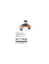
Tap options
The G4 industrial series offers a range of taps to suit the customer's needs
Command-Centre
These standalone taps are directly compatible with the
G4 Command-Centre
Boiling chilled Command-Centre for industrial models
3 button side touch
2 button top touch

3
Installation instructions
802742UK V4.00 Sept 2018 - Zip HydroTap Industrial
Technical support
Tel: 0345 6 005 005 Email: [email protected].uk www.zipwater.co.uk
Table of contents
HydroTap
G4 specifications
Installation check list .................................................................................................................... 4
General product features ............................................................................................................. 5
Important safety instructions ........................................................................................................ 6
Warnings and regulatory information ........................................................................................... 7
Major components and accessories ............................................................................................. 8
Technical specifications ............................................................................................................... 9
Before installation and site requirements ..................................................................................... 10
Installation instructions
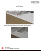
Step 1 -
Measure and cut all the tap holes before fitting the taps.
Section 1 - Tap installation.
1.1 - HydroTap
G4 generic requirements ......................................................................... 11
1.2 - HydroTap
G4 Industrial side touch installation ......................................................... 12
1.3 - HydroTap
G4 Industrial top touch installation ........................................................... 12
Step 2
- Check for adequate ventilation.
Section 2- Ventilation.
2.1- 2.2 Ventilation for all models.......................................................................................13-15
Step 3
- Install the booster (if required).
Section 3 - Booster installation.
3.1- Booster specifications and descriptions ..................................................................... 16
Pull out templates for side touch taps .................................................................................17-20
3.2- 3.4 Booster installation procedure ............................................................................. 21-22
Step 4
- Install the filter & water block (if required).
Section 4 - Filter & water block installation.
4.1- 4.2 Mounting the filter head, filter cartridge installation and flush .............................. 23
4.3- 4.8 Water block installation, reset & maintenance ..................................................... 25
Step 5
- Install the Command-Centre.
Section 5 - Command-Centre installation.
5.1- Generic installation arrangement instructions ........................................................... 26
5.2- Check the external bypass valve setting .................................................................... 27
5.3- USB connection ......................................................................................................... 28
5.4- HydroTap
G4 industrial models .................................................................................. 29
Step 6
- Commission the HydroTap
G4.
Section 6 - Commissioning.
6.1- 6.2 Generic commissioning instructions & language selection .................................. 30
6.3- Filter flush ................................................................................................................... 30
6.4- Boiling calibration ....................................................................................................... 31
6.5- Booster enable ........................................................................................................... 31
6.6- Legacy mode .............................................................................................................. 31
6.7- System flush ............................................................................................................... 32
Trouble shooting
Trouble shooting table .................................................................................................................. 33
End of life disposal ....................................................................................................................... 34
Warranty ....................................................................................................................................... 35
Contact details ............................................................................................................................. 36

4
Installation instructions
802742UK V4.00 Sept 2018 - Zip HydroTap Industrial
Technical support
Tel: 0345 6 005 005 Email: [email protected].uk www.zipwater.co.uk
Before installation
• Read the instructions and check if there is adequate space to install all of the components.
• Note Not all fittings are supplied with the appliance kit. Isolation valves are not supplied.
• Check the mains water pressure is within min / max requirements (see page 9).
• Check the water quality to determine if extra filtration will be required.
• Note This product must be fitted to a wholesome water supply.
• Check the Command Centre rating plate and ensure correct power is available.
• Check the under counter cupboard floor supporting the Command Centre is adequate for its total
weight, when full of water.
Before commissioning
• Check the system has been installed correctly.
• Check all plumbing fittings for water tightness.
• Ensure the outlet and vent pipes are positioned to drain correctly.
• Ensure there is adequate ventilation.
• Check all tubes and pipes from the Command Centre to the tap have a constant rise and there are
no sags or kinks in the hoses.
• Check all electrical connections are correct and there are no loose wires.
Commission (see section 6)
• Flush the supply line before connecting.
• Turn on the water and check for leaks.
• Flush the filter(s).
• Activate / enable the booster (if fitted).
• Where applicable, programme the Command Centre to suit the customer’s requirements.
Installation checklist

5
Installation instructions
802742UK V4.00 Sept 2018 - Zip HydroTap Industrial
Technical support
Tel: 0345 6 005 005 Email: [email protected].uk www.zipwater.co.uk
General product features
Command Centre
Thank you for purchasing a Zip HydroTap
G4. Please read and follow these instructions carefully to ensure
safe and trouble free operation. If help and advice is required, please call 0345 6 005 005.
What is the Zip HydroTap
G4 ?
This Zip HydroTap G4 is an electronically controlled, filtered, boiling and chilled water drinking system for
the industrial environment. The HydroTap G4 systems are under counter drinking water appliances with
a dispensing tap mounted on a sink or worktop, which has been designed for industrial applications. The
HydroTap G4 utilises a conventional refrigerant compressor to chill the water and an immersion heating
element to boil the water. The boiling and chilled models will dispense boiling water (factory set to 98°C)
chilled water (factory set to 5-9°C). These units are NOT designed to be used as sanitary fixtures.
The Zip HydroTap G4 models which dispense boiling water are fitted with a tap mounted safety lock. In
addition, there are various energy saving options accessible via the main menu. The system is equipped with
a self-calibrating program which caters for altitude adjustment. The water filter is a disposable item which will
require periodic replacement and is covered by a limited OEM warranty.
It is important that the installation be undertaken safely, correctly and completely in order to utilise all the
benefits that the HydroTap G4 can provide.
Legacy mode
The Industrial series of taps require the G4 Command-Centre to be set in legacy mode prior to initial
operation. (See section 6 for details).
Legacy mode is enabled / disabled in the service section of the main menu. Please note this is password
protected. Please call 0345 6 005 005 for details.

6
Installation instructions
802742UK V4.00 Sept 2018 - Zip HydroTap Industrial
Technical support
Tel: 0345 6 005 005 Email: [email protected].uk www.zipwater.co.uk
IMPORTANT SAFETY INSTRUCTIONS
This manual contains important safety and installation instructions for the Zip HydroTap
G4.
Please read all warnings, installation requirements and installation instructions before installing
any Zip HydroTap
G4. This system must be installed in accordance with water supply byelaws,
current IEE regulations and relevant local authority byelaws.
Safety
This appliance is not intended for use by children under 8 years or persons (including children under 8 years)
with reduced physical, sensory or mental capabilities, or lack of experience and knowledge, unless they have
been given supervision or instruction concerning the use of the appliance by a person responsible for their
safety. Children should be supervised to ensure that they do not play with the appliance.
Refrigerant
The Zip HydroTap
G4 Command Centre contains R134A refrigerant under pressure. Maintenance of the
refrigeration unit must be carried out by an accredited service provider or qualified refrigeration technician.
Qualifications
If the power cable is damaged it must be repaired only by a qualified technician. To avoid hazards, all
installation procedures must be carried out by a suitably qualified tradesperson. The power cable and power
outlet must be in a safe visible position for connection.
Venting
Sometimes steam and / or boiling water droplets may discharge through a vent outlet on the tap. If the tap
is not installed using the font, ensure the tap body is located so the tap outlet safely dispenses into the sink
bowl area.
Lifting
Take care when lifting. The Command Centre may exceed safe lifting limits. If you feel this is beyond your
personal capabilities, please seek assistance with the lift. The weight of the Command Centre is marked
on the packaging. Do not lift the Command Centre by the front cover or any of its connections. Refer to the
technical specification, see page 9, for the weight of the product.
Airflow
The Zip HydroTap
G4 operates within the ambient temperature range 5ºC - 35ºC. Proper air circulation must
be provided. The system will operate satisfactorily only if the recommended air gaps are provided. See
Section 1 'Ventilation', page 13, for correct installation to prevent overheating. The vent kit supplied must be
fitted.
Altitude
Water boils at varying temperatures at different altitudes. The HydroTap
G4 adjusts for this during startup
calibration and will recalibrate itself on a regular basis.
Frost protection
If the HydroTap
G4 is located where the ambient air temperature could fall below 5ºC when the heater is
not in use, do not turn off the appliance electrically. This safeguard does not offer the same protection to the
connecting pipework and fittings.o
Positioning
It is important to ensure the Command Centre is positioned in an accessible area close to the floor level. The
Command Centre
must have its base mounted in a horizontal position with all inlets and outlets facing up.
The tap must be located above the Command Centre. See Section 5, Command Centre installation.
!

7
Installation instructions
802742UK V4.00 Sept 2018 - Zip HydroTap Industrial
Technical support
Tel: 0345 6 005 005 Email: [email protected].uk www.zipwater.co.uk
WARNINGS AND REGULATORY INFORMATION
Warnings
• The Zip HydroTap
G4 must be earthed. The resistance of the earth
connection from each exposed metal part must be less than 1Ω.
• All installation and service work must be completed by trained and
suitably qualified tradespeople. Faulty operation due to unqualified
persons working on this product, or any other Zip product may void
warranty coverage.
• As the installer, it is your responsibility to supply (if necessary)
and install all valves as required by local regulations and relevant
standards.
• The HydroTap
G4 is rated for 230V 50Hz AC operation (supply
frequency dependant upon model purchased).
• Do not remove the cover of the appliance under any circumstances
without first isolating the appliance from the power supply.
• Never locate the Command Centre near, or clean with water jets.
• Do not expose the Zip HydroTap
G4 to the elements of nature.
• Due to the process of continuous improvement, Zip reserves the right
to change details mentioned in this manual, without notice.
• Visit www.zipwater.co.uk to ensure you have the latest copy of this
document.
!

8
Installation instructions
802742UK V4.00 Sept 2018 - Zip HydroTap Industrial
Technical support
Tel: 0345 6 005 005 Email: [email protected].uk www.zipwater.co.uk
Major components and accessories
For Accessories contact Zip:
Tel 0345 6 005 005
Website: www.zipwater.co.uk
Email: [email protected]
*Dependant on model purchased
801599 - HydroTap User Guide - Nov 2013 UK - V1.05 Page 1 of 20
ZIP HydroTap
User Guide
®
•
Tap Operation...................(Pages 2-5)
•
LCD Screen & Menu .......(Pages 6-18)
•
Maintenance.................... (Pages 18-20)
•
Date of Installation.........
Affix Model Number Label
Here
801599
BC160/125G4
BC240/175G4
BCH160/125G4
BCH240/175G4
AV160/125G4
AN160/125G4
AV240/175G4
AN240/175G4
801600 - Zip Quick Start Guide - October 2013 - V1.06
Parts Supplied Description Parts Supplied Description
1 off
Hydrotap Tap
and hoses
Duct kit
1x Air Duct
1 x Mounting
plate
1 off
Undersink Unit
with air and water-
filter
Vent kit
1 x Kickboard
louvre
1 x Door vent
louvre
1 x front vent grill
1 x Restrictaflow
valve and Tee
piece for Mixer
Taps
1 off
HydroTap
Booster heater
and hoses
(Supplied with
240/175 models)
1 off Mains water
connection hose
QUICK START GUIDE
Note: This quick start guide must be read in conjunction with
the main installation and user instructions
• Before proceeding, read the installation and user instructions
• Check all the components are present and correct.
• Check that you have all the necessary tools
• Ensure the underbench can support the product weight when full of water,
(Check the specifications in the main book and allow an extra 5-8kg when full. )
Before installing ensure the following have been provided at
the installation site:
• Sufficient space in the cupboard to install all of the undersink units in accordance
with these Installation Instructions. Refer to technical specification for dimensions. If
required, make allowance for a booster heater. (Refer to the main book, for detailed
installation instructions).
• A potable water supply connection with isolating valve inside the cupboard within
reach of the flexible braided hose and positioned so that the connection point and the
stop cock will not be obstructed when all the undersink units are installed.
• For Zip HydroTap 160/125 &160/175 models, a 220-240Vac, 10A GPO will be
required. For Zip HydroTap 240/175 models, two 220-240Vac, 10A GPOs will be
required. (One GPO is for the Zip HydroTap and the other for the Booster heater).
NOTE: Check the cable lengths and outlet positions before proceeding.
• A potable cold water supply with a minimum working pressure of 172kPa and a
maximum working pressure of 700kPa connected via an isolation valve.
• For the mains pressure All-IN-ONE, both a hot and cold water supply will be required.
• The undersink appliances must be mounted in upright positions as shown in the
diagrams.
IMPORTANT!
Do not proceed with the installation if these
requirements are not met.
STEP 1-
Prepare and fit the Taps
Hole positioning: Position the tap such that it dispenses into
the sink bowl with ample clearance for a cup or tea pot. Alternatively,
the tap could be mounted away from the sink using a Zip Font, avail-
able as an accessory.
Apply a light smearing of silicon sealant
on the underside of the upper spacer to
ensure a watertight fi t.
For HydroTap and Mixer taps
cut a 35mm hole in the bench / sink top.
BENCH TOP
Ø35mm
HydroTap Tap
Mixer Tap
4-in-1
(If required)
NUT
LOWER RUBBER
WASHER
UPPER
RUBBER
WASHER
WASHER
BRAIDED
HOSE x 3
UPPER RUB-
BER WASHER
LOWER RUB-
BER WASHER
WASHER
NUT
White Hose
Ext. Mains
Blue band
Mixer IN
Red band
Mixer Out
O-RING
BASE
BLOCK
SPIDER
BASE
BLOCK
NUT
USB
CABLE
ALL
THREAD
ROD
NOTE: feed each of
the tubes and elec-
trical cable evenly in
between the legs of
the BASE BLOCK
SPIDER.
All-In-One Tap
(If required)
For AIO mains and vented Taps
Cut a 50mm hole in the bench / sink top.
NOTE: make sure the tap location will allow the nozzle to drain into the sink.
SINK TOP
50mm
ALL THREAD
ROD
STAINLESS
STEEL
WASHER
SPIDER
CLAMP
NUT
BLACK
PLASTIC
SPACER
NOTE: feed each of the three tubes and
electrical cable evenly in between the legs of
the SPIDER CLAMP when installing.
Fit the
STAINLESS STEEL
WASHER,
SPIDER CLAMP,
AND 6mm NUT.
6mm
NUT
SPIDER
CLAMP
Stainless
washer
Black plastic
spacer
35mm dia hole
Sink
O-RING
SINK TOP
Fit the O-ring to the underside of the AIO tap
then pass all hoses through the 50mm hole.
Chiller
connection
BLUE
From Mixer OUT to Tap - Vented version only
Boiler
connection
RED
Blue ring on
RHS mains IN to
Mixer IN
White ring
on LHS to
Mains in
Tap
O ring Base
Clear tube to Vent
Parts supplied Description
Tap options*
Side touch
3 button
Top touch
2 button
Command Centre and components
Duct kit
1 x Exhaust duct
1 x Mounting plate
2 x Outlet vent
1 x Inlet vent
1 x
Command Centre with
air and water filters
1 x Mains water
connection hose
1 x Booster inc.
connection hoses
(supplied with
240 models)
1 x User guide and
1 x Quick start guide
1 x Installation
instruction
Accessories Description
Booster
(inc. connection
hoses)
Scale, taste & odour
filter
Scale filter
installation kit
(Filter not included).
Font, Integrated
Replacement
internal 0.2 micron
filter
Recommended
water block

9
Installation instructions
802742UK V4.00 Sept 2018 - Zip HydroTap Industrial
Technical support
Tel: 0345 6 005 005 Email: [email protected].uk www.zipwater.co.uk
Technical specifications
Specifications
**Add an extra 5-8 kg when full of water.
Capacity
Boiling
(cups
167ml/hr)
Capacity
Chilled
(glasses
200ml/hr)
Boost
(10A)
13A
sockets
required
Power
Rating
(kW)
230V
Boost
Rating
(kW)
230V
Unit Dimensions
W x D x H (mm)
with air duct
**Dry
Weight
(kg)
Boiling, chilled and filtered, without booster
160 175 no 1x13A 2.20 N/A 450 x 470 x 335 28
Boiling, chilled and filtered, with booster
240 175 yes 2x13A 2.20 2.20 450 x 470 x 335 28
Boiling, chilled and filtered.
Industrial boiling chilled HydroTap
G4 range
Industrial HydroTaps
Note
Chilled water will continue to be dispensed after the rated capacity has been used, although this may
affect the dispense temperature.
Three button
side touch
Two button
top touch
Component Min. / Max. water supply pressure MPa (bar)
(in an Hydrotap system)
HydroTap 0.17 (1.7) - 0.5 (5.0)
Booster 0.20 (2.0) - 0.5 (5.0)
Scale filter 0.20 (2.0) - 0.5 (5.0)
Water supply pressure requirements

10
Installation instructions
802742UK V4.00 Sept 2018 - Zip HydroTap Industrial
Technical support
Tel: 0345 6 005 005 Email: [email protected].uk www.zipwater.co.uk
Before installation
Before installation ensure that the following have been
provided at the installation site
•
Review of all the technical specifications.
•
Ensure the under counter cupboard floor can support the product weight
when full of water (allow an extra 3-8kg when full).
•
Sufficient space in the cupboard to install the Command Centre and
other components in accordance with these installation instructions. See
Technical specification, page 9 for dimensions. Make allowance for a
booster if required. See sections 3 page 16 for installation instructions.
•
For Zip HydroTap
G4 models without booster, 1 x user easy accessible
220-240V AC 13A socket will be required.
For Zip HydroTap
G4 models with booster, 2 x user easy accessible
220-240V AC 13A sockets will be required.
(One socket is for the Command Centre and the other for the booster).
•
Both the Command Centre and booster must be installed in accordance
with IEE regulations, See Technical specification, page 9 for power
ratings.
Note Check all cable and hose lengths against inlet /outlet positions before
proceeding (see section 5 for general layout).
•
A wholesome water (cat1) supply connection with a minimum working
pressure of: (see page 9 min. / max. water supply pressure) with
isolating valve inside the cupboard within reach of the braided hoses
and positioned so that the connection point and the stop cock will not be
obstructed when the Command Centre is installed.
•
If external filtration or a lime-scale protection filter is required, then it is
important to allow extra space for it.
•
If pressure is likely to exceed 0.5 MPa (5 bar), install a 0.35 MPa (3.5
bar) pressure limiting valve.
•
The appliance must be placed with its base in a horizontal position.
IMPORTANT!
Do not proceed with the installation if these requirements are
not met.
!
!

11
Installation instructions
802742UK V4.00 Sept 2018 - Zip HydroTap Industrial
Technical support
Tel: 0345 6 005 005 Email: [email protected].uk www.zipwater.co.uk
Section 1
Tap installation
1.1 Generic requirements
Special tools required
In addition to normal tools, the following will be required.
For the industrial HydroTap
G4.
•
35mm diameter sheet metal hole punch for sinks (not supplied).
•
35mm diameter hole saw for worktops (not supplied).
•
Nut runner tube spanner (supplied) for fixing the tap assembly.
When installing a font, the following will be required
•
108mm diameter sheet metal punch or hole saw to suit surface being cut.
Hole positioning
Position the tap such that it dispenses into the sink bowl with ample clearance for a cup or tea pot.
Alternatively, the tap could be mounted away from the sink using a Zip Font, available as an accessory (see
Major components and accessories, page 8).
Tap positioning
Tap
Recommended dispensing
distance (mm)
Top touch tap 74
Side touch tap 94
Industrial side touch
HydroTap
G4
94
Note All images are for illustrative purposes, to aid
understanding of the system configuration, and are not
prescriptive of tap positioning.
• Ensure that the taps are mounted to minimise the risk of scalding.
• Ensure that the taps are mounted in a position that allows the
water to safely drain to waste.
!

12
Installation instructions
802742UK V4.00 Sept 2018 - Zip HydroTap Industrial
Technical support
Tel: 0345 6 005 005 Email: [email protected].uk www.zipwater.co.uk
Tap installation
1.2 Side touch taps
• Make sure the tap location will allow the nozzle to drain into
the sink. Note The top touch tap spout is 20mm shorter
than the side touch spout.
• For side touch taps, use the template supplied to correctly
locate the Ø35mm hole in the sink / worktop. After cutting
the Ø35mm hole, carefully align the template and drill the
3 x Ø6.5mm clearance holes, in the correct orientation
for either left or right hand operation. Refer to table of
recommended maximum and minimum thickness of
worktop, based on the length of the cap screws being used.
• A light smear of silicon sealant on the O-ring seal (side
touch), or on the black plastic spacer (top touch) will ensure
a watertight fit.
• Place the tap (and if applicable tapered base assembly)
into the Ø35mm hole so that all the seals are in place and
ensure the tubes and USB cable are not fouled.
Side touch taps
• Working from the underside of the bench, install the clamp
block (noting the position of the orientation marker). Feed
the three tubes and USB cable through each of their
respective holes. Slide the clamp block up and secure with
the M6 long series nut on the threaded rod.
• Fit the 3 x M6 cap screws and spring washers,through the
clamp block and bolt them into the tapered base. Check the
tap head position before securing it tightly against the work
top.
Top touch taps
• Install the stainless steel washer and spider, and secure
with the M6 nut as shown.
Note The tap assembly must not be positioned more than
900mm above the base of the Command-Centre. Failure to do
this may result in poor water delivery.
Note Under no circumstances should the top touch tap be
twisted after the installation is complete.
Note The M6 x 35 cap screws supplied with the side touch
tap are suitable for installation on worktops with a thickness
between 14 and 18mm. For worktops outside this range with a
thickness ‘T’, M6 cap screws with a length between 'T'+17 and
'T'+22mm should be used, as per the table below.
Cap screw 'T' Max. 'T' Min. Remark
M6 x 35 18mm 14mm Supplied with tap
M6 x 30 13mm 8mm Not supplied
M6 x 40 24mm 19mm Not supplied
Table of recommended max. and min. thickness (T) of worktop
All thread
rod
Clamp
block
M6
nut
Long series
M6 nut
Long series
M6 nut
Spring
washer
o-ring
Cap
screw
Tapered tap
base
Spider
clamp
Black plastic
spacer
Long series
M6 nut
Stainless steel
washer
1.3 Top touch taps

13
Installation instructions
802742UK V4.00 Sept 2018 - Zip HydroTap Industrial
Technical support
Tel: 0345 6 005 005 Email: [email protected].uk www.zipwater.co.uk
Section 2
Ventilation
!
Important Read this section in conjunction with section 5 Command Centre installation,
page 26.
When installing air flow vents, the following tools will be required
•
Jigsaw and drill or equivalent equipment.
•
Keyhole or wall board saw.
2.1 Generic requirements
Clearance envelope
• A clearance envelope around all Command Centres must be provided to allow adequate
ventilation for the safe and effective use of the HydroTap G4 system.
!
535mm
50mm
50mm
Command Centre
width

14
Installation instructions
802742UK V4.00 Sept 2018 - Zip HydroTap Industrial
Technical support
Tel: 0345 6 005 005 Email: [email protected].uk www.zipwater.co.uk
2.4 Preferred ventilation arrangement shown below.
The ducted vent kit supplied with the Command Centre exhausting through the kick-space should be used, to
provide adequate ventilation in all conditions. (Ancillary components are not shown in these diagrams).
A
B
C
100mm
min.
Inlet grille
Position vent grille on
either the kick board or the
cupboard ends
Inlet grille should be
fitted in baseboard
A
Cupboard back must be
fully closed to prevent
recirculation into
cupboard from
kick space.
2.2 BC Commercial Command Centres
Ventilation
2.3 Ventilation for all models
• The clearance envelope dimensions stated in the Specification sheets and Installation instructions must
be observed.
• Adequate ventilation must be provided to ensure that the cupboard temperature doesn't exceed 35
0
C.
Vent cut-out details
A Air outlet vent
(flat vent)
B Air inlet vent
314
Ø
12 x 2
326
5
43max
285
60
Ø
12 X 4
=
=
45
284
Ø12 x 4
C Ducted vent
Important See section 5 Command-Centre
installation, page 26
!

15
Installation instructions
802742UK V4.00 Sept 2018 - Zip HydroTap Industrial
Technical support
Tel: 0345 6 005 005 Email: [email protected].uk www.zipwater.co.uk
Ventilation
2.5 Alternative arrangement (Dual fan kit)
In situations where the preferred arrangement cannot be used or will not work effectively e.g.
• Single cupboard where the 100mm grille spacing cannot be achieved.
• Where there are openings in the back of the cupboard allowing exhaust air to recirculate into the cupboard
space.
An SP93156 Dual exhaust fan kit* must be fitted in either arrangement A or B shown below and connected to
the DIN socket on the Command-Centre
.
A Fan kit fitted to kick board and with kick space duct fitted to the Command-Centre.
B Fan kit fitted to cupboard door (position B1) or side (position B2) and without kick space duct fitted to the
Command-Centre.
*
For dual exhaust fan cut-out dimensions see the instructions provided with the kit.
BA
B2
B1
2.6 Alternative arrangement (Vent tray)
In situations where cupboard width is 1000mm or greater, without central pillar and where vent grilles cannot
be fitted in the kick board (e.g. hospitals).
Position a vent
grille in the
cupboard end or
inlet grille on the baseboard
Inlet grille
Vent tray
100mm
min.
100mm min.
Inlet grille should be
fitted on baseboard
• Use the Vent tray kit.
• The flat vent grille, supplied should be used as an
inlet vent and fitted to the cabinet side (adjacent
to the Command-Centre air inlet) or angled inlet
grille fitted in baseboard, if 100 mm separation
from Vent tray
exhaust can be
achieved.

16
Installation instructions
802742UK V4.00 Sept 2018 - Zip HydroTap Industrial
Technical support
Tel: 0345 6 005 005 Email: [email protected].uk www.zipwater.co.uk
Note 5
Before you install a booster, determine whether an external water filter is required. If an external
water filter is required, the external bypass valve must be set correctly, see page 27.
Booster specifications
Rating Unit
Nominal power rating 2.2 kW
Nominal current 10 A
Electricity supply 50Hz AC 230 V
Electrical ex, white - 0.6m nom. length 13 A
Fixed ow rate 1.2 L/min
Section 3
Booster system
3.1 Product description
The booster system is a compact electronically
controlled auxiliary water heater. It is intended to
provide pre-heating of water before it enters the Zip
HydroTap
G4 boiling tank. If the booster is used the
boiling water output will be increased.
Note 1 Water connection
blue cap - water in
red cap - water out.
The braided hoses cannot be
lengthened.
Note 2 The electrical cable
length is 0.6m.
Note 3 Position the booster
within reach of the fixed hose
lengths, keeping the booster
as close as possible to the
Command Centre inlet / outlet
connections.
Note 4 Ensure the booster
is mounted in an
upright position (as shown)
with a horizontal base.
Mount base
horizontally

17
Installation instructions
802742UK V4.00 Sept 2018 - Zip HydroTap Industrial
Technical support
Tel: 0345 6 005 005 Email: [email protected].uk www.zipwater.co.uk
THIS TEMPLATE IS NOT REQUIRED FOR INDUSTRIAL TOP TOUCH TAPS
Pull out template

18
Installation instructions
802742UK V4.00 Sept 2018 - Zip HydroTap Industrial
Technical support
Tel: 0345 6 005 005 Email: [email protected].uk www.zipwater.co.uk
USE THIS DRILLING TEMPLATE WHEN MOUNTING TO THE RIGHT HAND
SIDE OF THE FONT OR SINK
BUTTONS FACE USER
THIS SIDE
DRILL 3 X Ø6.5mm HOLES ON
A Ø43.0 P.C.D, EQUISPACED
DRILL 1 X Ø35.0mm HOLE
TAP
SPOUT
Template for Industrial side touch tap
MATCH TEMPLATE TO CLAMP BLOCK AND TAP BEFORE DRILLING HOLES TO
• ENSURE TAP SPOUT POSITION CORRESPONDS TO THE DIRECTION
PRESCRIBED ABOVE
• ENSURE THAT NO SCALING HAS TAKEN PLACE DURING PRINTING
!

19
Installation instructions
802742UK V4.00 Sept 2018 - Zip HydroTap Industrial
Technical support
Tel: 0345 6 005 005 Email: [email protected].uk www.zipwater.co.uk
USE THIS DRILLING TEMPLATE WHEN MOUNTING TO THE LEFT HAND
SIDE OF THE FONT OR SINK
BUTTONS FACE USER
THIS SIDE
DRILL 3 X Ø6.5mm HOLES ON
A Ø43.0 P.C.D, EQUISPACED
DRILL 1 X Ø35.0mm HOLE
TAP
SPOUT
Template for Industrial side touch tap
MATCH TEMPLATE TO CLAMP BLOCK AND TAP BEFORE DRILLING HOLES TO
• ENSURE TAP SPOUT POSITION CORRESPONDS TO THE DIRECTION
PRESCRIBED ABOVE
• ENSURE THAT NO SCALING HAS TAKEN PLACE DURING PRINTING
!

20
Installation instructions
802742UK V4.00 Sept 2018 - Zip HydroTap Industrial
Technical support
Tel: 0345 6 005 005 Email: [email protected].uk www.zipwater.co.uk
Pull out template
/