ESAB Mig 4001i User manual
- Category
- Welding System
- Type
- User manual
This manual is also suitable for

0740 800 197 Valid for serial no. 833-xxx-xxxx 852-xxx-xxxx100621
Aristo Origo
Arc 4001i
Mig 4001i
Service manual

S0740 800 197/E100621/P74
- 2 -TOCe
Rights reserved to alter specifications without notice.
READ THIS FIRST 4. . . . . . . . . . . . . . . . . . . . . . . . . . . . . . . . . . . . . . . . . . . . . . . . . . . . . . . . . . . . . . . . .
INTRODUCTION 4. . . . . . . . . . . . . . . . . . . . . . . . . . . . . . . . . . . . . . . . . . . . . . . . . . . . . . . . . . . . . . . . . . .
TECHNICAL DATA 6. . . . . . . . . . . . . . . . . . . . . . . . . . . . . . . . . . . . . . . . . . . . . . . . . . . . . . . . . . . . . . . . .
WIRING DIAGRAM 7. . . . . . . . . . . . . . . . . . . . . . . . . . . . . . . . . . . . . . . . . . . . . . . . . . . . . . . . . . . . . . . . .
Component description 7. . . . . . . . . . . . . . . . . . . . . . . . . . . . . . . . . . . . . . . . . . . . . . . . . . . . . . . . . .
Arc 4001i 10. . . . . . . . . . . . . . . . . . . . . . . . . . . . . . . . . . . . . . . . . . . . . . . . . . . . . . . . . . . . . . . . . . . . . . .
Mig 4001i 12. . . . . . . . . . . . . . . . . . . . . . . . . . . . . . . . . . . . . . . . . . . . . . . . . . . . . . . . . . . . . . . . . . . . . . .
DESCRIPTION OF OPERATION 14. . . . . . . . . . . . . . . . . . . . . . . . . . . . . . . . . . . . . . . . . . . . . . . . . . . . .
AP2 Interference suppressor board 14. . . . . . . . . . . . . . . . . . . . . . . . . . . . . . . . . . . . . . . . . . . . . . .
1 MMC unit 14. . . . . . . . . . . . . . . . . . . . . . . . . . . . . . . . . . . . . . . . . . . . . . . . . . . . . . . . . . . . . . . . . . . . .
2AP1 Interference suppressor board (EMC board) 15. . . . . . . . . . . . . . . . . . . . . . . . . . . . . . . . .
15 The power module 16. . . . . . . . . . . . . . . . . . . . . . . . . . . . . . . . . . . . . . . . . . . . . . . . . . . . . . . . . . . .
15AP1 Power board 17. . . . . . . . . . . . . . . . . . . . . . . . . . . . . . . . . . . . . . . . . . . . . . . . . . . . . . . . . . . . .
15AP1:1 Mains rectifier bridge and charging circuit 17. . . . . . . . . . . . . . . . . . . . . . . . . . . . . . . . . .
15AP1:2 Switching circuit 18. . . . . . . . . . . . . . . . . . . . . . . . . . . . . . . . . . . . . . . . . . . . . . . . . . . . . . . .
15AP1:3 Overvoltage and undervoltage protection 18. . . . . . . . . . . . . . . . . . . . . . . . . . . . . . . . . . .
15AP1 Component positions 19. . . . . . . . . . . . . . . . . . . . . . . . . . . . . . . . . . . . . . . . . . . . . . . . . . . .
15AP2 Gate driver board 20. . . . . . . . . . . . . . . . . . . . . . . . . . . . . . . . . . . . . . . . . . . . . . . . . . . . . . . . .
15AP2:1 Gate driver stages 20. . . . . . . . . . . . . . . . . . . . . . . . . . . . . . . . . . . . . . . . . . . . . . . . . . . . . .
15AP2:2 Overvoltage and undervoltage protection 21. . . . . . . . . . . . . . . . . . . . . . . . . . . . . . . . . . .
15AP2 Component positions 22. . . . . . . . . . . . . . . . . . . . . . . . . . . . . . . . . . . . . . . . . . . . . . . . . . . .
20AP1 Control board 23. . . . . . . . . . . . . . . . . . . . . . . . . . . . . . . . . . . . . . . . . . . . . . . . . . . . . . . . . . . .
20AP1:1 Power supply 24. . . . . . . . . . . . . . . . . . . . . . . . . . . . . . . . . . . . . . . . . . . . . . . . . . . . . . . . . . .
20AP1:2 Fan control 24. . . . . . . . . . . . . . . . . . . . . . . . . . . . . . . . . . . . . . . . . . . . . . . . . . . . . . . . . . . . .
20AP1:3 The CAN bus 25. . . . . . . . . . . . . . . . . . . . . . . . . . . . . . . . . . . . . . . . . . . . . . . . . . . . . . . . . . .
Starting sequence 26. . . . . . . . . . . . . . . . . . . . . . . . . . . . . . . . . . . . . . . . . . . . . . . . . . . . . . .
Communication interruptions 26. . . . . . . . . . . . . . . . . . . . . . . . . . . . . . . . . . . . . . . . . . . . .
Terminating resistors 26. . . . . . . . . . . . . . . . . . . . . . . . . . . . . . . . . . . . . . . . . . . . . . . . . . . .
20AP1:4 Temperature monitoring 27. . . . . . . . . . . . . . . . . . . . . . . . . . . . . . . . . . . . . . . . . . . . . . . . .
20AP1:5 Overvoltage and undervoltage protection 27. . . . . . . . . . . . . . . . . . . . . . . . . . . . . . . . . . .
20AP1:6 Communication with relay board 20AP2 28. . . . . . . . . . . . . . . . . . . . . . . . . . . . . . . . . . . .
20AP1:7 Gate pulses 28. . . . . . . . . . . . . . . . . . . . . . . . . . . . . . . . . . . . . . . . . . . . . . . . . . . . . . . . . . . .
20AP1:8 Current sensor 28. . . . . . . . . . . . . . . . . . . . . . . . . . . . . . . . . . . . . . . . . . . . . . . . . . . . . . . . .
20AP1:9 Arc voltage feedback 29. . . . . . . . . . . . . . . . . . . . . . . . . . . . . . . . . . . . . . . . . . . . . . . . . . . .
Open-circuit voltage control 30. . . . . . . . . . . . . . . . . . . . . . . . . . . . . . . . . . . . . . . . . . . . . .
20AP1:10 Control panel interface circuits 31. . . . . . . . . . . . . . . . . . . . . . . . . . . . . . . . . . . . . . . . . . . .
20AP1 Circuit board versions 31. . . . . . . . . . . . . . . . . . . . . . . . . . . . . . . . . . . . . . . . . . . . . . . . . . .
20AP1 Component positions, version 1 32. . . . . . . . . . . . . . . . . . . . . . . . . . . . . . . . . . . . . . . . . . .
20AP1 Component positions, version 2 33. . . . . . . . . . . . . . . . . . . . . . . . . . . . . . . . . . . . . . . . . . .
20AP2 Relay board 35. . . . . . . . . . . . . . . . . . . . . . . . . . . . . . . . . . . . . . . . . . . . . . . . . . . . . . . . . . . . . .
20AP2:1 Power supply 35. . . . . . . . . . . . . . . . . . . . . . . . . . . . . . . . . . . . . . . . . . . . . . . . . . . . . . . . . . .
20AP2:2 External shutdown 35. . . . . . . . . . . . . . . . . . . . . . . . . . . . . . . . . . . . . . . . . . . . . . . . . . . . . .
20AP2:3 Starting sequence 36. . . . . . . . . . . . . . . . . . . . . . . . . . . . . . . . . . . . . . . . . . . . . . . . . . . . . . .
20AP2:4 Power supply to the cooling unit 37. . . . . . . . . . . . . . . . . . . . . . . . . . . . . . . . . . . . . . . . . .
20AP2:5 Cooling water monitoring in MIG welding mode 37. . . . . . . . . . . . . . . . . . . . . . . . . . . . .
20AP2:9 Gas pressure monitoring 38. . . . . . . . . . . . . . . . . . . . . . . . . . . . . . . . . . . . . . . . . . . . . . . . .
20AP2 Component positions 39. . . . . . . . . . . . . . . . . . . . . . . . . . . . . . . . . . . . . . . . . . . . . . . . . . . .
20AP2 Circuit diagram 40. . . . . . . . . . . . . . . . . . . . . . . . . . . . . . . . . . . . . . . . . . . . . . . . . . . . . . . . .
REMOTE CONTROLS 41. . . . . . . . . . . . . . . . . . . . . . . . . . . . . . . . . . . . . . . . . . . . . . . . . . . . . . . . . . . . . .
FAULT CODES 41. . . . . . . . . . . . . . . . . . . . . . . . . . . . . . . . . . . . . . . . . . . . . . . . . . . . . . . . . . . . . . . . . . . .
Fault log 41. . . . . . . . . . . . . . . . . . . . . . . . . . . . . . . . . . . . . . . . . . . . . . . . . . . . . . . . . . . . . . . . . . . . . . . .
Summary of fault codes 41. . . . . . . . . . . . . . . . . . . . . . . . . . . . . . . . . . . . . . . . . . . . . . . . . . . . . . . . .
Fault code description, power source 42. . . . . . . . . . . . . . . . . . . . . . . . . . . . . . . . . . . . . . . . . . . .
SERVICE INSTRUCTIONS 45. . . . . . . . . . . . . . . . . . . . . . . . . . . . . . . . . . . . . . . . . . . . . . . . . . . . . . . . . .

S0740 800 197/E100621/P74
- 3 -TOCe
Rights reserved to alter specifications without notice.
What is ESD? 45. . . . . . . . . . . . . . . . . . . . . . . . . . . . . . . . . . . . . . . . . . . . . . . . . . . . . . . . . . . . . . . . . . .
Service aid 45. . . . . . . . . . . . . . . . . . . . . . . . . . . . . . . . . . . . . . . . . . . . . . . . . . . . . . . . . . . . . . . . . . . . . .
Service traps 47. . . . . . . . . . . . . . . . . . . . . . . . . . . . . . . . . . . . . . . . . . . . . . . . . . . . . . . . . . . . . . . . . . . .
Checking the IGBT transistors 48. . . . . . . . . . . . . . . . . . . . . . . . . . . . . . . . . . . . . . . . . . . . . . . . . . .
Mounting components on the heat sink 49. . . . . . . . . . . . . . . . . . . . . . . . . . . . . . . . . . . . . . . . . . .
Soft starting 50. . . . . . . . . . . . . . . . . . . . . . . . . . . . . . . . . . . . . . . . . . . . . . . . . . . . . . . . . . . . . . . . . . . .
Checking the gate pulses from circuit board 20AP1 50. . . . . . . . . . . . . . . . . . . . . . . . . . . . . . . . . . .
Checking the gate pulses from circuit board 15AP2 52. . . . . . . . . . . . . . . . . . . . . . . . . . . . . . . . . . .
Measurements 53. . . . . . . . . . . . . . . . . . . . . . . . . . . . . . . . . . . . . . . . . . . . . . . . . . . . . . . . . . . . . . . . . . .
Checking the overvoltage and undervoltage threshold values 54. . . . . . . . . . . . . . . . . . . . . .
Calibrating the current sensor signal 55. . . . . . . . . . . . . . . . . . . . . . . . . . . . . . . . . . . . . . . . . . . . .
MIG power sources, calibration of the arc voltage feedback 56. . . . . . . . . . . . . . . . . . . . . . . .
MMA power sources, calibration of the arc voltage feedback 58. . . . . . . . . . . . . . . . . . . . . . .
CONNECTION OF TERMINATING RESISTORS 59. . . . . . . . . . . . . . . . . . . . . . . . . . . . . . . . . . . . . . .
Mig 4001i 59. . . . . . . . . . . . . . . . . . . . . . . . . . . . . . . . . . . . . . . . . . . . . . . . . . . . . . . . . . . . . . . . . . . . . . .
Power source without MMC 59. . . . . . . . . . . . . . . . . . . . . . . . . . . . . . . . . . . . . . . . . . . . . . . . . . . . . . . .
Power source without MMC and with remote control 60. . . . . . . . . . . . . . . . . . . . . . . . . . . . . . . . . .
Power source with MMC 60. . . . . . . . . . . . . . . . . . . . . . . . . . . . . . . . . . . . . . . . . . . . . . . . . . . . . . . . . .
Power source with MMC and remote control 60. . . . . . . . . . . . . . . . . . . . . . . . . . . . . . . . . . . . . . . . .
Power source with MMC and wire feeder with MMC 61. . . . . . . . . . . . . . . . . . . . . . . . . . . . . . . . . . .
Power source with MMC, wire feeder with MMC and remote control 61. . . . . . . . . . . . . . . . . . . . .
Arc 4001i 61. . . . . . . . . . . . . . . . . . . . . . . . . . . . . . . . . . . . . . . . . . . . . . . . . . . . . . . . . . . . . . . . . . . . . . .
Power source with MMC 61. . . . . . . . . . . . . . . . . . . . . . . . . . . . . . . . . . . . . . . . . . . . . . . . . . . . . . . . . .
Power source with MMC and remote control 61. . . . . . . . . . . . . . . . . . . . . . . . . . . . . . . . . . . . . . . . .
IN-SERVICE INSPECTION AND TESTING 62. . . . . . . . . . . . . . . . . . . . . . . . . . . . . . . . . . . . . . . . . . . .
General requirements 62. . . . . . . . . . . . . . . . . . . . . . . . . . . . . . . . . . . . . . . . . . . . . . . . . . . . . . . . . . .
Periodic inspection and test 62. . . . . . . . . . . . . . . . . . . . . . . . . . . . . . . . . . . . . . . . . . . . . . . . . . . . .
After repair, inspection and test 62. . . . . . . . . . . . . . . . . . . . . . . . . . . . . . . . . . . . . . . . . . . . . . . . . .
Visual inspection 63. . . . . . . . . . . . . . . . . . . . . . . . . . . . . . . . . . . . . . . . . . . . . . . . . . . . . . . . . . . . . . . .
Electrical test 64. . . . . . . . . . . . . . . . . . . . . . . . . . . . . . . . . . . . . . . . . . . . . . . . . . . . . . . . . . . . . . . . . . .
Functional test 66. . . . . . . . . . . . . . . . . . . . . . . . . . . . . . . . . . . . . . . . . . . . . . . . . . . . . . . . . . . . . . . . . .
Test report 68. . . . . . . . . . . . . . . . . . . . . . . . . . . . . . . . . . . . . . . . . . . . . . . . . . . . . . . . . . . . . . . . . . . . . .
INSTRUCTIONS 69. . . . . . . . . . . . . . . . . . . . . . . . . . . . . . . . . . . . . . . . . . . . . . . . . . . . . . . . . . . . . . . . . . .
SAFETY 69. . . . . . . . . . . . . . . . . . . . . . . . . . . . . . . . . . . . . . . . . . . . . . . . . . . . . . . . . . . . . . . . . . . . . . . .
INSTALLATION 69. . . . . . . . . . . . . . . . . . . . . . . . . . . . . . . . . . . . . . . . . . . . . . . . . . . . . . . . . . . . . . . . .
Lifting instructions 69. . . . . . . . . . . . . . . . . . . . . . . . . . . . . . . . . . . . . . . . . . . . . . . . . . . . . . . . . . . . . .
Location 69. . . . . . . . . . . . . . . . . . . . . . . . . . . . . . . . . . . . . . . . . . . . . . . . . . . . . . . . . . . . . . . . . . . . . . . .
Mains supply 69. . . . . . . . . . . . . . . . . . . . . . . . . . . . . . . . . . . . . . . . . . . . . . . . . . . . . . . . . . . . . . . . . . .
OPERATION 70. . . . . . . . . . . . . . . . . . . . . . . . . . . . . . . . . . . . . . . . . . . . . . . . . . . . . . . . . . . . . . . . . . . .
Connections and control devices Mig 4001i 70. . . . . . . . . . . . . . . . . . . . . . . . . . . . . . . . . . . . . . .
Connections and control devices Arc 4001i 71. . . . . . . . . . . . . . . . . . . . . . . . . . . . . . . . . . . . . . .
Turning on the power source 71. . . . . . . . . . . . . . . . . . . . . . . . . . . . . . . . . . . . . . . . . . . . . . . . . . . .
Fan control 71. . . . . . . . . . . . . . . . . . . . . . . . . . . . . . . . . . . . . . . . . . . . . . . . . . . . . . . . . . . . . . . . . . . . .
Overheating protection 71. . . . . . . . . . . . . . . . . . . . . . . . . . . . . . . . . . . . . . . . . . . . . . . . . . . . . . . . . .
TIG welding 72. . . . . . . . . . . . . . . . . . . . . . . . . . . . . . . . . . . . . . . . . . . . . . . . . . . . . . . . . . . . . . . . . . . . .
MAINTENANCE 72. . . . . . . . . . . . . . . . . . . . . . . . . . . . . . . . . . . . . . . . . . . . . . . . . . . . . . . . . . . . . . . . .
Power source 72. . . . . . . . . . . . . . . . . . . . . . . . . . . . . . . . . . . . . . . . . . . . . . . . . . . . . . . . . . . . . . . . . . .
Welding torch 73. . . . . . . . . . . . . . . . . . . . . . . . . . . . . . . . . . . . . . . . . . . . . . . . . . . . . . . . . . . . . . . . . . .
FAULT-TRACING 73. . . . . . . . . . . . . . . . . . . . . . . . . . . . . . . . . . . . . . . . . . . . . . . . . . . . . . . . . . . . . . . .
SPARE PARTS 73. . . . . . . . . . . . . . . . . . . . . . . . . . . . . . . . . . . . . . . . . . . . . . . . . . . . . . . . . . . . . . . . . . . .

S0740 800 197/E100621/P74
- 4 -
ca42_00
READ THIS FIRST
Maintenance and repair work should be performed by an experienced person, and
electrical work only by a trained electrician. Use only recommended replacement parts.
This service manual is intended for use by technicians with electrical/electronic training for
help in connection with fault-tracing and repair.
Use the wiring diagram as a form of index for the description of operation. The circuit
boards are divided into numbered blocks, which are described individually in more detail in
the description of operation. Component names in the wiring diagram are listed in the
component description.
Use the spare parts list as a guide to where the components are located in the equipment.
The spare parts list is published as a separate document, see page 73.
This manual contains details of design changes that have been made up to and including
June 2010.
The manual is valid for:
Arc 4001i and Mig 4001i with serial number 833-xxx-xxxx and 852-xxx-xxxx.
The Arc 4001i and Mig 4001i are designed and tested in accordance with international
and European standards IEC/EN 60974.
On completion of service or repair work, it is the responsibility of the person(s)
performing the work to ensure that the product still complies with the requirements of
the above standard.
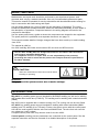
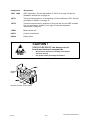
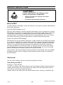
CAUTION!
Read and understand the instruction manual before
installing or operating.
WARNING!
Many parts of the power source are at mains voltage.
INTRODUCTION
Mig 4001i is a welding power source intended for MIG/MAG welding, as well as for welding
with powder filled cored wire (FCAW-S), TIG welding and for welding with coated electrodes
(MMA).
Mig 4001i can be supplied with or without cooling unit. The cooling unit can be retro fitted.
Arc 4001i is a welding power source intended for welding with coated electrodes (MMA
welding) and TIG welding (Live TIG-start). Further, the power source with the control panel
A24 can be used together with the wire feed unit MobileFeed. The wire feed unit uses the
arc voltage as control voltage.
A simpler control panel A22, may also be used for the Arc 4001i.
Control panels, welding process parameters are controlled via the control panel. See the
separate instruction and service manuals for a detailed description of the panels.

S0740 800 197/E100621/P74
- 5 -
ca42_00
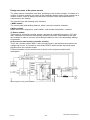
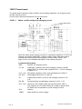
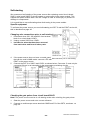
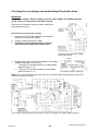
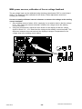
Design structure of the power source
The power source is transistor-controlled, operating on the inverter principle. It consists of a
number of function modules, as shown in the schematic diagram below. Each module has a
module number, which is always included as the first part of the name/identification of
components in the module.
The modules have the following main functions:
1 MMC module
The control panel and welding data unit, which control the machine functions.
2 Mains module
Mains interference suppressor, mains switch, control power transformer, contactor.
15 Power module
This module is a forward converter inverter, operating at a switching frequency of 27 kHz.
IGBT transistors are used as the switching elements. All power semiconductors are built
into modules in order to ensure a robust design suitable for use in the demanding welding
environment.
20 Processor board module (controller module)
This is the controller board, 20AP1, with a microprocessor, that monitors and controls the
voltage and current. It is served by relay board 20AP2, which handles input and output
signals to/from the controller board.
Further information on the modules can be found in the component and function
descriptions.
Block diagram of the power source

S0740 800 197/E100621/P74
- 6 -
ca42_00
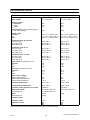
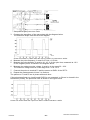
TECHNICAL DATA
Mig 4001i Arc 4001i
Mains voltage 400 V 10%, 3∼ 50/60 Hz 400 V 10%, 3∼ 50/60 Hz
Mains supply S
sc
min
2.2 MVA S
sc
min
2.2 MVA
Primary current
I
max
MIG/MAG
I
max
TIG
I
max
MMA
26 A
20 A
27 A
26 A
20 A
27 A
No-load power in energy-saving mode
6.5 min. after welding 60 W 60 W
Setting range
MIG/MAG
TIG
MMA
20 A / 15 V - 400 A / 34 V
4 A / 10 V - 400 A / 26 V
16 A / 21 V - 400 A / 36 V
20 A / 15 V - 400 A / 34 V
4 A / 10 V - 400 A / 26 V
16 A / 21 V - 400 A / 36 V
Permissible load at MIG/MAG
35% duty cycle
60 % duty cycle
100% duty cycle
400 A / 34 V
320 A / 30 V
250 A / 26.5 V
400 A / 34 V
320 A / 30 V
250 A / 26.5 V
Permissible load at TIG
35% duty cycle
60 % duty cycle
100% duty cycle
400 A / 26 V
320 A / 22.8 V
250 A / 20 V
400 A / 26 V
320 A / 22.8 V
250 A / 20 V
Permissible load at MMA
35% duty cycle
60 % duty cycle
100% duty cycle
400 A / 36 V
320 A / 32.8 V
250 A / 30 V
400 A / 36 V
320 A / 32.8 V
250 A / 30 V
Power factor at maximum curren
MIG/MAG
TIG
MMA
0.89
0.91
0.89
0.89
0.91
0.89
Efficiency at maximum curren
MIG/MAG
TIG
MMA
85 %
81 %
85 %
85 %
81 %
85 %
Open-circuit voltage
without VRD function
1)
VRD function deactivated
2)
VRD function activated
2)
91 V
58 V
< 35 V
91 V
58 V
< 35 V
Operating temperature -10 to +40° C -10 to +40° C
Transportation temperature -20 to +55° C -20 to +55° C
Continual sound pressure at no-load <70 db (A) <70 db (A)
Dimensions lxwxh
with cooling unit
652 x 249 x 423 mm
714 x 249 x 693 mm
652 x 249 x 423 mm
-
Weigt
with cooling unit
43.5 kg
63.5 kg
40 kg
Insulation class H H
Enclosure class IP 23 IP 23
Application class
1) Valid for power sources without VRD specification on the rating plate.

S0740 800 197/E100621/P74
- 7 -
ca42_00
2) Valid for power sources with VRD specification on the rating plate. The VRD function is explained in
the instruction manual for the control panel.
Mains supply, S
sc
min
Minimum short circuit power on the network in accordance with IEC 61000-3-12
Duty cycle
The duty cycle refers to the time as a percentage of a ten-minute period that you can weld at a cer
tain load without overloading. The duty cycle is valid for 40° C.
The duty cycle is valid for 40° C.
Enclosure class
The IP code indicates the enclosure class, i. e. the degree of protection against penetration by solid
objects or water. Equipment marked IP23 is designed for indoor and outdoor use.
Application class
The symbol indicates that the power source is designed for use in areas with increased
electrical hazard.
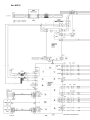
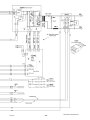
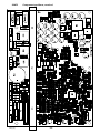
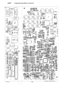
WIRING DIAGRAM
The power source consists of a number of function modules, which are described in the
component descriptions on the following pages. Wire numbers and component names in
the wiring diagrams show to which module each component belongs.
Wires/cables within modules are marked 100 - 6999.
Wires/cables between modules are marked 7000 - 7999.
Components outside modules - e.g. capacitors - are named such as C1 - C99, connection
(plug/socket) XS1 - XS99 (S = sleeve), XP1 - XP99 (P = pin) etc.
Circuit boards within each module have names such as 20AP1 - 20AP99.
20 = module association, 1-69
AP = circuit board
1 = individual identification number, 0-99
Transistors within particular modules have identification numbers such as 15Q1 -
15Q99.
15 = module association, 1-69
Q = transistor
1 = individual identification number, 0-99
Component description
Component Description
AP2 Interference suppressor board. See diagram on page 14.
C3 Capacitor, 100 nF 250 V.
XP.. Plug connectors. (Pin)
XS.. Socket connectors. (Sleeve)

S0740 800 197/E100621/P74
- 8 -
ca42_00
Component Description
XT.. Terminal blocks.
1 MMC module. Wire numbers 100-199. See description on page 14.
2 Mains module. Wire numbers 200-299.
2AP1 EMC suppressor board. See diagram on page 15.
2FU1 Fuse, 0.5 A slow blow (anti-surge).
2FU2 Fuse, 3.15 A slow blow (anti-surge).
2FU3 Fuse, 4 A slow blow (anti-surge).
2FU4 Fuse, 10 A slow blow (anti-surge).
2KM1 Main contactor. See 20AP2:3 on page 36.
2QF1 Mains switch. See 20AP2:3 on page 36.
2TC1 Auxiliary transformer.
3 Primary inductor module. Wire numbers 300-399.
3L1 Primary inductor.
5 Water cooling module. Wire numbers 500-599.
The power supply to the cooling water pump and fan is controlled by the
machine software. See the description of the 20AP2:5 on page 37.
7L1, 7L2 Ferrite rings, fitted to each end of cable 7200.
15 Power module. Wire numbers 1500-1699. See the schematic diagram
and description on page 16.
15AP1 Power board.
15AP2 Gate driver board.
15AP3 Current sensor. See the description of 20AP1:8 on page 28.
15BR1 Rectifier bridge. See the description of 15AP1:1 on page 17 and the
assembly instructions on page 49.
15D1, 15D2 Rectifier and freewheel diode modules. Each module consists of two
diodes.
15D1 rectifies the welding current. During the time interval between two
voltage pulses from transformer 15TM1, the freewheel diodes 15D2
maintain the welding current from inductor 15L3.
See page 49 for assembly instructions for the diode modules.
15EV1, 15EV2 Fans, 24 V DC. See the description of 20AP1:2 on page 24.
15L1, 15L2 2 + 2 ferrite rings. Reduce transient voltages produced when the diode
modules 15D1 and 15D2 turn off.
15L3 Inductor.

S0740 800 197/E100621/P74
- 9 -
ca42_00
Component Description
15Q1, 15Q2 IGBT transistors. See the description of 15AP1:2 on page 18 and the
installation instructions on page 49.
15ST1 Thermal overload cutout, in the winding of main transformer TM1. See the
description of 20AP1:4 on page 27.
15ST2 Thermal overload cutout, mounted on the heat sink for the IGBT modules.
See the description of 20AP1:4 on page 27 and the installation
instructions on page 49.
15TM1 Main transformer.
20AP1 Control circuit board.
20AP2 Relay board.
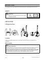
CAUTION !
STATIC ELECTRICITY can damage circuit
boards and electronic components.
Observe precautions for handling electrostatic-
sensitive devices.
Use proper static-proof bags and boxes.
ESD
Placement of the circuit boards

S0740 800 197/E100621/P74
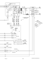
Arc 4001i
- 10 -
ca42_00

S0740 800 197/E100621/P74
- 11 -
ca42_00

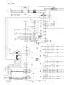
S0740 800 197/E100621/P74
Mig 4001i
- 12 -
ca42_00

S0740 800 197/E100621/P74
- 13 -
ca42_00

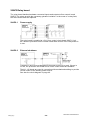
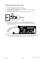
S0740 800 197/E100621/P74
MMC unit A22
MMC unit A24
- 14 -
ca42_01
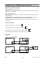
DESCRIPTION OF OPERATION
This description of operation describes the function of circuit boards and other components
in the equipment. It is divided into sections, numbered to correspond to the circuit board
numbers and divisions into function blocks.
AP2 Interference suppressor board
Component positions and circuit diagram for circuit board AP2
The circuit board removes interference signals.
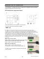
1 MMC unit
The MMC unit can either be fitted to the wire feed unit and/or the power source.
The MMC unit consists of an operator's control panel and a welding data board with a
welding data unit. In some applications the welding data unit is a part of the power source
control board, then there is no welding data board included in the MMC unit.
The power source, the wire feed unit and the welding data unit each have their own
microprocessor for control, with the welding data unit being the central unit in the system. In
addition to storing and issuing welding data, it also exercises overall control of the system
as a whole.
MMC units for the Arc 4001i
A22 is a MMC unit without welding data board. The welding
data unit is a part of the power source control board.
A24 is a MMC unit with welding data board.
MMC unit for the Mig 4001i
A24 is a MMC unit with welding data board.
The Mig 4001i can also be delivered without MMC unit.
The MMC units are described in separate instruction and
service manuals.

S0740 800 197/E100621/P74
- 15 -
ca42_02
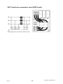
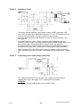
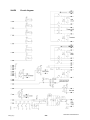
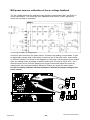
2AP1 Interference suppressor board (EMC board)
Circuit diagram and component positions, 2AP1

S0740 800 197/E100621/P74
- 16 -
ca42_15
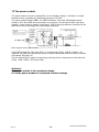
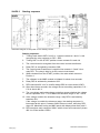
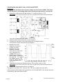
15 The power module
The power module converts 3-phase 400 V to the welding voltage. It consists of a single
forward inverter, operating at a switching frequency of 27 kHz.
The mains rectifier bridge 15BR1, the IGBT transistors 15Q1 and 15Q2 and the diode
modules 15D1 and 15D2 are all mounted on a heat sink. Circuit board 15AP1 links them
together. It also carries a smaller circuit board, 15AP2, which provides the functions for the
gate drivers and overvoltage and undervoltage protection.
Block diagram of the power module
If the IGBT transistors 15Q1 and 15Q2, or circuit boards 15AP1, 15AP2 or 20AP1, are
replaced, the gate pulse waveforms must be checked afterwards and the machine must be
soft-started. See page 50.
See the instructions on page 49 concerning mounting of the components on the heat sink
(15Q1, 15Q2, 15BR1, 15D1 and 15D2).
WARNING!
The power module is live at mains voltage.
0 V in the power module is connected to mains voltage.

S0740 800 197/E100621/P74
- 17 -
ca42_15
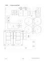
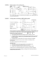
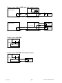
15AP1 Power board
The power board carries the mains rectifier, the smoothing capacitors, the charging circuit
and the switching circuit.
Circuit board connectors marked NC are n
ot connected.
15AP1:1 Mains rectifier bridge and charging circuit
When the mains power supply is turned on, smoothing capacitors C13-C16 are
charged via rectifier bridge BR2. Contactor 2KM1 closes after about twelve
seconds and connects the mains supply to rectifier bridge 15BR1. See
page 36 for a more detailed description of the starting sequence.
Component description:
BR2 Rectifier for charging current.
C1, C2 Capacitors, restricting the inrush charging current to rectifier
bridge BR2. The current while capacitors C13 - C16 are charging
is about 0.7 A.
C13 - C16 Smoothing capacitors, with a total capacitance of 1000 mF.
R5, R10 Discharging resistors for C1 and C2.
R1 Load-limiting resistor (10 W) for the charging current to C13 -
C16.
R8, R9 Potential divider and discharge resistors for C13 - C16.
R11 - R13 Varistors. Limit voltage peaks that exceeds about 1000 V.
The varistors do not conduct when the voltage is below 480 V
AC RMS, this corresponds to a peak voltage of 680 V.
R14 Varistor.
15BR1 Main rectifier for mains voltage.

S0740 800 197/E100621/P74
- 18 -
ca42_15
15AP1:2 Switching circuit
The power module switching components consist of IGBT transistors 15Q1
and 15Q2, operating at a switching frequency of 27 kHz. The transistors must
never be energised when the gate connections are removed.
The gate pulse waveforms and duration are vital for correct operation. See
also page 20.
If an IGBT transistor (15Q1, 15Q2) has failed, both transistors must be
replaced. Failure of either transistor always subjects rectifier bridge 15BR1 to a
high current surge, which substantially reduces its life. We therefore
recommend that the rectifier bridge should also be replaced if the transistors
have failed. See page 48 for instructions on checking the IGBT transistors.
Diode modules 15D1 and 15D2 each contain two diodes. Both they and the
IGBT transistors must be mounted in accordance with the instructions on page
49.
15AP1:3 Overvoltage and undervoltage protection
The voltage protection function monitors the voltage across smoothing
capacitors C13-C16. See page 21 for a description of operation.
CAUTION!
Do not mix up contacts B and D on circuit board 15AP2.

S0740 800 197/E100621/P74
- 19 -
ca42_15
15AP1 Component positions

S0740 800 197/E100621/P74
- 20 -
ca42_15
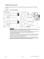
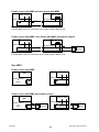
15AP2 Gate driver board
The gate driver board carries circuitry for gate driving and overvoltage and undervoltage
protection.
15AP2:1 Gate driver stages
WARNING!
Dangerous voltage - mains voltage. Never measure the gate signals when
the power source is connected to the mains supply.
The pulse frequency is 27 kHz, with a maximum pulse width of 39.0 - 40.8 % of
the cycle width. See page 50 for screen traces of waveforms and
measurement instructions.
Transformers TR1 and TR2 are gate driver transformers for galvanic isolation
of the drive circuits from controller board 20AP1. Fuses S1 and S2 protect the
gate driver circuit if the IGBT transistors fail.
Transistor module 15Q1 has a diode connected in series with its emitter: this
transistor has the identification 'GAR' on its case. Transistor 15Q2 has a diode
in series with its collector, and is identified by 'GAL' on its case.
Page is loading ...
Page is loading ...
Page is loading ...
Page is loading ...
Page is loading ...
Page is loading ...
Page is loading ...
Page is loading ...
Page is loading ...
Page is loading ...
Page is loading ...
Page is loading ...
Page is loading ...
Page is loading ...
Page is loading ...
Page is loading ...
Page is loading ...
Page is loading ...
Page is loading ...
Page is loading ...
Page is loading ...
Page is loading ...
Page is loading ...
Page is loading ...
Page is loading ...
Page is loading ...
Page is loading ...
Page is loading ...
Page is loading ...
Page is loading ...
Page is loading ...
Page is loading ...
Page is loading ...
Page is loading ...
Page is loading ...
Page is loading ...
Page is loading ...
Page is loading ...
Page is loading ...
Page is loading ...
Page is loading ...
Page is loading ...
Page is loading ...
Page is loading ...
Page is loading ...
Page is loading ...
Page is loading ...
Page is loading ...
Page is loading ...
Page is loading ...
Page is loading ...
Page is loading ...
Page is loading ...
Page is loading ...
-
 1
1
-
 2
2
-
 3
3
-
 4
4
-
 5
5
-
 6
6
-
 7
7
-
 8
8
-
 9
9
-
 10
10
-
 11
11
-
 12
12
-
 13
13
-
 14
14
-
 15
15
-
 16
16
-
 17
17
-
 18
18
-
 19
19
-
 20
20
-
 21
21
-
 22
22
-
 23
23
-
 24
24
-
 25
25
-
 26
26
-
 27
27
-
 28
28
-
 29
29
-
 30
30
-
 31
31
-
 32
32
-
 33
33
-
 34
34
-
 35
35
-
 36
36
-
 37
37
-
 38
38
-
 39
39
-
 40
40
-
 41
41
-
 42
42
-
 43
43
-
 44
44
-
 45
45
-
 46
46
-
 47
47
-
 48
48
-
 49
49
-
 50
50
-
 51
51
-
 52
52
-
 53
53
-
 54
54
-
 55
55
-
 56
56
-
 57
57
-
 58
58
-
 59
59
-
 60
60
-
 61
61
-
 62
62
-
 63
63
-
 64
64
-
 65
65
-
 66
66
-
 67
67
-
 68
68
-
 69
69
-
 70
70
-
 71
71
-
 72
72
-
 73
73
-
 74
74


ESAB Mig 4001i User manual
- Category
- Welding System
- Type
- User manual
- This manual is also suitable for
Ask a question and I''ll find the answer in the document
Finding information in a document is now easier with AI
Related papers
-
ESAB A22 User manual
-
ESAB Mig 4001i User manual
-
ESAB Tig 4000i User manual
-
ESAB IGBT Module Field Replacement Kit Troubleshooting instruction
-
-
-
-
-
ESAB AristoArc 400 User manual
-
ESAB Mig U5000i User manual
Other documents
-
Scotsman Printed Circuit Board Handling Precautions - 17-2307-01 Operating instructions
-
Cebora 180 Pulsed arc welding unit User manual
-
 PROGRESSIVE INDUSTRIES EMS-HW50C Operating instructions
-
 Cables Direct RB-249 Datasheet
-
AVT 1605 Two State Servo Controller Operating instructions
-
-
Sonel DB-1 User manual
-
-
Miller KC000000 Owner's manual
-

