Page is loading ...

Copyright © 2014 by Elenco
®
Electronics, Inc. All rights reserved. No part of this book shall be reproduced by 753134
any means; electronic, photocopying, or otherwise without written permission from the publisher.
Patents: 7,144,255; 7,273,377; & other patents pending
Project 66
SCM-165_Manual_061114.qxp_Layout 1 7/3/14 1:06 PM Page 1

-1-
1. Most circuit problems are due to incorrect
assembly, always double-check that your circuit
exactly matches the drawing for it.
2. Be sure that parts with positive/negative
markings are positioned as per the drawing.
3. Be sure that all connections are securely
snapped.
4. Try replacing the batteries.
5. If the light motor (M7) spins but the lights do not
turn on, make sure you installed it with the “+”
side oriented correctly.
If you suspect you have damaged parts, use the
Advanced Troubleshooting procedure on pages 13
and 14 to determine which ones need replacing.
ELENCO
®
is not responsible for parts damaged due
to incorrect wiring.
Basic Troubleshooting
Basic Troubleshooting 1
Parts List 2, 3
How to Use Snap Circuits
®
4
Airplane Assembly 5
Crawler Assembly 6, 7
About Your Snap Circuits
®
Parts 8 - 10
Introduction to Electricity 11
DOs and DON’Ts of Building Circuits 12
Advanced Troubleshooting 13, 14
Project Listings 15, 16
Projects 1 - 168 17 - 81
Notes 82
Other Snap Circuits
®
Projects 83
WARNING: SHOCK HAZARD - Never connect Snap
Circuits
®
to the electrical outlets in your home in any way!
Table of Contents
WARNING: Always check your wiring before
turning on a circuit. Never leave a circuit
unattended while the batteries are installed.
Never connect additional batteries or any
other power sources to your circuits.
Discard any cracked or broken parts.
Adult Supervision: Because children’s
abilities vary so much, even with age groups,
adults should exercise discretion as to
which experiments are suitable and safe (the
instructions should enable supervising
adults to establish the experiment’s
suitability for the child). Make sure your child
reads and follows all of the relevant
instructions and safety procedures, and
keeps them at hand for reference.
This product is intended for use by adults
and children who have attained sufficient
maturity to read and follow directions and
warnings.
Never modify your parts, as doing so may
disable important safety features in them,
and could put your child at risk of injury.
CAUTION: Persons who are extremely
sensitive to flashing lights and rapidly
changing colors or patterns should exercise
caution when playing with this toy.
Keep this booklet because it contains
important information.
WARNING FOR ALL PROJECTS WITH A SYMBOL -
Moving parts. Do not touch the motor or fan during operation. Eye protection is recommended.
!
!
!
WARNING: CHOKING HAZARD -
Small parts. Not for children under 3 years.
!
● Use only 1.5V AA type, alkaline batteries (not
included).
● Insert batteries with correct polarity.
● Non-rechargeable batteries should not be
recharged. Rechargeable batteries should
only be charged under adult supervision, and
should not be recharged while in the product.
● Do not mix old and new batteries.
● Do not connect batteries or battery holders in
parallel.
● Do not mix alkaline, standard (carbon-zinc),
or rechargeable (nickel-cadmium) batteries.
● Remove batteries when they are used up.
● Do not short circuit the battery terminals.
● Never throw batteries in a fire or attempt to
open its outer casing.
● Batteries are harmful if swallowed, so keep
away from small children.
Batteries:
!
Conforms to all
applicable U.S.
government
requirements.
SCM-165_Manual_061114.qxp_Layout 1 7/3/14 1:06 PM Page 2

-2-
Important: If any parts are missing or damaged, DO NOT RETURN TO RETAILER. Call toll-free (800) 533-2441 or e-mail us at:
Parts List (Colors and styles may vary) Symbols and Numbers (page 1)
Qty. ID Name Symbol Part # Qty. ID Name Symbol Part #
r 1
Base Grid
(11.0” x 7.7”)
6SCBG
r 1
100mF Capacitor 6SCC4
r 3
1-Snap Wire 6SC01
r 1
1mF Capacitor 6SCC7
r 6
2-Snap Wire 6SC02
r 1
Crawler Body 6SCCRAWB
r 3
3-Snap Wire 6SC03
r 1
Crawler Parts 6SCCRAWP
r 1
4-Snap Wire 6SC04
r 1
Color Light Emitting
Diode (LED)
6SCD8
r 1
5-Snap Wire 6SC05
r 1
Red/Yellow Bicolor Light
Emitting Diode (LED)
6SCD10
r 1
6-Snap Wire 6SC06
r 1
1.0” Gear 6SCGEAR1
r 1
Air Fountain 6SCAF
r 1
1.75” Gear 6SCGEAR2
r 1
Ball for Air Fountain 6SCAFB
r 1
2.55” Gear 6SCGEAR3
r 1
Spout for Air Fountain
6SCAFS
r 1
3.3” Gear 6SCGEAR4
r 2
Battery Holder - uses two (2)
1.5V type “AA” (not Included)
6SCB1
r 1
Geared Motor 6SCGM
r 1
Rubber Band 6SCBAND1
r 1
Jumper Wire (Black) 6SCJ1
r 1
“+” Shaped Bar 6SCBAR1
r 1
Jumper Wire (Red) 6SCJ2
You may order additional / replacement parts at our website: www.snapcircuits.net
5
4
3
2
1
GM
6
AF
C7
C4
B1
D8
D10
SCM-165_Manual_061114.qxp_Layout 1 7/3/14 1:06 PM Page 3

-3-
Important: If any parts are missing or damaged, DO NOT RETURN TO RETAILER. Call toll-free (800) 533-2441 or e-mail us at:
Parts List (Colors and styles may vary) Symbols and Numbers (page 2)
Qty. ID Name Symbol Part # Qty. ID Name Symbol Part #
r 1
Light Motor 6SCM7
r 2
Rubber Ring, 0.375” Dia.
6SCRUBRG
r 1
Mini Car 6SCMCAR
r 1
Slide Switch 6SCS1
r 1
Merry-Go-Round Base
6SCMGRB
r 1
Vibration Switch 6SCS4
r 1
Set of Disc Cutouts
(4 pcs. / set)
6SCMGRD
r 1
Switcher 6SCS6
r 1
Set of Cardboard
Figures (9 pcs. / set)
6SCMGRF
r 1
Tilt Switch 6SCS7
r 1
Airplane Parts
(must be punched out)
6SCPLANE
r 2
Screw PAW 2.6mm x
6mm
6SCSCREW1
r 1
Pivot Stand 6SCPSB
r 2
Screw PA 2.3mm x
8mm
6SCSCREW2
r 1
0.9” Pulley 6SCPULL1
r 1
Speaker 6SCSP2
r 1
1.3” Pulley 6SCPULL2
r 1
Alarm IC 6SCU2
r 1
2.1” Pulley 6SCPULL3
r 1
Motion Detector 6SCU7
r 1
NPN Transistor 6SCQ2
r 1
Blue Stand 626100
r 1
Adjustable Resistor 6SCRV2
You may order additional / replacement parts at our website: www.snapcircuits.net
U7
M7
Q2
RV2
U2
SP2
S7
S6
S4
S1
SCM-165_Manual_061114.qxp_Layout 1 7/3/14 1:07 PM Page 4

How to Use SnapCircuits
®
Snap Circuits
®
uses building blocks with snaps
to build the different electrical and electronic
circuits in the projects. Each block has a
function: there are switch blocks, light blocks,
battery blocks, different length wire blocks, etc.
These blocks are different colors and have
numbers on them so that you can easily
identify them. The blocks you will be using are
shown as color symbols with level numbers
next to them, allowing you to easily snap them
together to form a circuit.
For Example:
This is the switch block which is green and has
the marking on it. The part symbols in this
booklet may not exactly match the appearance
of the actual parts, but will clearly identify them.
This is a wire block which is blue and comes
in different wire lengths.
This one has the number , , , ,
or on it depending on the length of the wire
connection required.
There is also a 1-snap wire that is used as a
spacer or for interconnection between different
layers.
You need a power source to build each circuit.
This is labeled and requires two (2) 1.5V
“AA” batteries (not included).
A large clear plastic base grid is included with
this kit to help keep the circuit blocks properly
spaced. You will see evenly spaced posts that
the different blocks snap into. The base has
rows labeled A-G and columns labeled 1-10.
Next to each part in every circuit drawing is a
small number in black. This tells you which
level the component is placed at. Place all
parts on level 1 first, then all of the parts on
level 2, then all of the parts on level 3, etc.
Some circuits use the jumper wires to make
unusual connections. Just clip them to the
metal snaps or as indicated.
The set contains 9 pre-
punched cardboard
figures, which can be
inserted into slots in the
merry-go-round base.
The figures are supplied
as a single sheet; just
punch them out.
This set contains 4 pre-
punched cardboard discs.
These will be used to make
hypnotic patterns in project
47, with a strobe light in
project 48, and in other
projects. The discs are
supplied as a single sheet; just punch them out.
S1
2
3 4 5
6
B1
-4-
To remove a disc from the holder, flip the
holder over and poke the disc out with
your finger as shown.
SCM-165_Manual_061114.qxp_Layout 1 7/3/14 1:07 PM Page 5

5
9
9
9
8
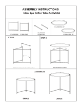
Airplane Assembly
3 3
3 3
1
2
4
4
6
7
-5-
Step 1
Step 2
Step 3
Note: The airplane is used in
project 27 and others, usually with
the light motor (M7) mounted on it.
SCM-165_Manual_061114.qxp_Layout 1 7/3/14 1:07 PM Page 6

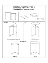
Crawler Assembly
-6-
Step 3 Step 4
Step 2
Flat side
Step 1
Note: The crawler is used in project 31 and
others, usually with the geared motor (GM)
mounted on it.
A
B
C
3
1
2
4
1
2 2
3
3
3
3
3
3
4
4
4
4
4
4
2
4
3
3
Note
direction
SCM-165_Manual_061114.qxp_Layout 1 7/3/14 1:07 PM Page 7

Crawler Assembly
Step 6
Step 7 Step 8
-7-
Step 5
IMPORTANT: Disassembling the
crawler base is not recommended.
The 1.75” gear used in step 1 is not
needed anywhere else. The geared
motor (GM) is removable, and is
used throughout the projects.
Note
direction
4 4
4
3
3
3
4
SCM-165_Manual_061114.qxp_Layout 1 7/3/14 1:07 PM Page 8

-8-
About Your Snap Circuits
®
Parts
(Part designs are subject to change without
notice).
BASE GRID
The blue snap wires
are wires used to
connect components.
They are used to
transport electricity and do
not affect circuit performance.
They come in different lengths to
allow orderly arrangement of connections
on the base grid.
The red and black
jumper wires make
flexible connections for
times when using the snap wires
would be difficult. They also are
used to make connections off the base grid.
Wires transport electricity just like pipes are used
to transport water. The colorful plastic coating
protects them and prevents electricity from
getting in or out.
BATTERY HOLDER
The base grid is a platform for mounting parts
and wires. It functions like the printed circuit
boards used in most electronic products, or like
how the walls are used for mounting the electrical
wiring in your home.
SNAP WIRES & JUMPER WIRES
The batteries (B1) produce an electrical voltage
using a chemical reaction. This “voltage” can be
thought of as electrical pressure, pushing
electricity through a circuit just like a pump
pushes water through pipes. This voltage is
much lower and much safer than that used in
your house wiring. Using more batteries
increases the “pressure”, therefore, more
electricity flows.
Battery Holder (B1)
The speaker (SP2)
converts electricity into
sound by making
mechanical vibrations.
These vibrations create
variations in air
pressure, which travel
across the room. You
“hear” sound when your
ears feel these air
pressure variations.
SPEAKER
Speaker (SP2)
SWITCHES
Switches connect (“ON”) or disconnect (“OFF”) the
wires in a circuit. When ON they have no effect on
circuit performance. Switches turn on electricity just
like a faucet turns on water from a pipe. Snap
Circuits
®
Motion includes several different switches:
The slide switch (S1) is a simple switch like most in
your home.
The switcher (S6) is a more complex switch used to
reverse the wires to a component or circuit. See
project 2 for an example of connections.
Switcher (S6)
One side of the vibration switch (S4) connects to a
spring, the other side connects to a wire through the
spring. When the spring is shaken, the spring
bounces to connect or disconnect the circuit.
Vibration Switch (S4)
Slide Switch (S1)
The tilt switch (S7) has a ball that can roll to make
connections between the center and one of the sides.
Tilt Switch (S7)
SCM-165_Manual_061114.qxp_Layout 1 7/3/14 1:07 PM Page 9

About Your Snap Circuits
®
Parts
RESISTORS
-9-
Adjustable Resistor (RV2)
The adjustable resistor (RV2) is a 10,000W
resistor but with a center tap that can be adjusted
between 200W and 10,000W.
Resistors “resist” the flow of electricity and are
used to control or limit the current in a circuit.
Snap Circuits
®
Motion has two resistors (
47W and
10,000W
) inside the pivot stand, and an
adjustable resistor. Materials like metal have very
low resistance (<1W), while materials like paper,
plastic, and air have near-infinite resistance.
Increasing circuit resistance reduces the flow of
electricity.
CAPACITORS
The 1mF and 100mF capacitors (C7 & C4) can
store electrical pressure (voltage) for periods of
time. This storage ability allows them to block
stable voltage signals and pass changing ones.
Capacitors are used for filtering and delay
circuits.
Pivot Stand
MOTOR MODULES
Geared Motor
The air fountain (AF) has a motor and fan
inside. The fan sucks air in from the side and
pushes it out the top. As the air comes out it
spreads out like a fountain of water and can
balance light round objects like the ball.
Reversing the voltage to the air fountain reduces
the power of the airflow due to the shape of the
fan.
Air Fountain
The light motor (M7) is a motor with an LED
circuit mounted on its shaft. A motor converts
electricity into mechanical motion, in the form of
a spinning shaft. In the light motor electricity is
transported through the motor shaft to power an
LED circuit, with LEDs mounted on the fan blade.
The motor spins in both directions, but the light
circuit only works in one direction.
How does electricity turn the shaft in the motor?
Electricity is closely related to magnetism, and
an electric current flowing in a wire has a
magnetic field similar to that of a very, very tiny
magnet. Inside the motor is three coils of wire
with many loops. If a large electric current flows
through the loops, the magnetic effects become
concentrated enough to move the coils. The
motor has a magnet inside, so as the electricity
moves the coils to align them with the permanent
magnet, the shaft spins.
Light Motor (M7)
Capacitors (C4 &C7)
The geared motor (GM) is a motor with a
gearbox attached. The gearbox makes the
attached “+” shaped shaft spin slower but with
more force than the shaft that is directly attached
to the motor.
SCM-165_Manual_061114.qxp_Layout 1 7/3/14 1:07 PM Page 10

-10-
About Your Snap Circuits
®
Parts
ELECTRONICMODULES
IN1
(–)
IN2
IN3
OUT
Connections:
IN1, IN2, IN3 - control inputs
(–) - power return to batteries
OUT - output connection
Connect control inputs to (+) power to make five
alarm sounds, see project 39 for an example of
proper connections.
The alarm IC (U2) contains a specialized sound-
generation integrated circuit (IC) and other
supporting components (resistors, capacitors,
and transistors) that are always needed with it.
A schematic for it is available at
www.snapcircuits.net/faq.
The motion detector (U7) contains an infrared
detector, amplifier-filter circuit, and timing circuit.
A schematic for it is available at
www.snapcircuits.net/faq.
All objects (including people and animals)
produce infrared radiation due to the heat in
them. Infrared radiation is similar to visible light
but has a longer wavelength that our eyes cannot
detect. The lens on top of the motion detector
module filters and focuses the radiation, it is most
sensitive to the radiation produced by our bodies.
Inside the motion detector module is an infrared
detector with pyroelectric crystals, which create
a tiny voltage when exposed to infrared radiation.
A circuit amplifies and filters this voltage, but only
responds to changes in the radiation level - so is
only triggered by moving objects (motion). When
motion is detected a timing circuit is used to
control other snap circuits devices for a few
seconds, such as an alarm.
(+)
OUT
(–)
Connections:
(+) - regulated power from batteries
(–) - power return to batteries
OUT - output connection
Lens
LEDs (D8&D10)
TRANSISTORS
The NPN transistor (Q2) uses a small electric
current to control a large current, and is used in
switching, amplifier, and buffering applications.
Transistors are easy to miniaturize, and are the
main building blocks of integrated circuits
including the microprocessor and memory
circuits in computers.
LEDs
The color LED(D8) and red/yellow bicolor
LED (D10) are light emitting diodes, and may be
thought of as a special one-way light bulbs. In the
“forward” direction, (indicated by the “arrow” in
the symbol) electricity flows if the voltage
exceeds a turn-on threshold (about 1.5V for red,
slightly higher for yellow, about 2.0V for green,
and about 3.0V for blue); brightness then
increases. The color LED contains red, green,
and blue LEDs, with a micro-circuit controlling
then. The red/yellow bicolor LED contains red &
yellow LEDs in connected in opposite directions.
A high current will burn out an LED, so the
current must be limited by other components in
the circuit (though your Snap Circuits
®
LEDs
have internal resistors to protect against incorrect
wiring). LEDs block electricity in the “reverse”
direction.
NPNTransistor (Q2)
SCM-165_Manual_061114.qxp_Layout 1 7/3/14 1:07 PM Page 11

-11-
Introduction to Electricity
What is electricity? Nobody really knows. We only know how to produce it,
understand its properties, and how to control it. Electricity is the movement of sub-
atomic charged particles (called electrons) through a material due to electrical
pressure across the material, such as from a battery.
Power sources, such as batteries, push electricity through a circuit, like a pump
pushes water through pipes. Wires carry electricity, like pipes carry water. Devices
like LEDs, motors, and speakers use the energy in electricity to do things. Switches
and transistors control the flow of electricity like valves and faucets control water.
Resistors limit the flow of electricity.
The electrical pressure exerted by a battery or other power source is called
voltage and is measured in volts (V). Notice the “+” and “–” signs on the battery;
these indicate which direction the battery will “pump” the electricity.
The electric current is a measure of how fast electricity is flowing in a wire, just
as the water current describes how fast water is flowing in a pipe. It is expressed
in amperes (A) or milliamps (mA, 1/1000 of an ampere).
The “power” of electricity is a measure of how fast energy is moving through a
wire. It is a combination of the voltage and current (Power = Voltage x Current). It
is expressed in watts (W).
The resistance of a component or circuit represents how much it resists the
electrical pressure (voltage) and limits the flow of electric current. The relationship
is Voltage = Current x Resistance. When the resistance increases, less current
flows. Resistance is measured in ohms (W), or kilo ohms (kW, 1000 ohms).
Nearly all of the electricity used in our world is produced at enormous generators
driven by steam or water pressure. Wires are used to efficiently transport this
energy to homes and businesses where it is used. Motors convert the electricity
back into mechanical form to drive machinery and appliances. The most important
aspect of electricity in our society is that it allows energy to be easily transported
over distances.
Note that “distances” includes not just large distances but also tiny distances. Try
to imagine a plumbing structure of the same complexity as the circuitry inside a
portable radio - it would have to be large because we can’t make water pipes so
small. Electricity allows complex designs to be made very small.
There are two ways of arranging parts in a circuit, in series or
in parallel. Here are examples:
Placing components in series increases the resistance; highest
value dominates. Placing components in parallel decreases the
resistance; lowest value dominates.
The parts within these series and parallel sub-circuits may be
arranged in different ways without changing what the circuit
does. Large circuits are made of combinations of smaller series
and parallel circuits.
Series Circuit
Parallel Circuit
SCM-165_Manual_061114.qxp_Layout 1 7/3/14 1:07 PM Page 12

-12-
DOs and DON’Ts of Building Circuits
After building the circuits given in this booklet, you may wish to experiment on your
own. Use the projects in this booklet as a guide, as many important design concepts
are introduced throughout them. Every circuit will include a power source (the
batteries), a resistance (which might be a resistor, capacitor, motor, integrated circuit,
etc.), and wiring paths between them and back. You must be careful not to create
“short circuits” (very low-resistance paths across the batteries, see examples at right)
as this will damage components
and/or quickly drain your batteries. Only connect the
alarm IC (U2) and motion detector (U7) using configurations given in the projects,
incorrectly doing so may damage them. ELENCO
®
is not responsible for parts
damaged due to incorrect wiring.
Here are some important guidelines:
ALWAYS USE EYE PROTECTION WHEN EXPERIMENTING ON YOUR OWN.
ALWAYS include at least one component that will limit the current through a circuit,
such as the speaker, capacitors, ICs (which must be connected properly),
light or geared motors, air fountain, or resistors.
ALWAYS use LEDs, transistors, and switches in conjunction with other components
that will limit the current through them. Failure to do so will create a short
circuit and/or damage those parts.
ALWAYS connect capacitors so that the “+” side gets the higher voltage.
ALWAYS disconnect your batteries immediately and check your wiring if something
appears to be getting hot.
ALWAYS check your wiring before turning on a circuit.
ALWAYS connect the alarm IC (U2) and motion detector (U7) using configurations
given in the projects or as per the connection description on page 10.
NEVER connect to an electrical outlet in your home in any way.
NEVER leave a circuit unattended when it is turned on.
NEVER touch the light motor when it is spinning.
For all of the projects given in this book, the parts may be arranged in different ways without
changing the circuit. For example, the order of parts connected in series or in parallel does
not matter — what matters is how combinations of these sub-circuits are arranged together.
Placing a 3-snap wire directly
across the batteries is a
SHORT CIRCUIT.
This is also a
SHORT CIRCUIT.
When the slide switch (S1) is turned on, this large circuit has a SHORT
CIRCUIT path (as shown by the arrows). The short circuit prevents any
other portions of the circuit from ever working.
Examples of SHORT CIRCUITS - NEVER DO THESE!!!
You are encouraged to tell us about new programs and circuits you
create. If they are unique, we will post them with your name and state
on our website at:
www.snapcircuits.net/learning_center/kids_creation
Send your suggestions to ELENCO
®
ELENCO
®
provides a circuit designer so that you can make your own
Snap Circuits
®
drawings. This Microsoft
®
Word document can be
downloaded from:
www.snapcircuits.net/learning_center/kids_creation
or through the www.snapcircuits.net website.
WARNING: SHOCK HAZARD - Never connect Snap Circuits
®
to the electrical outlets in your home in any way!
Warning to Snap Circuits
®
owners: Do not connect
additional voltage sources from other sets, or you
may damage your parts. Contact ELENCO
®
if you
have questions or need guidance.
!
NEVER
DO!
!
!
NEVER
DO!
!
NEVER
DO!
!
NEVER
DO!
!
SCM-165_Manual_061114.qxp_Layout 1 7/3/14 1:07 PM Page 13

-13-
Advanced Troubleshooting
(Adult supervision recommended)
ELENCO
®
is not responsible for parts
damaged due to incorrect wiring.
If you suspect you have damaged parts, you
can follow this procedure to systematically
determine which ones need replacing:
(Note: Some of these tests connect an LEDdirectly
across the batteries without another component to
limit the current. Normally this might damage the
LED, however SnapCircuits
®
LEDs have internal
resistors added to protect them from incorrect
wiring, and will not be damaged.)
1. Color LED(D8), red/yellow bicolor LED
(D10), speaker (SP2), geared motor (GM),
and battery holder(B1):
● Place batteries in holder.
● Place the color LED directly across the
battery holder (LED + to battery +), it
should light and be changing colors.
● Place the red/yellow bicolor LED directly
across the battery holder, in both
orientations. It should light red when the
red side is to battery +, and yellow when
the yellow side is to battery +.
● “Tap” the speaker across the battery
holder contacts, you should hear static as
it touches.
● Place the geared motor directly across the
battery holder; its shaft should spin.
● If none of the above work, then replace
your batteries and repeat. If still bad, then
the battery holder is damaged. Test both
battery holders.
2. Red & black jumper
wires: Use this mini-
circuit to test each
jumper wire, the LED
should light.
3. Snap wires: Use this mini-circuit to test
each of the snap wires, one at a time. The
LED should light.
4. Slide switch (S1) and vibration switch
(S4): Use this mini-circuit; if the LED doesn’t
light then the slide switch is bad. Replace
the slide switch with the vibration switch;
tapping it should light the LED, or the
vibration switch is bad.
5. Light motor (M7): Build project 3. The light
motor should spin and lights in the fan blade
should make a colorful, changing pattern.
Be sure you orient the light motor as per the
drawing.
6. Air fountain (AF): Build project 6, and be
sure you have good batteries. Air blown out
of the top of the air fountain should make the
ball spin around and/or rise into the air.
7. Pivot stand resistors: The pivot stand has
resistors mounted inside; they can be tested
using the mini-circuit shown here. The
red/yellow LED (D10) should be bright and
the color LED (D8) should be very dim,
otherwise the pivot stand is damaged.
8. Adjustable resistor (RV2): Build project
133. Move the resistor control lever to both
sides. When set to each side, one LED
should be bright and the other dim;
otherwise RV2 is bad.
9. NPN transistor (Q2): Build the mini-circuit
shown here. The color LED (D8) should only
be on if the slide switch (S1) is on. If
otherwise, then Q2 is damaged.
10.
Tilt switch (S7): Build this mini-circuit and
tilt it in different directions. D10 should be on
at some tilt angles, D8 should be on at other
tilt angles, and sometimes both lights are off.
SCM-165_Manual_061114.qxp_Layout 1 7/3/14 1:07 PM Page 14

Advanced Troubleshooting
(Adult supervision recommended)
11. Alarm IC(U2): Build project 158, and the
variants for it. Each arrangement should
produce a siren sound, or U2 is broken.
12. Motion Detector(U7): Build project 18.
The LED (D8) should light for a few
seconds on power-up and then whenever
the circuit detects motion.
13. Switcher (S6): Build this mini-circuit. The
LED (D10) should be red when S6 is in the
top position, off when S6 is in the middle
position, and yellow when S6 is in the
bottom position; otherwise S6 is broken.
14.
1mF (C7) and 100mF (C4) capacitors:
Build project 139. Touch C4 or C7 across
points A & B, then across points C & D; the
LED (D10) should flash (brightly for C4 and
dimly for C7) or the capacitor is broken.
ELENCO
®
150 Carpenter Avenue
Wheeling, IL 60090 U.S.A.
Phone: (847) 541-3800
Fax: (847) 520-0085
e-mail: [email protected]
Website: www.elenco.com
You may order additional / replacement
parts at: www.snapcircuits.net
-14-
SCM-165_Manual_061114.qxp_Layout 1 7/3/14 1:07 PM Page 15

-15-
Project # Description Page #
1 Color Light 17
2 Reversible Light 17
3 Light Show 18
4 Dim Light Show 18
5 Vibration, Tilt, & Motion Detector 18
6 Dancing Ball 19
7 High Power Dancing Ball 19
8 Human Height Control 19
9 Double Dancer 19
10 Low Double Dancer 19
11 Vibration Light 20
12 Vibration Alarm 20
13 Tilt Sensor 20
14 Super Motion Detector 21
15 Short Spin Lights & Sound 21
16
Louder Short Spin Lights & Sound
21
17 Motion Detector Light 22
18 Low Power Motion Detector 22
19 Motion Detector Alarms 23
20
Merry-Go-Round Motion Detector
23
21 Mini Car 24
22 Mini Car with Control Light 24
23 High Speed Car 24
24 Mini Car with On-Board Control 25
25 Mini Car with Light 25
26 Mini Car with Motion Light 25
27 It’s a Plane! 26
28 Low Power Plane 26
Project #
Description Page #
29 Idling Plane 26
30 Light Plane 26
31 Crawler 27
32 Crawler with Control Light 27
33 High Speed Crawler 27
34 Crawler with On-Board Control 28
35 Crawler with Control Light 28
36 Crawler with Motion Light 28
37 Tilt Motion 29
38 Tilt Alarm 29
39 Alarm Sounds & Lights 30
40 Softer Alarms 30
41 Funky Colors Alarms 30
42 Lighthouse 31
43 Merry-Go-Round 31
44 Fast Merry-Go-Round 31
45
Merry-Go-Round with Music & Light
32
46
Fast Merry-Go-Round with Music & Light
32
47 Hypnotic Discs 33
48 Strobe Light with Music 33
49 Slow Merry-Go-Round 34
50 Merry-Go-Round with Lights 34
51 Fun with Gears 35
52 Higher Gear Ratio 35
53 Spin Draw 35
54 Strobe Light 36
55 Make Your Own Patterns 37
56 Fun with Pulleys 37
Project #
Description Page #
57 Secure Pulley 38
58 More Pulleys 38
59 Trip-Wire Lights 38
60 Triple Lights Motion 39
61 Double Lights Motion 39
62 Big Circuit 40
63 Vib Off 40
64 Audio Triple Detector 41
65 Vibration Plane 41
66 Too Much at Once? 42
67 Not Too Much at Once 43
68 Adjustable Motor & More 44
69 Adjustable Dancing Ball 44
70 Color Brightness Adjuster 45
71
Red or Yellow Brightness Adjuster
45
72 Yellow Brightness Adjuster 45
73 Double Brightness Adjuster 45
74
Two-Way Double Brightness Adjuster
46
75
Parallel Double Brightness Adjuster
46
76 Dim Double Brightness Adjuster 46
77 Secret Resistors 47
78
Adjustable Alarm Sounds & Light
47
79
Stable Adjustable Alarm Sounds & Light
47
80 Adjustable Volume Alarms 47
81 Double Red Siren 48
82 Double Lights Siren 48
83 Super Vibration Light 49
84 Fast Vibration Light 49
Project Listings
SCM-165_Manual_061114.qxp_Layout 1 7/3/14 1:07 PM Page 16

-16-
Project # Description Page #
85 Vibration Alarms & Lights 49
86 Shaky Alarms & Lights 49
87 Reversible Merry-Go-Round 50
88 Two-Way Circuit 50
89 Low Power Two-Way Circuit 50
90 Slow Off Tilt Alarm 51
91 Slow Off Tilt Light 51
92 Switcher Fun 51
93 Adjustable Slow Off Tilt Light 52
94 Color Slow Off Tilt Light 52
95 Very Slow Off Tilt Light 52
96 Bright Slow Off Tilt Light 52
97
Adjustable Slow Off Vibration Light
53
98 Color Slow Off Vibration Light 53
99 Very Slow Off Vibration Light 53
100 Bright Slow Off Vibration Light 53
101 Slow Off Tilt Lights 54
102 Very Slow Off Tilt Lights 54
103 Slow Off Vibration Lights 54
104 Very Slow Off Vibration Lights 54
105 Tilted Motion Detector 55
106 Tilt Off 55
107 Electricity In, Electricity Out 56
108 Little Electricity In/Out 56
109 Mini Rechargeable Battery 56
110 Mini Rechargeable Batteries 57
111 Left Right Bright Lights 57
112 Charge & Discharge 58
Project #
Description Page #
113 Super Charge & Discharge 58
114 Mini Charge & Discharge 58
115 Light Start 59
116 Double Motion 59
117 Triple Motion 60
118 Slow Triple Motion 60
119 Dominator 60
120 Lots at Once 61
121 Electrical Circle 61
122 Generator 62
123 Leverage 62
124 Generator Load 62
125 Water Alarm 63
126 Human Alarm 63
127 Draw an Alarm 63
128 Human & Water Light 64
129 Conduction Detector 64
130 Trip-Wire Alarm 64
131 Current Limiters 65
132 Current Limiters in Parallel 65
133 Current Director 66
134 Reversible Current Director 67
135 Lazy Fan 68
136 Lazy Merry-Go-Round 68
137 Lazy Lights 68
138 Very Lazy Lights 68
139
Electricity You Can Walk Away With
69
140
Electricity You Can Walk Away With (II)
69
Project #
Description Page #
141 Short Burst Machine Gun 70
142 Short Burst Sound & Lights 70
143 Short-On Light 70
144 Finger Touch Light 71
145 Slow Off Light 71
146 3-Position Switch 71
147 One Way Electricity 72
148 Tilt Sound & Light 72
149 Inflator 73
150 Transistor 73
151 Slow Light 74
152 Wiggler 74
153 Blinker Beeper 75
154 Blinker Blinker 75
155 Blinker Control 75
156 Red Lights First 76
157 Red Just Before Yellow 76
158 Loud Sirens 77
159 Adjustable Volume Sirens 77
160 Capacitors in Series 78
161 Capacitors in Parallel 78
162 Adjustable Low Speed Fan 79
163 Adjustable Light Motor 79
164 Transistor Control 80
165 Reversible Motor 80
166 Slow Reversible Motor 80
167 Orange Light 81
168 Light, Sound, & Flight 81
Project Listings
SCM-165_Manual_061114.qxp_Layout 1 7/3/14 1:07 PM Page 17

-17-
Project 1 Color Light
+
Project 2 Reversible Light
+
Placement Level Numbers
Snappy says the color LED actually contains
separate red, green, and blue lights, with a
micro-circuit controlling them.
The pivot stand is used here because it has
internal resistors that limit the flow of electricity,
and help protect the color LED from damage.
Snap Circuits
®
uses electronic blocks
that snap onto a clear plastic grid to
build different circuits. These blocks
have different colors and numbers on
them so that you can easily identify
them.
Build the circuit shown on the left by
placing all the parts with a black 1 next
to them on the board first. Then,
assemble parts marked with a 2. Install
two (2) “AA” batteries (not included)
into each of the battery holders (B1) if
you have not done so already.
Turn on the slide switch (S1), and
enjoy the light show from the color LED
(D8). For best effects, dim the room
lights.
Try replacing the color LED with the
red/yellow bicolor LED (D10), orienting
it in either direction.
Build the circuit as shown, turn on the slide
switch (S1), and then set the switcher (S6)
at each of its 3 positions. The red/yellow
bicolor LED (D10) should be yellow at the
top S6 position, off at the middle position,
and red at the bottom S6 position. For best
effects, dim the room lights.
Try replacing the red/yellow bicolor LED
with the color LED (D8, “+” on left). The
color LED isn’t bidirectional, so it only
works at the top S6 position.
LEDs are light emitting diodes, which
are like little light bulbs that only work
in one direction. The red/yellow
bicolor LED is actually a red LED and
a yellow LED, connected in opposite
directions inside the same part.
SCM-165_Manual_061114.qxp_Layout 1 7/3/14 1:07 PM Page 18

Snap Circuits
®
uses electronic blocks that snap onto a clear
plastic grid to build different circuits. These blocks have different
colors and numbers on them so that you can easily identify them.
Build the circuit shown on the left by placing all the parts with a
black 1 next to them on the board first. Then, assemble parts
marked with a 2. Install two (2) “AA” batteries (not included) into
each of the battery holders (B1) if you have not done so already.
Turn on the slide switch (S1) and watch the light show! For best
effects, dim the room lights.
Never touch the fan while it is spinning.
Project 3 Light Show
!
WARNING: Moving parts. Do not
touch the fan during operation.
+
Build the circuit and turn on the slide switch (S1). The color LED (D8)
lights for a few seconds on start-up, and then whenever the circuit
detects motion, feels vibration, or is tilted in some directions.
Project 5 Vibration, Tilt, &
Motion Detector
Project 4
Dim Light
Show
Use the preceding circuit, but
replace one of the battery holders
(B1) with a 3-snap wire. The circuit
works the same but is much
dimmer, giving some interesting
effects. For best effects, view in a
dimly lit room.
-18-
Placement Level Numbers
The fan on the light motor has
several LEDs, similar to the
ones in the D8 & D10 LEDs.
Electricity is transported
through the motor shaft to
power the LEDs.
SCM-165_Manual_061114.qxp_Layout 1 7/3/14 1:07 PM Page 19

Build the circuit as shown,
place the spout on the air
fountain (AF), turn on the slide
switch (S1), then place the
ball directly in the blowing air
above the air fountain. The
blowing air should balance
the ball, so it floats in the air
and “dances”. Occasionally
the ball may become unstable
and fall out; just place it back
into the air flow.
If desired, you may draw lines
or patterns on the ball. New
alkaline batteries are
recommended for this project.
Project 6
Dancing Ball
Project 7
High Power Dancing Ball
Use the preceding circuit, but replace the 3-snap wire with a second
battery holder (B1). The circuit works the same but the blowing air flow
is stronger, making the ball float higher but also making it unstable. As
a result, the ball may fall out quickly.
Try replacing the ball with other small, light balls in your home and see
which ones float in the airflow.
Build this circuit, turn on the slide switch (S1), set the
switcher (S6) to either the top or bottom position, and
place the ball in the air flow above the spout on the air
fountain (AF). See how long the ball floats in the air
for each S6 setting.
The top S6 setting has stronger air flow, but it may be
too strong, causing the ball to become unstable and
fall out. The bottom S6 setting makes the air flow a
little weaker, so the ball may be more stable and float
in the air better.
Try replacing the ball with other small, light balls in
your home and see which ones float in the airflow.
Project 9 Double Dancer
Use the preceding circuit, but
replace one of the battery
holders with a 3-snap wire. The
circuit works the same but the
blowing air flow is weaker. The
ball may wiggle around without
rising into the air.
The air is being blown by a fan blade inside the
air fountain. The switcher (S6) reverses the
direction that the fan spins, but the shape of the
fan makes the air flow stronger in one direction.
Use the preceding circuit, but place your fingers or thumb in front of the
air intake on the side of the air fountain, to partially block it. You can
make the ball float lower in the air by restricting the airflow. This may
make the ball be more stable and stay in the air longer.
-19-
Place the spout
on top of the air
fountain and the
ball in the air flow.
Project 8
Human Height Control
Project 10
Low Double
Dancer
Spout
SCM-165_Manual_061114.qxp_Layout 1 7/3/14 1:07 PM Page 20
/