Page is loading ...

1M23N32604
I
NSTRUCTION
M
ANUAL

2
Thank you for purchasing a Futaba 7PX-2.4GHz system.
Before use, read this manual carefully in order to use it safely.
After reading this manual, store it in a safe place.
IN NORTH AMERICA
Please feel free to contact the Futaba Service Center for assistance with operation and programming. Please
be sure to regularly visit the 7PX Frequently Asked Questions web site at KWWSVwww.futabaXVDFRP This
page includes extensive programming, use, set up and safety information on the 7PX radio system and is
updated
UHJXODUO\$Q\WHFKQLFDOXSGDWHVRU¿UPZDUHXSGDWHVDQG86 PDQXDO FRUUHFWLRQV ZLOOEHDYDLODEOHRQWKLV
ZHESDJH,I\RXGRQRW¿QGWKHDQVZHUVWR\RXUTXHVWLRQVWKHUHSOHDVHVHHWKHHQGRIRXU)$4DUHDIRULQ-
formation on contacting us via e-mail for the most rapid and convenient response.
Don’t you have Internet access? Internet access is available at no charge at most public libraries, schools,
and
RWKHUSXEOLFUHVRXUFHV:H¿QGLQWHUQHWVXSSRUWWREHDIDEXORXVUHIHUHQFHIRUPDQ\PRGHOHUVDVLWHPVFDQEH
printed and saved for future reference, and can be accessed at any hour of the day, night, weekend or holiday.
If you do not wish to access the internet for information, however, don’t worry. Our support teams are avail-
able Monday through Friday 8-5 Central time to assist you.
$SSOLFDWLRQ([SRUWDQG0RGL¿FDWLRQ
1. This product may be used for models only. It is not intended for use in any application other than the con-
trol of models for hobby and recreational purposes.
2. Exportation precautions:
(a) When this product is exported from the country of manufacture, its use is to be approved by the laws gov-
erning the country of destination for devices that emit radio frequencies. If this product is then re-exported
to other countries, it may be subject to restrictions on such export. Prior approval of the appropriate govern-
ment authorities may be required. If you have purchased this product from an exporter outside your country,
and not the authorized Futaba distributor in your country, please contact the seller immediately to determine
if such export regulations have been met.
E8VHRIWKLVSURGXFWZLWKRWKHUWKDQPRGHOVPD\EHUHVWULFWHGE\([SRUWDQG7UDGH&RQWURO5HJXODWLRQV
and an application for export approval must be submitted.
0RGL¿FDWLRQDGMXVWPHQWDQGUHSODFHPHQWRISDUWV)XWDEDLVQRWUHVSRQVLEOHIRUXQDXWKRUL]HGPRGL¿FD-
tion, adjustment, and replacement of parts on this product. Any such changes may void the warranty.
OUTSIDE NORTH AMERICA
Please contact the Futaba importer in your region of the world to assist you with any questions, problems or
service needs. Please recognize that all information in this manual, and all support availability, is based upon
the systems sold in North America only. Products purchased elsewhere may vary. Always contact your re-
gion’s support center for assistance.
FOR SERVICE ONLY:
)87$%$&RUSRUDWLRQRI$PHULFD
:DOO7ULDQD+Z\+XQWVYLOOH$/86$
3KRQH)$;
KWWSVZZZIXWDEDXVDFRP
(PDLOVHUYLFH#IXWDED86$FRP

3
Compliance Information Statement (for U.S.A.)
7KLVGHYLFHFRPSOLHVZLWKSDUWRIWKH)&&5XOHV2SHUDWLRQLVVXEMHFWWRWKHIROORZLQJWZRFRQGLWLRQV
(1) This device may not cause harmful interference, and (2) This device must accept any interference re-
ceived, including interference that may cause undesired operation.
5)5DGLDWLRQ([SRVXUH6WDWHPHQW)RU73;
This equipment complies with FCC radiation exposure limits set forth for an uncontrolled environment.
This transmitter must not be co-located or operating in conjunction with any other antenna or transmitter.
5)5DGLDWLRQ([SRVXUH6WDWHPHQW)RU56%6
This equipment complies with FCC radiation exposure limits set forth for an uncontrolled environment. This
equipment should be installed and operated with minimum distance 20cm between the radiator & your body.
The responsible party for the compliance of this device is:
)87$%$&RUSRUDWLRQRI$PHULFD
:DOO7ULDQD+Z\+XQWVYLOOH$/86$
3KRQH)$;
KWWSVZZZIXWDEDXVDFRP
(PDLOVHUYLFH#IXWDED86$FRP
CAUTION:
To assure continued FCC compliance:
$Q\FKDQJHVRUPRGL¿FDWLRQVQRWH[SUHVVO\DSSURYHGE\WKHJUDQWHHRIWKLVGHYLFHFRXOGYRLGWKHXVHU¶VDX-
thority to operate the equipment.
Declaration of Conformity (for EU)
Hereby, Futaba Corporation declares that the radio equipment type is in compliance with Directive 2014/53/
(8
7KHIXOOWH[WRIWKH(8GHFODUDWLRQRIFRQIRUPLW\LVDYDLODEOHDWWKHIROORZLQJLQWHUQHWDGGUHVV
http://www.rc.futaba.co.jp/english/dl/declarations.html
Battery Recycling (for U.S.A.)
7KH5%5&
™
SEAL on the (easily removable) nickel-cadmium battery and nickel-metal-
hydride battery contained in Futaba products indicates that Futaba Corporation is voluntarily
participating in an industry program to collect and recycle these batteries at the end of their
XVHIXOOLYHVZKHQWDNHQRXWRIVHUYLFHZLWKLQWKH8QLWHG6WDWHV7KH5%5&
™
program pro-
vides a convenient alternative to placing used nickel-cadmium batteries and nickel-metal-
hydride batteries into the trash or municipal waste system, which is illegal in some areas.
You may contact your local recycling center for information on where to return the spent battery. Please call
%$77(5< IRU LQIRUPDWLRQ RQ 1L&G1L0+ EDWWHU\ UHF\FOLQJ LQ \RXU DUHD )XWDED &RUSRUDWLRQV
involvement in this program is part of its commitment to protecting our environment and conserving natural
resources.
NOTE: Our instruction manuals encourage our customers to return spent batteries to a local recycling center
in order to keep a healthy environment.
5%5&
™
LVDWUDGHPDUNRIWKH5HFKDUJHDEOH%DWWHU\5HF\FOLQJ&RUSRUDWLRQ

4
Table Of Contents
For Your Safety As Well As That Of Others .........................8
Explanation Of Symbols ...............................................................8
Receiver Mode Precautions .........................................................8
Operation Precautions ..................................................................9
NiMH/NiCd/LiFe Battery Handling Precautions ........................10
Storage And Disposal Precautions ...........................................10
Other Precautions .......................................................................11
Installation ..........................................................................32
Receiver And Servo Connections .............................................32
Installation Safety Precautions ..................................................33
Before Using ......................................................................12
Features ......................................................................................12
Set Contents ...............................................................................14
Transmitter T7PX .........................................................................15
Nomenclature ........................................................................... 15
Battery Replacement Method...................................................16
Low Battery Alarm ....................................................................16
When Using The Optional Battery ............................................17
When Charging For The Optional Battery ................................18
Power & Display Switch ............................................................19
Display When Power Switch Is Turned On ...............................20
Power Off Forgotten Alarm & Auto Power Off ..........................20
Trim/Dial Lock ...........................................................................20
Steering Wheel And Throttle Trigger Operation ........................21
Digital Trim Operation ...............................................................21
Mechanical ATL Adjustment .....................................................22
Wheel & Trigger Tension Adjustment ........................................22
Trigger Slide Adjustment & Remove The High Point Spring .....23
Trigger brake lever replacement ...............................................23
Changing Wheel Position And Modifying For Left-hand Use ..24
Exchange procedure to wheel adaptor 32 deg ........................24
Installing the accessory APA steering wheel offset adapter .....24
Modifying for left-hand use .......................................................27
Using the optional angle spacer ................................................29
Non-telemetry LED (telemetry OFF sign) ..................................29
Handling the antenna and card slot and receiver ....................30
About The Transmitter Antenna ................................................30
Receiver Terminology ...............................................................30
Receiver Installation .................................................................30
Handling a microSD card (commercial product) ......................31

5
Before
Using
Function
Map
Functions
For Your Safety
As Well As
That Of Others
Installation
Reference
Initial
Set-Up
Function Map .....................................................................44
Menu Selection ............................................................................44
Display Menu Screen ...............................................................44
Home Button Setting ................................................................45
Value Of Each Function And Changing The Set Value ............46
User Menu ....................................................................................47
Displaying And Editing The User Menu Screen .......................47
Function List .............................................................................48
Function Map ..........................................................................50
Functions ...........................................................................52
Receiver (Telemetry function ON/OFF) ....................................52
Channel Reverse .........................................................................53
Servo operation reversing
Sub Trim .......................................................................................54
Servo center position fine adjustment
End Point ......................................................................................55
End point adjustment
Fail-safe/ Battery Fail-safe ..........................................................58
Fail safe, battery fail safe function
Acceleration .................................................................................60
Function which adjusts the movement characteristic from the throttle neutral position
Trigger ..........................................................................................62
Throttle Servo Neutral Position/ Neutral Brake
Servo View ....................................................................................64
D/R, ATL ........................................................................................65
Steering D/R, Throttle ATL Rate
Trim Dial Select ...........................................................................66
Selection of functions operated by digital trim and dial
Switch Select ...............................................................................69
Selection of functions operated by switch
Idle-Up ..........................................................................................72
Idle up at engine start
Channel Limiter ...........................................................................74
Limit the maximum operating amount of servo
Channel Setting ...........................................................................75
Ability to assign steering or throttle to any channel
Initial Set-Up .......................................................................36
Preparations (Transmitter) ..........................................................36
RF Output & Rx Type Check ....................................................36
Receiver system Change & How To Link ................................37
Receivers Other Than T-FHSS ................................................39
Response Mode/ SR Check ....................................................40
Trigger Ratio Check ..................................................................42
Trims Initial Set-Up ...................................................................42

6
Condition ...................................................................................... 76
Two kinds of data can be set in one model
Curve (EXP) ..................................................................................78
Steering operation curve/ Throttle curve/ Brake curve adjustment.
Steering curve ..........................................................................78
Throttle curve (Forward side) ...................................................80
Brake curve .............................................................................83
Speed ...........................................................................................84
Steering/ Throttle servo delay adjustment
Steering speed .........................................................................84
Throttle speed ..........................................................................86
A.B.S. ............................................................................................90
Pulse brake
Traction Control ...........................................................................95
Function to make traction progress by intermittently moving the throttle
Start ..............................................................................................99
Throttle preset at start function
Engine Cut .................................................................................101
Engine cut off by switch
Steering Mixing ..........................................................................103
Twin servo steering system
Brake Mixing ..............................................................................106
Front and rear independent brake control for 1/5 GP car, etc.
Gyro Mixing ................................................................................110
Use to set the Futaba car rate gyro
4WS Mixing ................................................................................113
Special mixing used with Crawler and other 4WS type vehicles
Dual ESC ....................................................................................116
Front ESC and rear ESC
CPS Mixing .................................................................................118
Controls the Futaba CPS-1 channel power switch
Tank Mixing ................................................................................120
This function is intended for vehicles such as tanks
Program Mixing (1, 2, 3, 4, 5 ) ...................................................122
Programmable mixes between arbitrary channels
Tilt Mixing ...................................................................................125
Outboard engine
Timer ........................................................................................... 127
Up, Fuel down, lap, or lap navigation timer
Lap List .......................................................................................134
Lap timer data (lap time, average lap time) check
S.BUS Servo ...............................................................................135
Special function, Futaba S.BUS/S.BUS2 servo parameter / SR mode setup
MC (ESC) Link ............................................................................140
Special function, Futaba ESC (MC960CR, MC851C, MC602C, MC402CR...etc.)
Roll Out Chart ............................................................................149

7
Before
Using
Function
Map
Functions
For Your Safety
As Well As
That Of Others
Installation
Reference
Initial
Set-Up
Reference .........................................................................187
Specifications ............................................................................187
Warning Displays ......................................................................189
Optional Parts ............................................................................191
When requesting repair ............................................................192
Gear Ratio Chart ........................................................................150
HOME Button Setting ................................................................151
Telemetry System ......................................................................152
Telemetry ....................................................................................153
Telemetry :Receiver Battery ...................................................154
Telemetry :The Drive Battery Voltage .....................................155
Telemetry :RPM ......................................................................156
Telemetry :Temperature .........................................................157
Telemetry :The Drive Battery Electric Current ........................158
Telemetry :GPS ......................................................................160
Sensor List .................................................................................162
Sensor ........................................................................................164
Sensor Reload .......................................................................165
Sensor Register .....................................................................166
Change Slot ...........................................................................167
Speech guide interval and log data interval setting ................168
Telemetry meter display on home screen ..............................168
Telemetry meter display settings ............................................169
Model Select ..............................................................................170
Model memory call
Model Copy ................................................................................171
Model memory copy
Model Name ...............................................................................173
Model memory name set/modify
Model Delete (Model saved on microSD card) ........................174
Deletes model data saved on the microSD card
Data Reset ..................................................................................175
Model memory reset
Display ........................................................................................176
Information .................................................................................178
Sound .........................................................................................180
Battery ........................................................................................181
Data And Time ............................................................................182
LED Setting ................................................................................183
Calibration .................................................................................. 184
Software Update ........................................................................186

Caution
8
For Your Safety As Well As That Of Others
For Your Safety As Well As That Of Others
Use this product in a safe manner. Please observe the following safety precautions at all times.
Explanation Of Symbols
Please observe the following precautions to ensure safe use of this product at all times.
Meaning of Special Markings:
The parts of this manual indicated by the following marks require special attention from the standpoint
of safety.
For safe use
Receiver battery: Matched to the ratings of the receiver and connected servo (dry cell battery cannot be
used).
In addition, the FSU Fail Safe Unit cannot be used because the system is different. Use the fail safe func-
tion of the transmitter. (Refer to page 58.)
Symbols: : Prohibited : Mandatory
Danger
Procedures which may lead to dangerous conditions and cause death/serious injury if not carried out
properly.
Procedures which may lead to a dangerous condition or cause death or serious injury to the user if not
carried out properly, or procedures where the probability of superficial injury or physical damage is high.
Warning
Procedures where the possibility of serious injury to the user is small, but there is a danger of injury, or
physical damage, if not carried out properly
Caution
Receiver Mode Precautions
T-FHSS SR
T-FHSS
S-FHSS
FASST
SR mode channel: ON
SR mode channel: OFF
- SR mode of Futaba SR compatible servo.
(See page 188 for current listings.)
-
Normal mode of Futaba SR compatible servo.
-
Futaba digital servo.
-
Normal mode of Futaba SR compatible servo.
-
Futaba digital servo.
- Futaba all servo.
(Normal mode of Futaba SR compatible servo.)
-
Normal mode of Futaba SR compatible servo.
-
Futaba digital servo.
- Futaba all servo.
(Normal mode of Futaba SR compatible servo.)
-
Normal mode of Futaba SR compatible servo.
-
Futaba digital servo.
- Futaba all servo.
(Normal mode of Futaba SR compatible servo.)
Digital servo
Analog servo
Digital servo
Analog servo
Digital servo
Analog servo
System
Response / SR node Usable servos
Be sure to use the T7PX receiver setting and the servo to be used under predetermined conditions.
Under other conditions, the set will not operate, or the specified performance will not be displayed even if it operates. In addi-
tion, it may cause servo trouble. Futaba will not be responsible for problems caused by the use of other than genuine Futaba
parts. Use the parts specified in the instruction manual and catalog.
WARNING: Always keep electrical components away from small children.

9
For Your Safety As Well As That Of Others
Warning
Do not operate outdoors on rainy days, run through puddles of water or use when visibility is limited.
Should any type of moisture (water or snow) enter any component of the system, erratic operation and loss of control may
occur.
Do not operate in the following places.
-Near other sites where other radio control activity may occur.
-Near people or roads.
-On any pond when passenger boats are present.
-Near high tension power lines or communication broadcasting antennas.
Interference could cause loss of control. Improper installation of your Radio Control System in your model could result in
serious injury.
Do not operate this R/C system when you are tired, not feeling well or under the influence of alco-
hol or drugs.
Your judgment is impaired and could result in a dangerous situation that may cause serious injury to yourself as well as
others.
Do not touch the engine, motor, speed control or any part of the model that will generate heat
while the model is operating or immediately after its use.
These parts may be very hot and can cause serious burns.
Always perform an operating range check prior to use.
Problems with the radio control system as well as improper installation in a model could cause loss of control.
(Simple range test method)
Have a friend hold the model, or clamp it down or place it where the wheels or prop cannot come in contact with any ob-
ject. Walk away and check to see if the servos follow the movement of the controls on the transmitter. Should you notice
any abnormal operation, do not operate the model. Also check to be sure the model memory matches the model in use.
Turning on the power switches.
Always check the throttle trigger on the transmitter to be sure it is at the neutral position.
1. Turn on the transmitter power switch.
2. Turn on the receiver or speed control power switch.
Turning off the power switches
Always be sure the engine is not running or the motor is stopped.
1. Turn off the receiver or speed control power switch.
2. Then turn off the transmitter power switch.
If the power switches are turned off in the opposite order, the model may unexpectedly run out of control and cause a very
dangerous situation.
When making adjustments to the model, do so with the engine not running or the motor discon-
nected.
You may unexpectedly lose control and create a dangerous situation.
Before running (cruising), check the fail safe function.
Check Method; Before starting the engine, check the fail safe function as follows:
1) Turn on the transmitter and receiver power switches.
2) Wait at least one minute, then turn off the transmitter power switch. (The transmitter automatically transfers the fail safe
data to the receiver every minute.)
3) Check if the fail safe function moves the servos to the preset position when reception fails.
The fail safe function is a safety feature that minimizes set damage by moving the servos to a preset position when
reception fails. However, if set to a dangerous position, it has the opposite effect. When the reverse function was used
to change the operating direction of a servo, the fail safe function must be reset.
Setting example: Throttle idle or brake position
Operation Precautions

Warning
Caution
10
For Your Safety As Well As That Of Others
(Only when NiMH/NiCd/LiFe batteries are used)
NiMH / NiCd / LiFe Battery Handling Precautions
Never plug the charger into an outlet of other than the indicated voltage.
Plugging the charger into the wrong outlet could result in an explosion or fire.
Never insert or remove the charger while your hands are wet.
You may get an electric shock.
Do not use the T7PX transmitter's battery as the receiver's battery.
Since the transmitter's battery has an overload protection circuit, the output power will be shut down when the high current
load is applied. This may result in runaway or fatal crash.
Always check to be sure your batteries have been charged prior to operating the model.
Should the battery go dead while the model is operating, loss of control will occur and create a very dangerous situation.
To recharge the transmitter battery, use the special charger made for this purpose.
Overcharging could cause the battery to overheat, leak or explode. This may lead to fire, burns, loss of sight and many
other types of injuries.
Do not use commercial AA size NiCd and NiMH batteries.
Quick charging may cause the battery contacts to overheat and damage the battery holder.
When running (cruising), do not use the dry cell battery box at the transmitter.
The accessory dry cell battery box is for performance checks. Do not use it for other than performance checks. The dry cell
batteries will be separated from the battery box contacts by shock and the power may be cut off. There is the danger of colli-
sion if the power is cut while running (cruising). The use of Futaba genuine NiMH or LiFe batteries is strongly recommended.
Do not short circuit the battery terminals.
A short circuit across the battery terminals may cause abnormal heating, fire and burns.
Do not drop the battery or expose it to strong shocks or vibrations.
The battery may short circuit and overheat; electrolyte may leak out and cause burns or chemical damage.
Do not connect the charger when the battery is not connected.
A load will be applied to the circuit and the transmitter may be damaged.
When the model is not being used, always remove or disconnect the battery.
Leaving the battery connected could create a dangerous situation if someone accidentally turns on the receiver power
switch. Loss of control could occur.
Always keep the charger disconnected from the outlet while it is not in use.
Prevent accidents caused by abnormal heat generation etc.
Storage And Disposal Precautions
Warning
Do not leave the radio system or models within the reach of small children.
A small child may accidentally operate the system. This could cause a dangerous situation and injuries. NiCd batteries can
be very dangerous when mishandled and cause chemical damage.

Warning
11
For Your Safety As Well As That Of Others
Do not throw NiMH/NiCd/LiFe batteries into a fire. Do not expose batteries to extreme heat. Also
do not disassemble or modify a battery pack.
Overheating and breakage will cause the electrolyte to leak from the cells and cause skin burns, loss of sight, and other in-
juries.
When the system will not be used for any length of time, store the system with NiMH/NiCd batteries in
a discharged state. Be sure to recharge the batteries prior to the next time the system is used.
If the batteries are repeatedly recharged in a slightly discharged state, the memory effect of the NiMH/NiCd battery may
considerably reduce the capacity . A reduction in operating time will occur even when the batteries are charged for the rec-
ommended time. (After discharge to 1cell E.V.=1V)
When a LiFe battery pack
will not be used for a long time, to prevent it from deteriorating we rec-
ommend that it be kept in about the half capacity state instead of fully charged. Also be careful
that the battery does not enter the over-discharged state due to self-discharge.
Periodically (about every 3 months) charge the battery.
<NiMH/NiCd Battery Electrolyte>
The electrolyte in NiCd/NiMH batteries is a strong alkali. Should you get even the smallest amount of the electrolyte in
your eyes, DO NOT RUB. Wash immediately with water, and seek medical attention at once. The electrolyte can cause
blindness. If electrolyte comes in contact with your skin or clothes, wash with water immediately.
Do not store your R/C system in the following places.
- Where it is extremely hot or cold.
- Where the system will be exposed to direct sunlight.
- Where the humidity is high.
- Where vibration is prevalent.
- Where dust is prevalent.
- Where the system would be exposed to steam and condensation.
Storing your R/C system under adverse conditions could cause deformation and numerous problems with operation.
If the system will not be used for a long period of time, remove the batteries from the transmitter
and model and store in a cool, dry place.
If the batteries are left in the transmitter, electrolyte may leak and damage the transmitter. This applies to the model also.
Remove the batteries from it also to prevent damage.
Caution
Do not expose plastic parts to fuel, motor spray, waste oil or exhaust.
The fuel, motor spray, waste oil and exhaust will penetrate and damage the plastic.
Always use only genuine Futaba transmitters, receivers, servos, ESCs (electronic speed controls),
NiMH/NiCd/LiFe batteries and other optional accessories.
Futaba will not be responsible for problems caused by the use of other than genuine Futaba parts. Use the parts specified
in the instruction manual and catalog.
Other Precautions
<NiMH/NiCd/LiFe Battery Recycling>
A used battery is a valuable resource. Insulate the battery terminals and dispose of the battery by taking it to a battery recycling center.

12
Before Using
-Full color touch screen LCD
73;KDVDQ+9*$LQFKIXOOFRORUEDFNOLW/&'WRXFKVFUHHQ7KHVFUHHQLVWUDQVÀHFWLYH
ZKLFKHQDEOHVERWKLQGRRUDQGRXWGRRUYLVLELOLW\
-T-FHSS SR(Super response) & telemetry T-FHSS
,QDGGLWLRQWRWKH7)+66WHOHPHWU\V\VWHPZHDGGHGD7)+66656XSHUUHVSRQVHV\VWHP
WKDWLQFUHDVHGSURFHVVLQJVSHHGWRIXUWKHULPSURYHUHVSRQVH65V\VWHPGRHVQRWVXSSRUWWHOHP-
HWU\IXQFWLRQ
-Updateable software
6RIWZDUHFDQEHXSGDWHGE\PLFUR6'FDUG0RGHOGDWDFDQDOVREHVDYHGLQDPLFUR6'FDUG,Q
DGGLWLRQWHOHPHWU\ORJGDWDFDQEHVDYHG
-Model memory for 40 models
0RGHOQDPHVFDQXVHXSWROHWWHUVQXPEHUVDQGV\PEROVVRWKDWORJLFDOQDPHVPD\EHXVHG
$PRGHOPHPRU\ZLWKGLIIHUHQWVHWXSVFDQEHFUHDWHGE\XVLQJWKHPRGHOFRS\IXQFWLRQ
-NFC communication
,WLVSRVVLEOHWRXSGDWHWKH73;LWVHOILQWKHIXWXUHE\1)&FRPPXQLFDWLRQ
-Integral type dial switch
$VZLWFKZLWKERWKGLDO'/DQGSXVKVZLWFK36IXQFWLRQV
-Brake mixing for large cars
%UDNHPL[LQJRIWKHIURQWDQGUHDUZKHHOVRI*3DQGRWKHUODUJHFDUVFDQEHDGMXVWHGLQGH-
SHQGHQWO\
-Steering mixing
6PRRWKFRUQHULQJLVSRVVLEOHE\WKHLQGHSHQGHQWOHIWDQGULJKWVWHHULQJVHUYRVHWWLQJ
-4WS mixing for crawlers and other 4WS type
7KLVIXQFWLRQFDQEHXVHGZLWKFUDZOHUVDQGRWKHUZKHHOVWHHULQJW\SHYHKLFOHV
-Dual ESCs mixing for crawlers
(6&DWWKHIURQWDQGUHDUDUHFRQWUROOHGLQGHSHQGHQWO\
-Gyro mixing
7KHVHQVLWLYLW\RI)XWDEDFDUUDWHJ\URVFDQEHDGMXVWHGIURPWKH73;
-Tank mixing
7KLVIXQFWLRQLVLQWHQGHGIRUYHKLFOHVVXFKDVWDQNV
-CPS mixing
/('OLJKWLQJDQGÀDVKLQJFRQWUROXVLQJRXU&36FKDQQHOSRZHUVZLWFKFDQEHPDWFKHGWR
VWHHULQJDQGWKURWWOHRSHUDWLRQE\VZLWFKRQO\
Before Using
Features

13
Before Using
-S.BUS servo
7KLVLVDVSHFLDOIXQFWLRQWKDWDOORZVVHWWLQJRIWKHSDUDPHWHUVRIRXU6%86VHUYRZKRVHVHW-
WLQJVDUHFKDQJHGE\XVLQJ3&/LQNVRIWZDUH
-MC-Link
7KLVLVDGHGLFDWHGIXQFWLRQZKLFKDOORZVVHWWLQJRIWKHFRQWHQWVRIWKH/LQNVRIWZDUHZKLFK
PDNHVSRVVLEOH)XWDEDVSHHGFRQWUROOHU(6&0&&50&&50&&0&&
0&&0&&5HWFYDULDEOHIUHTXHQF\DQGRWKHUGDWDFKDQJHVE\3&DWWKH73;
-Throttle speed
6XGGHQWULJJHURSHUDWLRQRQDVOLSSHU\URDGVXUIDFHZLOORQO\FDXVHWKHWLUHVWRVSLQDQGWKH
PRGHOWRQRWDFFHOHUDWHVPRRWKO\%\VHWWLQJWKHWKURWWOHVSHHGIXQFWLRQRSHUDWLRQFDQEHSHU-
IRUPHGVPRRWKO\DQGHDVLO\,WDOVRVXSSUHVVHVEDWWHU\FRQVXPSWLRQ
-Steering speed
:KHQ\RXVHQVHWKDWWKHVWHHULQJVHUYRLVWRRIDVWHWFWKHVHUYRRSHUDWLQJVSHHGGLUHFWLRQWKDW
VXSSUHVVHVWKHPD[LPXPVSHHGFDQEHDGMXVWHG
-Non-telemetry LED
:KHQWKHWHOHPHWU\IXQFWLRQLV2))WRFRQ¿UPWKDWWKHWHOHPHWU\IXQFWLRQLVQRWRSHUDWLQJ
-Dial select function
7KLVIXQFWLRQDVVLJQVIXQFWLRQVWRGLDOVGLJLWDOWULPJULSGLDONQRE7KHVWHSDPRXQWDQGRSHU-
DWLQJGLUHFWLRQFDQDOVREHDGMXVWHG7ULPSRVLWLRQLQJDWHDFKPRGHOFDOOLVXQQHFHVVDU\EHFDXVH
DOOWKHGLDOVDUHGLJLWDO
-Switch select function
7KLVIXQFWLRQDVVLJQVIXQFWLRQVWRVZLWFKHV7KHRSHUDWLQJGLUHFWLRQFDQDOVREHVHW
-Wheel & Trigger position can be changed
7KHZKHHOSRVLWLRQFDQEHRIIVHWE\XVLQJDQDFFHVVRU\$3$ZKHHOSRVLWLRQRIIVHWDGDSWHU
7KHZKHHODQJOHFDQDOVREHDGMXVWHG
7KHSRVLWLRQRIWKHWKURWWOHWULJJHUFDQEHPRYHGIRUZDUGDQGEDFNZDUG
-Trigger brake lever replacement
7KHWULJJHUEUDNHOHYHULVVHOHFWHGIURPDQDUURZQ\ORQW\SHDQGZLGHW\SH
-Trim/dial lock functions
/RFNIXQFWLRQVZKLFKSURKLELWVHWWLQJDQGRSHUDWLRQE\WUDQVPLWWHUWULPDQGGLDOVDUHSURYLGHG
-Left-handed support
7KHOHIWDQGULJKWLQVWDOODWLRQGLUHFWLRQRIWKHZKHHOVHFWLRQFDQEHUHYHUVHG
-Vibrator built into the grip
7KHYLEUDWRUFDQEHRSHUDWHGDWUDFLQJWLPHUODSQDYLJDWLRQWLPHXSDQGORZEDWWHU\WHOHPHWU\
alarm. It sets it on each function screen.

14
Before Using
$IWHURSHQLQJWKHER[¿UVWFKHFNLIWKHFRQWHQWVFRQIRUPWRWKHIROORZLQJ7KHFRQWHQWVGH-
SHQGRQWKHVHWDVVKRZQEHORZ
Set Contents
Transmitter / Receiver
T7PX / R334SBS
Miscellaneous
Dry battery holder
*Installed in transmitter.
Wheel offset adapter (APA)
Wheel adapter 32deg
Large diameter steering wheel (54mm)
Trigger brake lever (narrow type)
Miniature screwdriver
Screen protector
Receiver plugs x3
Instruction manual
,IDQ\RIWKHVHWFRQWHQWVDUHPLVVLQJRU\RXKDYHDQ\TXHVWLRQVSOHDVHFRQWDFW\RXU
dealer.
Caution
T-FHSS SR
T-FHSS
S-FHSS
FASST
SR mode channel: ON
SR mode channel: OFF
- SR mode of Futaba SR compatible servo.
- Normal mode of Futaba SR compatible servo.
- Futaba digital servo.
-Normal mode of Futaba SR compatible servo.
- Futaba digital servo.
- Futaba all servo.
1RUPDOPRGHRI)XWDED65FRPSDWLEOHVHUYR
- Normal mode of Futaba SR compatible servo.
- Futaba digital servo.
- Futaba all servo.
1RUPDOPRGHRI)XWDED65FRPSDWLEOHVHUYR
- Normal mode of Futaba SR compatible servo.
- Futaba digital servo.
- Futaba all servo.
1RUPDOPRGHRI)XWDED65FRPSDWLEOHVHUYR
Digital servo
Analog servo
Digital servo
Analog servo
Digital servo
Analog servo
System
Response / SR node Usable servos
Be sure to use the T7PX receiver setting and the servo to be used under predetermined conditions.
Under other conditions, the set will not operate, or the specified performance will not be displayed even if it operates. In addi-
tion, it may cause servo trouble.
Receiver battery: Matched to the ratings of the receiver and connected servo (dry cell battery cannot be
used).
In addition, the FSU Fail Safe Unit cannot be used because the system is different. Use the fail safe func-
tion of the transmitter.
Always use only genuine Futaba transmitters, receivers, servos, ESCs (electronic speed controls),
NiMH/NiCd/LiFe batteries and other optional accessories.
Futaba will not be responsible for problems caused by the use of other than Futaba genuine parts. Use the parts specified in
the instruction manual and catalog.

15
Before Using
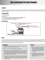
7KHVZLWFKHVGLDODQGWULPPHUVLQWKH¿JXUHDUHVKRZQLQWKHLQLWLDOVHWWLQJSRVLWLRQ
3OHDVHEHFDUHIXOQRWWRSXVKWKHVZLWFKWRRVWURQJO\
Grip Handle
A vibration motor is built into the grip handle
and racing timer time-up, low battery alarm,
telemetry alarm, etc. Can be generated by
vibration.
Digital Dial (DL1)
/Push switch 6 (PS6)
Power switch
Display switch
Digital Trim 2 (DT2)
(default throttle trim)
Digital Trim1 (DT1)
(default steering trim)
Digital Trim4 (DT4)
Steering wheel
Push switch 2 (PS2)
Push switch 3 (PS3)
Push switch 4 (PS4)
LED
Touch screen LCD
NFC
Home button
Hook
Nomenclature
Transmitter T7PX
High point spring
Convenient in trigger switch position
checks.
Mechanical ATL
adjusting screw
Throttle trigger
Digital Trim3 (DT3)
Digital Trim5 (DT5)
(default dual rate)
Push switch 1 (PS1)
Push switch 5 (PS5)
Digital Trim6 (DT6)
(default brake rate)
Wheel tension
adjusting screw
Trigger tension
adjusting screw
Battery cover
Trigger slide adjusting screw
Earphone Jack
(3.5mm stereo jack plug)
Telemetry data can be listened to with commer-
cial earphones.
Non-telemetry LED
(Lights when the telemetry function is off.)
Antenna
Cover
Communication port/SBus port
Charging jack

16
Before Using
Battery cover
Battery Replacement Method
1
Remove the battery cover from the transmitter by
sliding it in the direction of the arrow in the figure.
2
Remove the used batteries.
Caution
If you remove the dry cell battery box from the transmit-
ter, replace it carefully with the wiring on the same side
as before. Reinstalling the battery box in the opposite
direction could cause the wires to be disconnected.
3
Load the new AA size batteries. Pay very close at-
tention to the polarity markings and reinsert accord-
ingly.
4
Slide the battery cover back onto the case.
Battery Replacement Method
/RDGWKHIRXUEDWWHULHVLQDFFRUGDQFHZLWKWKHSRODULW\PDUNLQJVRQWKHEDWWHU\KROGHU
Disposal of the Dry Cell Batteries:
The method to dispose of used dry cell batteries depends on the area in which you reside. Dispose of the
batteries in accordance with the regulations for your area.
Caution
When running (cruising), do not use the dry cell battery box at the transmitter.
The accessory dry cell battery box is for performance checks. Do not use it for other than performance checks. The dry
cell batteries will be separated from the battery box contacts by shock and the power may be cut off. There is the danger
of collision if the power is cut while running (cruising). The use of Futaba genuine NiMH or LiFe batteries is strongly rec-
ommended.
Low Battery Alarm
,IWKHWUDQVPLWWHUEDWWHU\YROWDJHGURSVEHORZWKHXVDEOHUDQJHDQDXGLEOHDODUPZLOOVRXQG
and
"
/RZEDWWHU\
"
ZLOOEHGLVSOD\HG)RUGHWDLOVVHHSDJH6LQFHWKHXVDEOHUDQJHRI
1L0+EDWWHULHVDQG/L)HEDWWHULHVLVGLIIHUHQWWKHSRZHUVXSSO\XVHGPXVWEHVHWE\V\VWHP
VHWWLQJSDJH,IWKHEDWWHU\JRHVGHDGZKLOHUXQQLQJFUXLVLQJVLQFHWKHUHLVWKHGDQ
-
JHURIFROOLVLRQLPPHGLDWHO\UHFRYHUWKHYHKLFOHERDWDQGVWRSUXQQLQJFUXLVLQJ
Warning
When a low battery alarm is generated, cease operation immediately and retrieve the model.
If the battery goes dead while in operation, you will lose control of the model.
6OLGHEDWWHU\FRYHUZKLOHSUHVVLQJKHUH

Battery cover
6OLGHEDWWHU\FRYHUZKLOHSUHVVLQJKHUH
17
Before Using
Caution
When closing the battery cover, be careful that the battery cover does not pinch the battery lead
wires.
Shorting of the battery lead wires may lead to fire and abnormal heating and cause burns or fire disaster.
Battery Replacement Method
1
Refer to the previous description and remove
the transmitter battery cover.
When Using The Optional Battery
:KHQXVLQJDQRSWLRQDOUHFKDUJHDEOHEDWWHU\UHSODFHWKHEDWWHU\DVGHVFULEHGEHORZ
$OZD\VXVHWKHRSWLRQDO)7)%)7)%RU+7)%UHFKDUJHDEOHEDWWHU\
7KHW\SHRISRZHUVRXUFHXVHGPXVWEHVHOHFWHGWKURXJKWKHV\VWHPVHWWLQJSDJH
:KHQWKHWUDQVPLWWHUZLOOQRWEHXVHGIRUDORQJWLPHUHPRYHWKHEDWWHU\
2
After removing the dry cell battery box from the
transmitter, disconnect the connector.
Caution
If you remove the dry cell battery box from the trans-
mitter, replace it carefully with the wiring on the same
side as before. Reinstalling the battery box in the op-
posite direction could cause the wires to be discon-
nected.
3
Insert the connector of the new battery and load
the new battery into the transmitter.
4
Finish by installing the battery cover.

9M20A05401
(FUTM1725)
18
Before Using
Warning
With Balance Charger
(Example: When using the
)7)%%
with an optional charger)
1
Remove the battery cover.
2
Disconnect the battery from the T7PX.
3
Balance charging cannot be done through the
transmitter. You must remove the LiFe battery to do
this charge.
Charging A LiFe Battery
(Example: When using the
)7)%%
the special charger)
1
Plug the transmitter cord of the special charger into
the charging jack on the rear of the transmitter.
2
Plug the charger into an AC outlet.
3
Check that the charging LED lights red.
4
When charging is completed, the ccharging LED
lights green. Disconnect the charge plug and dis-
connect the AC plug of the charger.
7KHFKDUJLQJWLPHZKHQFKDUJLQJWKH)7)-
%9EDWWHU\ZLWKWKHRSWLRQDOVSHFLDOFKDUJHU
LVDSSUR[LPDWHO\KRXUV
:KHQWKH/L)HEDWWHU\ZLOOQRWEHXVHGIRUDORQJ
WLPHWRSUHYHQWLWIURPGHWHULRUDWLQJ ZH UHFRP-
PHQGWKDWLWEHNHSWLQDERXWWKHKDOIFDSDFLW\VWDWH
LQVWHDGRI IXOO\ FKDUJHG$OVR EH FDUHIXO WKDW WKH
EDWWHU\ GRHVQRWHQWHUWKHRYHUGLVFKDUJHGVWDWH
GXH WR VHOIGLVFKDUJH 3HULRGLFDOO\ DERXW HYHU\
PRQWKVFKDUJHWKHEDWWHU\,QDGGLWLRQDOZD\VUH-
PRYHWKHEDWWHU\IURPWKHPRGHODQGVWRUHLWLQD
GU\FRROSODFH&WR&
Over current protection
7KH WUDQVPLWWHU FKDUJLQJ FLUFXLW LV HTXLSSHG ZLWK
DQRYHUFXUUHQWSURWHFWLRQFLUFXLW$,IWKHEDW-
WHU\LVFKDUJHGZLWKDTXLFNFKDUJHUIRURWKHUWKDQ
GLJLWDO SURSRUWLRQDO 5& VHWV LW PD\ QRW EH IXOO\
FKDUJHG
7KHFKDUJLQJWLPHZKHQFKDUJLQJWKH+7)%
EDWWHU\ZLWKWKHRSWLRQDOVSHFLDOFKDUJHULVDSSUR[L-
PDWHO\ KRXUV +RZHYHU ZKHQWKHEDWWHU\ KDV
QRWEHHQXVHGIRUVRPHWLPHUHSHDWFKDUJLQJRU
WLPHVWRDFWLYDWHWKHEDWWHU\
Charging A NiMH Battery
(Example: When using the HT5F1800B with the special charger)
1
Plug the transmitter cord of the special charger into
the charging jack on the rear of the transmitter.
2
Plug the charger into an AC outlet.
3
Check that the charging LED lights.
When Charging For The Optional Battery
%DODQFHFKDUJLQJFRQQHFWRUIRU/L)HEDWWHU\FKDUJHU
)ROORZWKHGLUHFWLRQVRIWKHRSWLRQDO/L)HFKDUJHUVLQXVH
LiFe battery is removed from the transmitter.
Make sure not to peel off the battery film, or make any scratch by a cutter knife or the sharp edges of
metal components.
Make sure not to soak or get the battery wet with water or seawater.
Make sure not to use a deformed or swollen battery.
There is a risk of explosion or fire, which is very dangerous.
Charging jack

Power & Display Switch
19
Before Using
Warning
Caution
Never plug it into an outlet having other than the indicated voltage.
Plugging the charger into the wrong outlet could result in an explosion or fi re.
Do not insert and remove the charger when your hands are wet.
It may cause an electric shock.
Always use the special charger or a quick charger for digital proportional R/C sets to charge a digital
proportional R/C set battery.
Overcharging a NiMH battery can result in burns, fi re, injuries, or loss of sight due to overheating, breakage, or electrolyte
leakage.
Do not plug the charger to the charging jack, if the battery is not connected to the transmitter.
The transmitter may be damaged.
When the charger is not in use, disconnect it from the AC outlet.
Do this to prevent accidents and to avoid overheating.
Power & Display Switch
7KHSRZHUVZLWFKDQGGLVSOD\VZLWFKDUHSXVKVZLWFKHV
:KHQWKHSRZHUVZLWFK3:5LVKHOGGRZQRSHUDWLRQVWDUWVE\
WUDQVPLWWLQJUDGLRZDYHV:KHQWKHGLVSOD\VZLWFK'63LVKHOG
down, the transmitter side data can be checked and set. When
WKHSRZHULVWXUQHGRIILIWKHSRZHUVZLWFKRUGLVSOD\VZLWFKLV
KHOGGRZQWKHSRZHULVWXUQHGRII,IERWKVZLWFKHVDUHSUHVVHG
VLPXOWDQHRXVO\WKHSRZHULVWXUQHGRIITXLFNO\
OFFDSP PWR
When the power is turned off,
if the power switch or display
switch is held down, the power
is turned off. If both switches
are pressed simultaneously, the
power is turned off quickly.
Radio waves are not
being
transmitted.
"Display mode RF off"
is displayed
Radio waves are
being transmitted.
When you do not run, turn OFFIt cannot operate. It can operate.

The current system is displayed.
(T-FHSS SR /T-FHSS /S-FHSS /FASST)
When turned on by DSP switch, "Dis-
play" is displayed
T-FHSS /S-FHSS /FASST - Response type
(Digital servo /Analog servo)
T-FHSS SR - SR mode on/off
(SR mode setting channel is a red SR mark.)
*The figure above is partly processed for explanation, so it is different from the actual screen display.
Trim/dial lock display mark
20
Before Using
Display When Power Switch Is Turned On
DT1
DT2
DT3
DT4
DT5
DT6
DL1
Total timer or clock display (H:M)
Battery voltage display
Upper: Steering trim display
Lower: Throttle trim display
Menu button
User menu button
Racing timer
Trim/dial lock display mark
Micro SD card mark
Function names and rate as-
signed to dials are displayed.
Model #, Model name (15 characters)
User name (15 characters)
Telemetry function
Receiver -> Transmitter
The reception strength is shown.
Servo operation of each channel can be
checked.
(S-FHSS system Ch.1 to Ch.7)
Power Off Forgotten Alarm & Auto Power Off
$W73;LQLWLDOL]DWLRQLIVWHHULQJZKHHOWKURWWOHWULJJHUSXVKVZLWFKHGLWEXWWRQRURWKHU
RSHUDWLRQLVQRWSHUIRUPHGZLWKLQPLQXWHVDQDXGLEOHDODUPZLOOVRXQGDQGWKHPHVVDJH
"
:DUQLQJ$XWRSRZHURII
"
ZLOODSSHDU
)RUGHWDLOVVHHSDJH
.
,IVWHHULQJZKHHOWKURWWOHWULJJHUSXVKVZLWFKHGLWEXWWRQRURWKHURSHUDWLRQLVSHUIRUPHGWKH
DODUPLVUHVHW$OVRWXUQRIIWKHSRZHUZKHQWKHWUDQVPLWWHULVQRWLQXVH,IWKHDODUPLVQRW
UHVHWWKHDXWRSRZHURIIIXQFWLRQZLOODXWRPDWLFDOO\WXUQRIIWKHSRZHUDIWHUPLQXWHV,I\RX
GRQRWZDQWWRXVHWKLVDODUPDQGWKHDXWRSRZHURIIIXQFWLRQWKH\FDQEHGLVDEOHGE\V\VWHP
VHWWLQJ
SDJH
Trim/Dial Lock
73;VHWXSDQGRSHUDWLRQE\GLJLWDOWULP'7'7'7'7'7 DQG '7 DQGGLDOV
'/FDQEHSURKLELWHG
Setting
1
When the HOME button is pressed for about 1 second at the initial
screen, a confirmation beep is generated and the trim/dial lock display
mark appears on the screen.
Clearing
1
Edit button lock and trim/dial lock can be cleared in the initial screen
state by the same method as the setting described above. (The trim/dial
lock display disappears from the screen.)
/