Page is loading ...

en
Operating manual
We move people.
Multifunction-Wheelchair
Model 9.072

2
Contents
Meaning of the applied markers 5
Introduction 5
List of models 5
Indications 5
Acceptance 5
Specifications 5
Use 6
Adjustment 6
Reinstallment 6
Life span 7
Overview 8
Brake 9
Pressure brake - user 9
Locking the brakes 9
Releasing the brakes 9
Service brake 9
Drum brake for accompanying persons 10
Function as operating brakes 10
Leg supports 11
Lower leg support 11
Footplates 11
Leg support upper part 12
Turning the leg supports to the side 12
Swivelling in the leg supports 13
Removing the leg supports 13
Attaching the leg supports 13
Mechanically height-adjustable leg supports 14
Lifting/lowering the leg support 14
Adjusting the height of the footplate 15
Height adjustment of the calf pad 15

3
Arm supports 16
Removing the arm support 16
Inserting the arm support 16
Adjustment of the armrest height 17
Depth adjustment of the arm support cushions 17
Repositioning the arm support cushion 17
Back support with angle adjustment 18
Adjusting the angle of the back support 18
Folding down the back support 19
Unfolding the back support 19
Back support upholstery 20
Head support 21
Seat 21
Seat inclination 22
Adjustment of seat inclination 22
Rising aid 23
Torso supports 23
Removing the torso support 23
Wheels 24
Drive wheels 24
Tyre damage on pneumatic tyres 24
Handrims 25
Tilt protection 25
Insertable tilt protection 25
Retaining strap 26
Therapy table 26
Folding/Unfolding 27
Folding the wheelchair 27
Unfolding the wheelchair 27

4
Basic safety information 28
Accompanying person 28
Transfer out of the wheelchair 28
Reaching for objects 28
Driving on falling, rising or transverse gradients 28
Crossing obstacles 29
Loading the wheelchair 30
Transport in vehicles 30
Transport safety of the empty wheelchair 30
Transport of people inside a motor vehicle 30
Transport in public methods of transportation 30
Driving on public highways 31
Cleaning 31
Finish 31
Disinfection 31
Disposal 32
Maintenance 32
Maintenance 32
Maintenance schedule 33
Technical data 35
Tyre pressure of pneumatic tyres 35
Data according to ISO for model 9.072 36
Further technical data for model 9.072 37
Meaning of the symbols on the washing instruction 38
Meaning of the labels on the wheelchair 39
Meaning of the symbols on the type plate 40
Inspection certificate 41
Warranty / Guarantee 42
Warrantee / Guarantee section 43
Inspection certificate for transfer 43

5
MEANING OF THE AP-
PLIED MARKERS
Safety instructions with a coloured back-
ground are mandatory and need to be
observed under any circumstance!
☞ This symbol indicates tips and recom-
mendations
[ ] Reference to a picture number
( ) Reference to a function element within
a picture.
INTRODUCTION
Read and observe this manual before first
operation. Children and juveniles should
read this documentation together with
their parents respectively a supervisor or
accompanying person before first use.
This operating manual is to help you get ac-
customed to the handling of the wheelchair
as well as to prevent accidents.
☞ Please note that the illustrated equip-
ment variants can deviate from your
model.
We have therefore also listed chapters with
options that might not be applicable for
your vehicle.
Users with visual impairments can find the
PDF-files together with further information
on our website:
< www.meyra.com >.
☞ Contact your specialist dealer when re-
quired.
Information about product safety, possible
recalls and general handling instructions of
our products can be found in the < Infozen-
trum > on our website:
< www.meyra.com >.
Our implemented assembly groups and
components fulfil the demands of the
norms of correspondence acc. to EN 12183
for durability against inflaming.
LIST OF MODELS
This operating manual applies to the follow-
ing models:
Model 9.072
INDICATIONS
In case of allergic reactions, skin rashes
and/or pressure sores during the use of
the wheelchair sores contact a doctor im-
mediately.
If the following indications occur we rec-
ommend the application of this mobility
product:
☞ Provision with a handrim wheelchair
with seat camber and manual seat ad-
justment is then advised when long
term upright sitting in a common
wheelchair is no longer possible for the
user due to his condition and the per-
son in need of care spends long peri-
ods inside the wheelchair.
ACCEPTANCE
All products are checked for faults and
packed in special boxes.
☞ However, we request that you check
the vehicle for possible transport dam-
age immediately on receipt – prefera-
bly in the presence of the carrier.
☞ The packaging of the wheelchair
should be stored for a further transport
that might become necessary.

6
SPECIFICATIONS
The wheelchair was developed for adults
and adolescents. The wheelchair solely
serves to transport one person in the seat
and not as a hauling aid, transporter or
similar. The wheelchair serves to ease care
measures and for relief and support of the
person in need of care. On the version with
large drive wheels, smaller changes in posi-
tion of the wheelchair in rooms can be car-
ried out by the user himself with help of the
handrims.
USE
Do not reach into the spokes or grip the
tyres of the rotating wheels. – Danger of
injury!
Do not reach into the space between the
pressure brake and the tyre when propel-
ling the wheelchair. – Danger of injury!
Avoid a jerky propulsion of your wheel-
chair. – Danger of tipping over or tilting!
Do not use the wheelchair without at-
tached leg supports and arm support
units!
Your wheelchair with a seat width of more
than 500 mm is not suited for transport in
a train.
The wheelchair is applicable on level, firm
surfaces and can be used as follows:
– for indoors (e.g. apartment, day care),
– outdoors (e.g. paved paths in parks),
Never expose the wheelchair to extreme
temperatures and damaging environmental
conditions, such as sunlight, extreme cold
or salty water.
Sand and other dirt particles can seize on
moving parts and render them without
function.
Use only the handrims on the drive wheels
to propel your wheelchair.
You must not let yourself be carried in your
wheelchair by having the wheelchair lifted
from the floor. Parts that are not securely
fixed, e.g. side elements or leg supports, can
come away and thus cause an accident.
☞ The wheelchair is a vehicle and not a
carrying device.
Only apply the wheelchair within the
scope of the specifications and limitation
described in chapter Technical data on
page 35.
In certain configurations your wheelchair
might exceed the maximum dimensions of
emergency routes.
☞ Always make sure whether possible es-
cape routes are wide enough for your
wheelchair.
ADJUSTMENT
Always have adaptation and adjustment
work carried out by a specialist dealer.
The wheelchair offers manifold adjustment
possibilities to individual vital statistics.
The wheelchair should be adapted to your
needs by a specialist dealer before the first
use. The adaptation will take into account
the driving experience, the physical limits of
the user and the main place of use of the
wheelchair.
☞ We recommend a regular control if
the wheelchair adjustment in order to
ensure a long-term optimal provision
even with changing illness/handicap
patterns of the user.

7
REINSTALLMENT
The wheelchair is suited for reinstallment.
With the building block system the wheel-
chair can be fit to accommodate different
handicaps body sizes. Before reimplemen-
tation the wheelchair is to undergo a com-
plete inspection.
☞ Hygienical measures required for rein-
stallment are to be carried out accord-
ing to a validated hygienic plan and
must include disinfection.
LIFE SPAN
We expect an average life span of about
4 years for this product, as far as the product
is applied for its designated purpose and all
maintenance and service guidelines. The life
span of your product depends upon the fre-
quency of use, the application environment
and care. The implementation of spare parts
can prolong the life span of the product. As
a rule spare parts are available up to 5 years
after production is discontinued.
☞ The indicated lifespan does not consti-
tute additional guarantee.

1
6
4
5
8
9
12
13
11
14
7
2
3
10
8
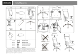
Pos. Description
(1) Push handle
(2) Pushing bar
(3) Head support
(4) Back support
(5) Arm support
(6) Seat cushion
(7) Leg support
OVERVIEW
The overview shows, representative for all models, the most important components of the
care wheelchair.
(8) Footplate
(9) Steering wheel
(10) Type plate
(11) Brake lever – pressure brake
(12) Locking knob – Quick release axle
(13) Handrims
(14) Driving wheel

1
2
3
4
9
BRAKE
Arrange an immediate repair of the brakes
by your specialist workshop if the braking
performance reduces.
By locking the brakes with the brake lever
(1), the wheelchair is secured against rolling
away unintentionally (parking brake).
Depending on the version, the wheelchair
can be equipped with pressure brakes (2) or
with drum brakes (3).
Pressure brake - user
Locking the brakes
To secure the wheelchair against any unin-
tentional rolling, press both brake levers for-
ward all the way [4].
☞ It should not be possible to push the
wheelchair forward when both brakes
are locked.
Releasing the brakes
Pull both brake levers back all the way [2].
Service brake
The wheelchair is braked down with help of
the handrims.
☞ If needed use suitable gloves in order to
brake down the wheelchair.

1
C
A
B
2
10
Drum brake for accompanying
persons
The drum brake is activated by the accom-
panying person through the brake levers (1).
Function as operating brakes
Use both brake levers evenly and only light-
ly in order to achieve a controlled decelera-
tion of the wheelchair.
Locking the drum brakes
Pull both brake levers (1) and press the lock-
ing latch (2) forward.
Release the brake lever. – Depending on the
adjustment the latch engages in the first (A)
or second (B) locking position and activates
the brake.
☞ If the third locking position (C) is re-
quired to activate the brake, it must be
readjusted by a specialist workshop.
Loosen the drum brakes
Pull both brake levers (1) until the latches
(2) automatically jump out of the locking
points.
Let go of both brake levers. – The parking
brakes are released and the wheelchair
ready for use.

3
4
1
2
11
LEG SUPPORTS
Before any actions on the leg supports
the wheelchair is to be secured against
unintentional rolling motions.
☞ Therefore observe chapter Brake on
page 9.
Lower leg support
For entry into, exiting the wheelchair or
"scuttling" (forward motion of the wheel-
chair with the feet) the footplates (1) are to
be folded up and the calf pads (2) folded
outward in driving direction [3].
☞ Check the locking points!
– Remove both feet from the footplates.
☞ Before starting to drive the footplates
resp. footboard need to be folded back
down [3] and the calf belt attached.
Footplates
The footplates can be folded outward and
up [3] resp. inward and down [4].

2
1
3
12
LEG SUPPORT UPPER
PART
The upper leg support with an inserted
lower leg support is termed leg support [1].
Turning the leg supports to the
side
Leg supports turned to the side are re-
leased automatically and can easily come
off. Note this when handling (e.g. trans-
port).
For easy transfer out of/into the wheelchair
as well as driving closer to a closet, bed or
bathtub the leg supports can be swivelled
outward [2].
☞ Remove the calf belt, if applicable, be-
fore swivelling away the leg supports.
☞ View chapter Lower leg support on
page 11.
Fold up the footplates in order to swivel the
leg supports to the sides.
☞ Therefore observe chapter Lower leg
support on page 11.
Afterwards pull or press the respective lock-
ing lever (3) backward and swivel the corre-
sponding leg support outward.

1
2
13
Swivelling in the leg supports
For inward swivelling, let the leg supports
swivel forward until the lock audibly engag-
es [1].
☞ After audibly swivelling the leg sup-
ports inward check the respective lock-
ing device.
☞ Afterwards observe the chapter
Lower leg support on page 11.
Removing the leg supports
For easy transfer into and out of the wheel-
chair as well as a reduced wheelchair length
(important for transport) the leg supports
can be removed [2].
☞ Fold the calf pads outward before re-
moving the leg supports.
☞ Therefore observe chapter Lower leg
support on page 11.
For removal first swivel the leg support side-
ways [2] and then remove them toward the
top [1].
☞ Therefore observe chapter Lower leg
support on page 11.
☞ Watch for possible danger of jam-
ming!
Attaching the leg supports
For inserting press the leg supports, swiv-
elled to the side, parallel to the front frame
tube and lower it into place. – In doing so
the holding pin must slide into the frame
tube.
☞ After attachment swivel the leg sup-
ports inward [1].
☞ Therefore observe chapter Technical
data on page 35.

1
14
Mechanically height-adjustable
leg supports
Never put the free hand into the adjust-
ment mechanism. Have the leg support
secured by an accompanying person
against unintentionally falling down.
Do not let the leg support drop on its
own weight. – Danger of injury!
Lifting/lowering the leg support
Before lifting/lowering relieve the leg sup-
port by an accompanying person by slightly
lifting it up.
Afterwards loosen the clamping lever (1)
and have the leg support lifted/lowered
slowly to the desired level by an accompa-
nying person.
After the adjustment retighten the clamp-
ing lever (1).

2
4
3
1
15
Adjusting the height of the footplate
Loosen the clamping screw (1) to adjust the
height.
☞ Loosen the clamping screw (1) so far
that no damage to the coating occurs
during the adjustment.
☞ Observe the maximum extension mark
(2).
Telescope the footplate to the desired
height and then retighten the clamping
screw (1).
Height adjustment of the calf pad
Loosen the respective clamping screws (4)
to adjust the height of the calf pad (3).
After the height adjustment retighten the
clamping screw (4).

1
2
4
3
16
ARM SUPPORTS
Do not use the arm supports [1] to lift or
carry the wheelchair.
Do not drive without the arm supports.
No not grab between the frame and arm
support. – Danger of squashing!
When the wheelchair is being pushed
by an attendant the user is to place his
hands onto the arm cushions or in his lap
and not at the sides between body and
arm support. – Danger of squashing the
fingers!
Removing the arm support
To remove the arm support, loosen the
clamping screw (2) first and then remove
the arm support toward the top [3].
☞ If necessary previously remove the tor-
so support cushion.
☞ Therefore observe chapter Removing
the torso support on page 23.
Inserting the arm support
For inserting the arm support, first slide
the arm support as far as possible into the
bracket (4) and then tighten the clamping
screw (2).

1
2
3
4
17
Adjustment of the armrest height
Before loosening the clamping screws
(2) secure the arm support against falling
down with your hand. – Danger of jam-
ming!
The maximum arm support height has
been reached when the marking on the
square tube is visible.
First loosen the clamping screw (1) of the
height stopper before adjusting the height
of the arm support.
Afterwards loosen the clamping screw (2).
☞ Loosen the clamping screws (1)+(2) so
far that no damage to the coating oc-
curs during the adjustment.
Hold the arm support at the desired height
and then tighten the clamping screw (2).
Push the height stopper (3) down to the
stop and tighten the clamping screw (1).
☞ If necessary the clothes guard can
be adjusted to the new arm support
height by the specialist dealer.
Depth adjustment of the arm
support cushions
To adjust the arms support cushion accord-
ing to the seat depth, loosen the respective
clamping screw (4).
☞ After the adjustment by sliding the arm
support cushions, retighten the respec-
tive clamping screws (4).
Repositioning the arm support cushion
After the required depth adjustment the
arm support cushion can be displaced by
two further positions.
To displace the arm support cushion un-
screw the respective clamping screw (4).
☞ After displacement of the arm support
cushions, reinsert and tighten the re-
spective clamping screws (4).

1
2
3
18
BACK SUPPORT WITH AN-
GLE ADJUSTMENT
Before any actions on the back supports
the wheelchair is to be secured against
unintentional rolling motions.
☞ Therefore observe chapter Brake on
page 9.
Adjusting the angle of the back
support
The angle of the back support [1] is contin-
uously adjustable through the gas pressure
spring.
Activate the right lever (3) on the push han-
dle for continuous angle adjustment of the
back support.
☞ In doing so use both push handles,
resp. the push bar as a lever and adjust
the back support accordingly. – Danger
of overturning!
☞ The adjustment should only be car-
ried out under the weight of the
user.
After the angle adjustment release the lever
(3).
☞ Check to ensure that the back support
and seat unit are locked in place.

1
2
3
5
4
19
Folding down the back support
Fold open the safety latch (2) first for folding
over the back support [1], then remove the
pin (3).
☞ All the while hold the back support in
position with one hand on the push bar
or handle in order to prevent it from tilt-
ing over to the back.
☞ The loose distancers might fall and roll
off. – Do not loose the distancers!
Afterwards fold the back support down [1].
☞ Reinsert the pin after releasing the gas
spring for the back support [4], in order
to prevent loss of it and also the dis-
tancers.
Unfolding the back support
After raising the back support [4] lift the gas
pressure spring back up and hang it into
place. Then insert the pin (3) and distancers
and fold the safety latch (2) to closes posi-
tion [5].
☞ Check the locking device after raising
the back support up and reinserting
the pin.
☞ Keep the pin clean at all times for flaw-
less function.

1
2
3
20
Back support upholstery
The back support upholstery is attached to
the back shell with velcro straps [1] and can
be pulled off for cleaning or maintenance
[2].
☞ The cover can be removed with the zip-
per for washing.
☞ Therefore observe the label with the
washing instruction (3).
To replace the back support upholstery
align it according to the back shell and press
it on [1].
/