Follett chewblet 7FS100A Installation, Operation And Service Manual
- Category
- Ice cube makers
- Type
- Installation, Operation And Service Manual
This manual is also suitable for

Installation and Service Videos:
www.follettice.com/servicevideolibrary
00976738R13
801 Church Lane • Easton, PA 18040, USA
Toll free (877) 612-5086 • +1 (610) 252-7301
www.follettice.com
230 V/50 Hz and 220 V/60 Hz
Installation, Operation and Service Manual
Serial numbers above K70778
Countertop and Freestanding Ice and Water
Dispenser with Chewblet
®
Ice Machine
_7CI100A, _7FS100A, _15CI100A, _15FS100A
_7FS100A
_7CI100A
_15FS100A
_15CI100A
Welcome to Follett
Follett equipment enjoys a well-deserved reputation for excellent performance, long-term reliability and outstanding
after-the-sale support. To ensure that this equipment delivers that same degree of service, review this guide
carefully before you begin your installation.
Should you need technical help, please call our Technical Service group at (877) 612-5086 or (610) 252-7301.
Please have your model number, serial number and complete and detailed explanation of the problem when
contacting Technical Service.
Getting Started
After uncrating and removing all packing material, inspect the equipment for concealed shipping damage. All freight
is to be inspected upon delivery. If visible signs of damage exist, please refuse delivery or sign your delivery receipt
"damaged." Follett Customer Service must be notied within 48 hours. Wherever possible, please include detailed
photos of the damage with the original packaging so that we may start the freight claim process.

2 Dispenser and Ice Machine 230 V/50 Hz and 220 V/60 Hz
Contents
Welcome to Follett. . . . . . . . . . . . . . . . . . . . . . . . . . . . . . . . . . . . . . . . . . . . . . . . . . . . . . . . . . . . . . . . . . . . . . . . . . . . . . 1
Getting Started .............................................................................. 1
Before You Begin ............................................................................... 3
Specications ................................................................................. 4
Dimensions ................................................................................. 4
Ambient Information .......................................................................... 4
Plumbing ................................................................................... 4
Specications ................................................................................. 5
Water ..................................................................................... 5
Clearances ................................................................................. 5
Electrical ................................................................................... 5
Refrigeration ................................................................................ 5
Heat Rejection .............................................................................. 5
_7 Series Detailed Drawing .................................................................... 6
_15 Series Detailed Drawing ................................................................... 7
Installation .................................................................................... 8
Countertop Installation ........................................................................ 8
Freestanding Installation ....................................................................... 9
Maintenance/Cleaning Mode .................................................................... 12
Accessing Internal Components ................................................................. 12
Filter Display Indicator Activation ................................................................ 13
Cleaning and Sanitizing Procedure ............................................................... 14
Service ...................................................................................... 15
LED Indicator Description ..................................................................... 15
Evaporator Disassembly ...................................................................... 16
Evaporator Assembly ........................................................................ 19
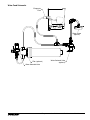
Water Feed Schematic ....................................................................... 23
Bin Melt Water/Evaporator Feed/Clean Out System Schematic ....................................... 24
Vent System Schematic ...................................................................... 24
Refrigeration Schematic ...................................................................... 25
Condenser Fan Motor Removal (_7 Series Shown) ................................................ 26
User Interface Display Identication ............................................................. 27
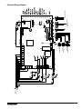
Electrical Wiring Diagram ..................................................................... 29
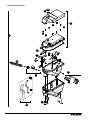
Parts ........................................................................................ 30
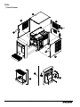
_7 Series Exterior ........................................................................... 30
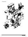
_7 Series Interior ........................................................................... 32
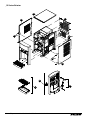
_15 Series Exterior .......................................................................... 34
_15 Series Interior .......................................................................... 36
_7 Series Bin Assembly ...................................................................... 38
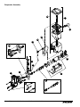
Evaporator Assembly ........................................................................ 42
Base Stand ................................................................................ 44

Dispenser and Ice Machine 230 V/50 Hz and 220 V/60 Hz 3
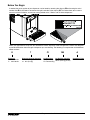
Before You Begin
If needed, the serial number of your dispenser can be found by removing the drip tray ❶ and locating the serial
number label ❷. A QR Code is located on the right hand side of the drip tray ❸. This code allows you to access
manuals, technical bulletins, and on-line training related to the 7 Series and 15 Series dispensers.
2
1
3
Check your paperwork to verify that you received the correct dispenser. Follett conguration numbers are designed
to provide information about the type of dispenser you are receiving. The following is an explanation of the different
model numbers.
E 7 CI 100 A
Electrical
E 230 V/50 Hz
C 220 V/60 Hz
Dispenser Storage Capacity
7 7 lb (3.1 kg)
15 15 lb (6.8 kg)
Conguration
CI Countertop
FS Freestanding
Ice Machine Capacity
100 lb (45.3 kg) per day
Condenser Type
A Air-cooled

4 Dispenser and Ice Machine 230 V/50 Hz and 220 V/60 Hz
CAUTION!
§ Do not tilt unit further than 30° off vertical during uncrating or installation.
§ Dispenser bin area contains mechanical, moving parts. Keep hands and arms clear of this area at all times. If access to this area is
required, power to unit must be disconnected rst.
§ This appliance is not suitable for installation in an area where a water jet could be used.
§ This appliance must not be cleaned by a water jet.
§ User maintence should not be done by children.
§ Follett recommends a Follett water lter system be installed in the ice machine inlet water line (standard capacity #00130229, high capacity
#00978957, carbonless high capacity #01050442).
§ Prior to operation clean the dispenser in accordance with instructions found in this manual.
§ Do not block air intake or exhaust.
§ This appliance should be permanently connected by a qualied person in accordance with application codes.
§ A qualied person shall provide a readily accessible disconnect device incorporated into the xed wiring.
§ If the supply cord is damaged, it must be replaced by the manufacturer, its service agent or similarly qualied persons in order to avoid a
hazard.
§ This appliance can be used by children aged 8 years and above and persons with reduced physical, sensory, or mental capabilities, or
lack of experience and knowledge if they have been given supervision or instruction concerning use of the appliance in a safe way and
understand the hazards involved. Children should be supervised to ensure that they do not play with the appliance.
§ This appliance is designed for commercial use.
§ WARNING! To avoid a hazard due to instability of the appliance, it must be xed in accordance with the instructions.
§ Warranty does not cover exterior or outside installations.
§ To reduce risk of shock, disconnect power before servicing.
§ Connect to potable water supply only.
§ Ice is slippery. Maintain counters and oors around dispenser in a clean and ice-free condition.
§ Ice is food. Follow recommended cleaning instructions to maintain cleanliness of delivered ice.
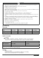
Specications
Dimensions
_7CI100A _7FS100A _15CI100A _15FS100A
Width 40 cm (14.50") 40 cm (14.50") 40 cm (14.50") 40 cm (14.50")
Depth 56.2 cm (22.12") 56.2 cm (22.12") 59.7 cm (23.50") 59.7 cm (23.50")
Height 44.5 cm (17.50") 106.4 cm (41.88") 57.2 cm (22.50") 118.7 cm (46.75")
Unit Shipping Weight 41 kg (90 lb) 54.4 kg (120 lb) 45.4 kg (100 lb) 60 kg (130 lb)
Ambient Information
CAUTION!
The _7CI100A, _7FS100A and _15CI100A, _15FS100A are for indoor use only. Designed for
commercial use. Follett is not able to provide in-house services for residential installations.
Maximum* Minimum*
Air Temperature
†
38 C (100 F) 10 C (50 F)
Water Temperature 32.2 C (90 F) 4.5 C (40 F)
Water Pressure 70 psi (483 kpa) 69 kpa (10 psi)
Relative Humidity 55% at 25.5 (78 F)
* Use outside of these limitations is misuse and will void warranty.
† Best performance is achieved between 27 C (80 F) and 10 C (50 F).
Plumbing
§ Water Inlet: 1/4" MPT
§ Optional Drain Accessory Kit (item# 00956375 or 00981977): 1/2" ID tubing
§ Water shut-off recommended within 1.5 m (5 ft) of dispenser

Dispenser and Ice Machine 230 V/50 Hz and 220 V/60 Hz 5
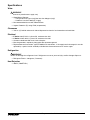
Specications
Water
WARNING!
Connect to potable water supply only.
§ Water Mineral Content:
– TDS: greater than 5 ppm (mg/l) but less than 400 ppm (mg/l)
– Hardness: Less than 200 mg/l (12 gpg)
§ Not recommended for use with softened water
§ Ingress Protection (IP) rating: IPX0 (no protection)
Clearances
§ 7.62 cm (3") behind and on each side of dispenser for electrical and connection and ventilation
Electrical
§ E Series: 230 V, 50 Hz, 1 phase, 5A, maximum fuse 10A
§ C Series: 220 V, 60 Hz, 1 phase, 5A, maximum fuse 10A
§ Connect to dedicated 10A circuit, fuse or breaker.
§ Must be grounded - requires 3-prong outlet. Do not remove ground.
§ Replacement cord instructions, type IEC 60320-C13 attachment - If the supply cord is damaged, it must be
replaced by a special cord or assembly available from the manufacturer or its service agent.
Refrigeration
WARNING!
Do not damage the refrigerant circuit. Refrigerant can cause personal injury and/or damage dispenser.
§ Refrigerant R134a – 204 grams (7.2 ounces)
Heat Rejection
§ 498 W (1700 BTU/hr)

6 Dispenser and Ice Machine 230 V/50 Hz and 220 V/60 Hz
Specications (continued)
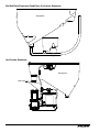
_7 Series Detailed Drawing
Countertop models
Freestanding models
62 cm
(24.41")
37.1 cm (14.62")
44.7 cm
(17.59")
56.2 cm (22.12")
20.3 cm
(8.00")
37.1 cm (14.62")
17.5 cm
(6.88")
44.7 cm
(17.59")
7.62 cm
(3.00")
6.04 cm
(2.38")
1/4" MPT
water inlet
56.2 cm (22.12")
37.1 cm (14.62")
44.7 cm
(17.59")
20.3 cm
(8.00")
37.1 cm (14.62")
17.5 cm
(6.88")
44.7 cm
(17.59")
7.62 cm
(3.00")
6.04 cm
(2.38")
1/4" MPT
water inlet

Dispenser and Ice Machine 230 V/50 Hz and 220 V/60 Hz 7
Specications (continued)
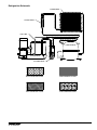
_15 Series Detailed Drawing
Freestanding models
Countertop models
57.2 cm
(22.50")
37.1 cm (14.62")
37.1 cm (14.62")
56.2 cm (22.12")
56.2 cm (22.12")
57.2 cm
(22.50")
62.2 cm
(24.50")
59.7 cm (23.50")
119.4 cm
(47.00")
23.50" (59.7 cm)
37.1 cm (14.62")
1/4" MPT
water inlet
6.10 cm
(2.40")
20.3 cm
(8.00")
57.2 cm
(22.50")
17.5 cm
(6.88")
7.57 cm
(2.98")
37.1 cm (14.62")
1/4" MPT
water inlet
6.04 cm
(2.38")
20.3 cm
(8.00")
57.2 cm
(22.50")
17.5 cm
(6.88")
7.62 cm
(3.00")

8 Dispenser and Ice Machine 230 V/50 Hz and 220 V/60 Hz
Installation
CAUTION!
No service or maintenance should be performed until the technician
has thoroughly read this service manual. Except for routine cleaning
and sanitizing, only qualied technicians should attempt to service
or maintain this equipment.
Countertop Installation
The _7 Series countertop model is designed to t on counters underneath
standard mounted cabinets, this does not apply to _15 Series models. See
page 4 for dimensions. Installation instructions for freestanding model
may be found on page 9.
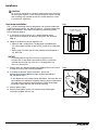
1. A clearance of at least 7.62 cm (3") is required behind and on
each side of the dispenser for electrical connection and ventilation
(Fig.1).
2. Rough-in the electrical service and water line.
§ Electrical: 230 V, single phase. The dispenser is provided with a
2.4m (8 ft) power cord with choice of CEE 7/7, AS 3112, or BS1363
plug.
§ Water: supply line (with shut-off valve) connects to the dispenser's
1/4"MPT inlet.
NOTICE!
If installing optional Drip Tray Drain Kit or Leg Accessory,
complete those steps before proceeding. Refer to instructions
included with the Drip Tray Drain Kit, or see page 9 for Leg
Accessory instructions.
Fig. 1
3. Connect water line. Recommended routing (Fig. 2) allows easy access
to water for cleaning and sanitizing procedure.
4. If installing the optional internal water lter*, please see
Maintenance/Cleaning Mode on page 12 before proceeding. If
not, proceed to step 5.
* If your dispenser has the internal water lter option, the water lter must
be installed for the dispenser to operate. Because internal components
will need to be accessed for both procedures, Follett recommends
installing the water lter just prior to initial sanitizing.
5. Connect power supply.
6. Sanitize the dispenser prior to use (see the Initial Sanitizing Kit
instructions shipped with this unit).
Fig. 2
countertop models
minimum 7.62 cm (3")
clearance required
91.4 cm (3')
1/4" MPT
Plug
Valve

Dispenser and Ice Machine 230 V/50 Hz and 220 V/60 Hz 9
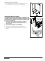
Optional Leg Accessory Installation
CAUTION!
Use caution when tipping the dispenser during leg installation. Do
not lay unit on back or side. DO NOT EXCEED 30° angle. Tipping
more than 30° can result in compressor malfunction.
1. If installing optional 4" Leg Accessory (item# 00956300), place a
12.7 cm (5") spacer underneath the dispenser to ease installation.
2. Remove four plastic, thread-protecting plugs from bottom of
dispenser.
3. Screw each leg into chassis (Fig. 3).
Fig. 3
Freestanding Installation
Installation instructions for countertop model may be found on Countertop
Installation on page 8.
1. A clearance of at least 3" (7.62 cm) is required behind and on
each side of the dispenser for electrical connection and ventilation
(Fig.4).
2. Rough-in the electrical service and water line.
§ Electrical: 230V, single phase. The dispenser is provided with an
2.4m (8ft) power cord with choice of CEE 7/7, AS 3112, or BS 1363
plug.
§ Water: supply line (with shut-off valve) connects to the dispenser's
1/4" MPT inlet.
NOTICE!
If installing optional Leg Accessory, complete those steps before
proceeding. See page 11 for Leg Accessory instructions.
Fig. 4
spacer
12.7 cm (5")
min.
freestanding models
minimum 3" (7.6 cm)
clearance required

10 Dispenser and Ice Machine 230 V/50 Hz and 220 V/60 Hz
3. Remove four plastic, thread-protecting plugs from bottom of
dispenser.
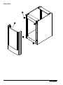
4. Attach dispenser to base stand with supplied hardware (Fig. 5).
NOTICE!
If installing optional Drip Tray Drain Kit, refer to instructions
included with the Drip Tray Drain Kit.
Fig. 5
5. Connect water line. Recommended routing (Fig. 6) allows easy access
to water for cleaning and sanitizing procedure.
6. If installing the optional internal water lter*, please see Optional
Internal Water Filter Installation on page 11 before proceeding.
If not, proceed to step 7.
* If your dispenser has the internal water lter option, the water lter must
be installed for the dispenser to operate. Because internal components
will need to be accessed for both procedures, Follett recommends
installing the water lter just prior to initial sanitizing.
7. Connect power supply.
8. Sanitize the dispenser prior to use (see the Initial Sanitizing Kit
instructions shipped with this unit).
Fig. 6
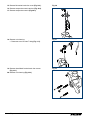
9. Secure unit to wall or cove molding with supplied bracket (Fig. 7) to
prevent tipping.
Note: Fasteners must be supplied by installer.
WARNING!
Freestanding unit must be secured to wall to prevent tipping.
Failure to do could result in personal injury or damage to the
unit.
Fig. 7
X4
91.4 cm (3')
1/4" MPT
Plug
Valve

Dispenser and Ice Machine 230 V/50 Hz and 220 V/60 Hz 11
Optional Leg Accessory Installation
1. If installing optional 6" Leg Accessory (item# 00956318), tilt or lay
base stand on side and screw each leg into stand (Fig.8).
Fig. 8
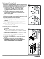
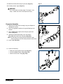
Optional Internal Water Filter Installation
If your dispenser has the internal water lter option, the water lter must be
installed for the dispenser to operate. Because internal components will need
to be accessed for both procedures, Follett recommends installing the water
lter just prior to initial sanitizing.
1. If installing the optional internal water lter, please complete the
steps shown in Accessing Internal Components on page 12
before proceeding.
2. Lift and remove the top panel, set aside (Fig. 9.1).
3. Remove two screws (Fig. 9.2) and remove left side panel.
4. Install lter as shown. Turn lter clockwise until it is fully seated
(Fig.9.3).
Fig. 9
1
2
3

12 Dispenser and Ice Machine 230 V/50 Hz and 220 V/60 Hz
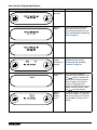
Maintenance/Cleaning Mode
Cleaning Mode (Dispensing Disabled) - Use when cleaning surface
Entering Cleaning Mode disables the User Interface and allows you to clean
the outside of the dispenser without accidentally dispensing water or ice.
1. To enter Cleaning Mode, press and immediately release the
maintenance/clean switch (Fig. 10.1) so that only "FRESH
FILTERED ICE AND WATER" displays in the user interface
(Fig.10.2).
2. To exit Cleaning Mode, press and immediately release the
maintenance/clean switch so that the ice and water icons also
display in the user interface.
Maintenance Mode (All Operations Disabled) - Use when cleaning ice
machine
Entering Maintenance Mode disables all operations and allows you to safely
clean and/or sanitize the ice machine and dispenser.
1. To enter Maintenance Mode, press and hold the maintenance/
clean switch (Fig. 10.3) until displays in the user interface
(Fig.10.4).
2. To exit Maintenance Mode, press and hold the maintenance/clean
switch until
no longer displays in the user interface.
Note: Entering and exiting Maintenance Mode will reset the six-month
periodic maintenance reminder.
Fig. 10
4
3
2
1
Accessing Internal Components
CAUTION!
Except for routine cleaning and sanitizing, only qualied
technicians should attempt to service or maintain this equipment.
1. Press and hold the maintenance/clean switch (Fig. 10.1) until
displays in the user interface (Fig. 10.2).
2. Remove (unscrew) chrome ice dispenser chute (Fig. 11.1).
3. Remove the drip tray (Fig. 11.2).
4. Remove the two screws (Fig. 11.3) on the front panel (behind the
drip tray).
5. Remove and set aside the front panel (Fig. 11.4). Do not
disengage the plug on the back of the User Interface or the
tubing at the water dispenser chute (if so equipped).
Fig. 11
1
2
3
4

Dispenser and Ice Machine 230 V/50 Hz and 220 V/60 Hz 13
Filter Display Indicator Activation
If you purchased your dispenser with a Follett lter, the lter display indicator
activation has been preset at the factory.
If you are using an “after market lter,” an adjustment may be made to
activate the “Fresh Filtered Ice & Water” display.
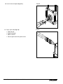
Activating “Fresh Filtered Ice & Water”
1. Remove the front panel as explained in Accessing Internal
Components on page 12 then refer to Fig. 12.
2. Remove top panel (Fig. 12.1).
Note: For _15 Series dispensers, the right side panel must also be
removed.
3. Remove (1) screw and top of control board enclosure (Fig. 12.2).
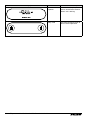
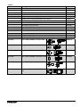
4. Locate the DIP switches on the dispenser's control board (Fig. 13).
Use a ne-pointed object to move the “Filter” DIP switch (DIP switch
#3) to the ON position.
Deactivating the Six-Month Maintenance/Filter Change Reminder
1. Use a ne-pointed object to move the “PM” DIP switch (DIP switch
#8) to the ON position.
Fig. 12
1
2
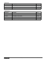
Ice and water
Internal filter supplied or to display "Fresh Filtered"
30 minute delay
Six-month PM disabled
OFF ON
Not used (OFF position)
Ice only
No internal filter
Not used (OFF position)
Not used (OFF position)
15 minute delay
Not used (OFF position)
Six-month PM enabled
1 2 3 4 5 6 7 8
Fig. 13

14 Dispenser and Ice Machine 230 V/50 Hz and 220 V/60 Hz
Cleaning and Sanitizing Procedure
Cleaning and sanitizing should be performed at least every 6 months (more often
if local water conditions dictate).
WARNING!
§ Place the dispenser in Maintenance Mode prior to servicing or
cleaning the ice machine. See Maintenance/Cleaning Mode on
page 12.
§ For protection, rubber gloves and safety goggles (and/or face shield)
should be worn when handling SafeCLEAN Plus™.
§ Do not use bleach, it will damage the dispenser.
Required Supplies
§ 7 Series
: Follow the directions on the SafeCLEAN Plus packaging to mix
3 gal (11.4 L) of Follett SafeCLEAN Plus solution. Use 100 F (38 C) water.
15 Series
: Follow the directions on the SafeCLEAN Plus packaging to mix
6 gal (22.7 L) of Follett SafeCLEAN Plus solution. Use 100 F (38 C) water.
§ Funnel, bucket,
100 F (38 C
) potable water
Ice machine and Dispenser
1. Dispense all the ice out of the unit.
2. Press and hold maintenance/clean switch until
displays in the user
interface to enter Maintenance Mode.
3. Remove (unscrew) chrome ice dispense chute (Fig. 14.1).
4. Remove drip tray (Fig. 14.2).
5. Remove (2) screws located behind the drip tray (Fig. 14.3).
6. Move front panel and place on top or beside unit (Fig. 14.4).
7. Remove plug cap from the end of drain tube (Fig. 14.5) and lower tube
to drain water into bucket. After the system has been drained of water
replace plug cap in drain tube.
8. Secure tube in holder.
9. Remove cap from bin lid cover (Fig. 14.6).
10. Screw bin lid cover cap onto ice discharge chute (Fig. 14.7).
Fig. 14
1
2
3
4
6
5
7
11. Pour SafeCLEAN Plus solution into bin lid access spout until solution reaches the spout neck.
12. Allow the SafeCLEAN Plus solution to remain in unit for 15 minutes.
13. While machine is cleaning, remove top and right side panel to access and clean air-cooled condenser.
14. Submerge ice dispense chute in the remainder of SafeCLEAN Plus solution for 2 minutes. Rinse with
clean, potable water.
15. Drain system by lowering drain tube into bucket.
16. Secure drain tube into holder.
1 7. Fill and drain twice with potable water. Secure drain tube.
18. Place a bucket under the dispense chute and remove cap. Note: Some SafeCLEAN Plus solution will
remain and drain out when cap is removed. Reposition cap on bin lid spout.
19. Reinstall front panel, ice dispense chute, and drip tray.
20. Press and hold maintenance/clean switch to exit Maintenance Mode.

Dispenser and Ice Machine 230 V/50 Hz and 220 V/60 Hz 15
User Interface and Exterior Cabinet
1. Press and release maintenance/clean switch so that only "FRESH FILTERED ICE AND WATER" displays
in the user interface to enter Cleaning Mode (and disable dispensing).
2. Plastic parts, including the user interface, can be cleaned with a non-abrasive glass cleaner. Clean
stainless steel panels with stainless steel cleaner.
3. Press and release maintenance/clean switch to put unit back into service.
Service
LED Indicator Description
The LED Indicator is located behind the front panel.
Fig. 15
Clean
PM
Drip tray
Water leak
HI press
HI amps
Service
Maint
Low water
Time delay
Sleep cycle
Making ice
Low bin
Power ON
LED Name LED Color Description
Clean Green The dispenser is in Cleaning Mode. Dispenser is disabled to allow for cleaning of
front panel. See Maintenance/Cleaning Mode on page 12.
— N/A Not used.
PM Red Six-month periodic maintenance required.
Drip tray Red Drip tray full.
Water leak Red Internal leak in dispenser.
High amps Red Auger gearmotor has exceeded 0.55A. The HI amps and Time delay LEDs will
illuminate, the machine will shut down for one hour, the LEDs will turn off, and the
machine will resume normal operation.
Service Red 8000 hour bushing check (call Follett technical service group at (877) 612-5086 or
+1 (610) 252-7301).
Maintenance Yellow Enter Maintenance Mode by pressing and holding maintenance/clean switch for 5
seconds. Unit will not make or dispense ice.
Low water Yellow Insufficient water supply to machine or no low bin LED upon startup.
Time delay Yellow Ice production will not resume for at least 15 minutes after a full bin is achieved and
a minimum amount of dispense activity has elapsed.
Sleep cycle Green After a full bin and 10 minutes of non-use, the unit goes into standby and will not
produce ice until either:
_7 Series:12 hours has elapsed, _15 Series: 4 hours has elapsed or ice or water
has dispensed.
Making ice Green Gearmotor, compressor, and fan motor energized.
Low bin Green Bin switch closed calling for ice.
Power on Green Power supplied to unit.

16 Dispenser and Ice Machine 230 V/50 Hz and 220 V/60 Hz
Evaporator Disassembly
1. Disconnect power from the dispenser.
2. Turn off water supply to dispenser.
3. Remove (unscrew) chrome ice dispenser chute
(Fig.16.1).
4. Remove the drip tray (Fig. 16.2).
5. Remove the two screws (Fig. 16.3) on the front panel
(behind the drip tray).
6. Remove and set aside the front panel (Fig. 16.4) - do not
disengage the plug on the back of the User Interface.
7. Lift and remove the top panel, set aside (Fig.16.5).
8. Remove two screws (Fig. 16.6) and remove left side
panel.
9. Remove two screws (Fig. 16.7) and remove right side
panel.
Fig. 16
2
1
3
4
5
6
2
1
7

Dispenser and Ice Machine 230 V/50 Hz and 220 V/60 Hz 17
10. Unplug the gear motor (three connectors) (Fig.16).
11. Remove ground screw connection.
Fig. 17
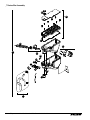
12. Remove gear motor:
§ Remove M6 allen screw, retainer, spacer and key (Fig. 18.1).
§ Remove two M6x90 allen screws (Fig. 18.2).
§ Pull gear motor from auger (Fig. 18.3).
§ Remove main housing insulation (Fig. 18.4).
13. Remove all traces of Petrol-gel from auger shaft.
Fig. 18
2
2
1
3
4
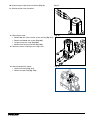
14. Remove compression nozzle:
§ Loosen hose clamp (Fig.19.1).
§ Remove transport tube (Fig. 19.2).
Fig. 19
1
2

18 Dispenser and Ice Machine 230 V/50 Hz and 220 V/60 Hz
15. Remove M6 socket head allen screw (Fig.20.1).
16. Remove compression nozzle retainer (Fig. 20.2).
1 7. Remove compression nozzle (Fig. 20.3).
Fig. 20
2
1
3
18. Remove main housing:
§ Disconnect vent line from T tting (Fig.21.1).
Fig. 21
1
19. Remove three M6x25 socket head allen screws
(Fig.22.1).
20. Remove main housing (Fig. 22.2).
Fig. 22
1
2

Dispenser and Ice Machine 230 V/50 Hz and 220 V/60 Hz 19
2 1. Remove and discard mating ring and seal (Fig.23.1).
22. Carefully remove auger (Fig. 23.2).
WARNING!
Use caution when removing auger. The auger is very
sharp - handle with care to avoid personal injury.
Fig. 23
1
2
Evaporator Assembly
1. Remove and inspect main housing O-ring seal. Replace if
damaged in any way.
2. Clean O-ring groove. Lubricate O-ring with Petrol-gel and
reinstall.
3. Use cardboard disc to press new mating ring into main
housing (Fig. 24.1).
4. Lube the shaft with liquid soap in the area shown
(Fig.24.2) and slip on seal and spring (Fig. 24.3).
Note: Do not touch the sealing surfaces with bare hands.
Contact with bare skin will cause premature seal failure.
5. Install auger (Fig. 24.4).
Fig. 24
Cardboard
disc
Do NOT
touch!
1
3
4
2
6. Install main housing:
§ Slide main housing onto auger shaft (Fig.25.1).
§ Install three M6x25 allen screws (Fig.25.2).
§ Connect vent line to T tting (Fig.25.3).
Fig. 25
1
2
3

20 Dispenser and Ice Machine 230 V/50 Hz and 220 V/60 Hz
7. Install compression nozzle:
§ Remove and inspect compression nozzle O-ring seal.
Replace if damaged in any way.
§ Clean O-ring groove. Lubricate O-ring with Petrol-gel and
reinstall.
§ Install compression nozzle (Fig.26.1).
§ Install compression nozzle retainer (Fig.26.2).
§ Install M6 socket head allen screw (Fig.26.3).
Fig. 26
2
1
3
8. Install transport tube (Fig. 27.1).
9. Tighten hose clamp (Fig.27.2).
Fig. 27
1
2
10. Install gear motor:
§ Install main housing insulation (Fig.28.1).
§ Slide gear motor onto auger shaft (Fig.28.2).
§ Install two M6x90 allen screws (Fig. 28.3).
Fig. 28
3
3
2
1
Page is loading ...
Page is loading ...
Page is loading ...
Page is loading ...
Page is loading ...
Page is loading ...
Page is loading ...
Page is loading ...
Page is loading ...
Page is loading ...
Page is loading ...
Page is loading ...
Page is loading ...
Page is loading ...
Page is loading ...
Page is loading ...
Page is loading ...
Page is loading ...
Page is loading ...
Page is loading ...
Page is loading ...
Page is loading ...
Page is loading ...
Page is loading ...
Page is loading ...
Page is loading ...
Page is loading ...
Page is loading ...
-
 1
1
-
 2
2
-
 3
3
-
 4
4
-
 5
5
-
 6
6
-
 7
7
-
 8
8
-
 9
9
-
 10
10
-
 11
11
-
 12
12
-
 13
13
-
 14
14
-
 15
15
-
 16
16
-
 17
17
-
 18
18
-
 19
19
-
 20
20
-
 21
21
-
 22
22
-
 23
23
-
 24
24
-
 25
25
-
 26
26
-
 27
27
-
 28
28
-
 29
29
-
 30
30
-
 31
31
-
 32
32
-
 33
33
-
 34
34
-
 35
35
-
 36
36
-
 37
37
-
 38
38
-
 39
39
-
 40
40
-
 41
41
-
 42
42
-
 43
43
-
 44
44
-
 45
45
-
 46
46
-
 47
47
-
 48
48


Follett chewblet 7FS100A Installation, Operation And Service Manual
- Category
- Ice cube makers
- Type
- Installation, Operation And Service Manual
- This manual is also suitable for
Ask a question and I''ll find the answer in the document
Finding information in a document is now easier with AI
Related papers
-
Follett chewblet 15CI100A Installation, Operation And Service Manual
-
Follett CVU300 Series Installation, Operation And Service Manual
-
Follett 7UD100A Installation, Operation And Service Manual
-
-
-
-
-
-
-
Follett CVU155N Series Installation, Operation And Service Manual
Other documents
-
LG GR-P227GF User manual
-
Diamond ICE25A Installation, Use And Maintenance Manual
-
 kbice FDFM1JA01 User guide
-
ASI 0363 Installation guide
-
Groupe Brandt SL3321X Owner's manual
-
Groupe Brandt SF35752 Owner's manual
-
CableWholesale 10W1-17206 Datasheet
-
Groupe Brandt FFJ1670XW Owner's manual
-
Groupe Brandt D3120 Owner's manual
-
