Mitsubishi Electric FR-A860 (600V CLASS Owner's manual
- Category
- Power adapters & inverters
- Type
- Owner's manual

INVERTER
INVERTER FR-A800
FR-A860 INSTRUCTION MANUAL (DETAILED)
D
INTRODUCTION
1
INSTALLATION AND WIRING
2
PRECAUTIONS FOR USE OF
THE INVERTER
3
BASIC OPERATION
4
PARAMETERS
5
PROTECTIVE FUNCTIONS
6
PRECAUTIONS FOR
MAINTENANCE AND
INSPECTION
7
SPECIFICATIONS
8
HEAD OFFICE: TOKYO BUILDING 2-7-3, MARUNOUCHI, CHIYODA-KU, TOKYO 100-8310, JAPAN
IB(NA)-0600563ENG-D(1903)MEE Printed in Japan Specifications subject to change without notice.
FR-A800
FR-A860 (600V CLASS SPECIFICATION INVERTER)
INSTRUCTION MANUAL (DETAILED)
FR-A860-00027 to 00450-N6
FR-A860-00680 to 04420
High functionality and high performance
MODEL
FR-A800
INSTRUCTION MANUAL
MODEL
CODE
XXX-XXX

Safety Instructions
1
Thank you for choosing this Mitsubishi Electric inverter.
This Instruction Manual provides instructions for advanced use of the FR-A860 series inverters.
Incorrect handling might cause an unexpected fault. Before using this inverter, always carefully read this Instruction Manual and
the Instruction Manual (Startup) [IB-0600562ENG] packed with the product to use the equipment to its optimum performance.
Electric Shock Prevention
Fire Prevention
Injury Prevention
Additional Instructions
The following instructions must be also followed. If the product
is handled incorrectly, it may cause unexpected fault, an injury,
or an electric shock.
Safety Instructions
Do not attempt to install, operate, maintain or inspect the
product until you have read through this Instruction Manual
and appended documents carefully and can use the
equipment correctly. Do not use this product until you have a
full knowledge of the equipment, safety information and
instructions.
Installation, operation, maintenance and inspection must be
performed by qualified personnel. Here, an expert means a
person who meets all the conditions below.
• A person who took a proper engineering training. Such
training may be available at your local Mitsubishi Electric
office. Contact your local sales office for schedules and
locations.
• A person who can access operating manuals for the
protective devices (e.g. light curtain) connected to the safety
control system. A person who has read and familiarized
himself/herself with the manuals.
In this Instruction Manual, the safety instruction levels are
classified into "WARNING" and "CAUTION"
Incorrect handling may cause
hazardous conditions, resulting in
death or severe injury.
Incorrect handling may cause
hazardous conditions, resulting in
medium or slight injury, or may cause
only material damage.
Note that even the level may lead to a
serious consequence depending on conditions. Be sure to
follow the instructions of both levels as they are critical to
personnel safety.
WARNING
While the inverter power is ON, do not remove the front cover or
the wiring cover. Do not run the inverter with the front cover or
the wiring cover removed, as accidental contact with exposed
high-voltage terminals and internal components may occur,
resulting in an electrical shock.
Even if power is OFF, do not remove the front cover except for
wiring or periodic inspection. You may accidentally touch the
charged inverter circuits and get an electric shock.
Before wiring or inspection, the power lamp must be switched
OFF. Any person who is involved in wiring or inspection shall
wait for at least 10 minutes after the power supply has been
switched OFF and check that there are no residual voltage using
a tester or the like. The capacitor is charged with high voltage for
some time after power OFF, and it is dangerous.
This inverter must be earthed (grounded). Earthing (grounding)
must conform to the requirements of national and local safety
regulations and electrical code (NEC section 250, IEC 61140
class 1 and other applicable standards).
Any person who is involved in wiring or inspection of this
equipment shall be fully competent to do the work.
The inverter must be installed before wiring. Otherwise you may
get an electric shock or be injured.
Setting dial and key operations must be performed with dry
hands to prevent an electric shock. Otherwise you may get an
electric shock.
Do not subject the cables to scratches, excessive stress, heavy
loads or pinching. Doing so may cause an electric shock.
Do not change the cooling fan while power is ON. It is dangerous
to change the cooling fan while power is ON.
Do not touch the printed circuit board or handle the cables with
wet hands. Doing so may cause an electric shock.
When measuring the main circuit capacitor capacity, the DC
voltage is applied to the motor for 1s at powering OFF. Never
touch the motor terminal, etc. right after powering OFF to
prevent an electric shock.
A PM motor is a synchronous motor with high-performance
magnets embedded in the rotor. Motor terminals holds high-
voltage while the motor is running even after the inverter power
is turned OFF. Before wiring or inspection, the motor must be
confirmed to be stopped. In an application, such as fan and
blower, where the motor is driven by the load, a low-voltage
manual motor starter must be connected at the inverter's output
side, and wiring and inspection must be performed while the
motor starter is open. Otherwise you may get an electric shock.
WARNING
CAUTION
CAUTION
CAUTION
Inverter must be installed on a nonflammable wall without holes
(so that nobody touches the inverter heat sink on the rear side,
etc.). Mounting it to or near flammable material may cause a fire.
If the inverter has become faulty, the inverter power must be
switched OFF. A continuous flow of large current may cause a
fire.
When using a brake resistor, a sequence that will turn OFF
power when a fault signal is output must be configured.
Otherwise the brake resistor may excessively overheat due to
damage of the brake transistor and such, causing a fire.
Do not connect a resistor directly to the DC terminals P/+ and N/
-. Doing so could cause a fire.
Be sure to perform daily and periodic inspections as specified in
the Instruction Manual. If a product is used without any
inspection, a burst, breakage, or a fire may occur.
CAUTION
The voltage applied to each terminal must be the ones specified
in the Instruction Manual. Otherwise an explosion or damage
may occur.
The cables must be connected to the correct terminals.
Otherwise an explosion or damage may occur.
The polarity (+ and -) must be correct. Otherwise burst, damage,
etc. may occur.
While power is ON or for some time after power-OFF, do not
touch the inverter as it will be extremely hot. Touching these
devices may cause a burn.
CAUTION
Transportation and installation
Any person who is opening a package using a sharp object,
such as a knife and cutter, must wear gloves to prevent injuries
caused by the edge of the sharp object.
The product must be transported in correct method that
corresponds to the weight. Failure to do so may lead to injuries.
Do not stand or rest heavy objects on the product.
Do not stack the boxes containing inverters higher than the
number recommended.
When carrying the inverter, do not hold it by the front cover; it
may fall off or fail.
During installation, caution must be taken not to drop the inverter
as doing so may cause injuries.
The product must be installed on the surface that withstands the
weight of the inverter.
Do not install the product on a hot surface.
The mounting orientation of the inverter must be correct.
The inverter must be installed on a strong surface securely with
screws so that it will not drop.
Do not install or operate the inverter if it is damaged or has parts
missing.
Foreign conductive objects must be prevented from entering the
inverter. That includes screws and metal fragments or other
flammable substance such as oil.
As the inverter is a precision instrument, do not drop or subject it
to impact.
For the FR-A860-00090 or lower, the surrounding air temperature
must be -10 to +40°C for the LD, ND, or HD rating (-10 to +30°C
for the SLD rating) (non-freezing). Otherwise the inverter may be
damaged.
For the FR-A860-00170 to 01080, the surrounding air
temperature must be -10 to +40°C (non-freezing). Otherwise the
inverter may be damaged.
For the FR-A860-01440 or higher, the surrounding air
temperature must be -10 to +50°C for the LD or ND rating (-10 to
+40°C for the SLD or HD rating) (non-freezing). Otherwise the
inverter may be damaged.
The ambient humidity must be 95%RH or less (non-
condensing). Otherwise the inverter may be damaged. (Refer to
page 24 for details.)

2
Safety Instructions
2.9 m/s
2
or less for the FR-A860-02890 or higher.
CAUTION
Transportation and Mounting
The storage temperature (applicable for a short time, e.g. during
transit) must be between -20 and +65°C. Otherwise the inverter
may be damaged.
The inverter must be used indoors (without corrosive gas,
flammable gas, oil mist, dust and dirt etc.) Otherwise the inverter
may be damaged.
The inverter must be used at an altitude of 2500 m or less, with
5.9 m/s
2
or less vibration at 10 to 55 Hz (directions of X, Y, Z
axes). Otherwise the inverter may be damaged. (For the
installation at an altitude above 1000 m, consider a 3% reduction
in the rated current per 500 m increase in altitude.)
If halogen-based materials (fluorine, chlorine, bromine, iodine,
etc.) infiltrate into a Mitsubishi Electric product, the product will
be damaged. Halogen-based materials are often included in
fumigant, which is used to sterilize or disinfest wooden
packages. When packaging, prevent residual fumigant
components from being infiltrated into Mitsubishi Electric
products, or use an alternative sterilization or disinfection
method (heat disinfection, etc.) for packaging. Sterilization of
disinfection of wooden package should also be performed before
packaging the product.
Wiring
Do not install a power factor correction capacitor or surge
suppressor/capacitor type filter on the inverter output side.
These devices on the inverter output side may be overheated or
burn out.
The output side terminals (terminals U, V, and W) must be
connected correctly. Otherwise the motor will rotate inversely.
PM motor terminals (U, V, W) hold high-voltage while the PM
motor is running even after the power is turned OFF. Before
wiring, the PM motor must be confirmed to be stopped.
Otherwise you may get an electric shock.
Never connect an PM motor to the commercial power supply.
Applying the commercial power supply to input terminals (U, V,
W) of an PM motor will burn the PM motor. The PM motor must
be connected with the output terminals (U, V, W) of the inverter.
Trial run
Before starting operation, each parameter must be confirmed
and adjusted. A failure to do so may cause some machines to
make unexpected motions.
WARNING
Usage
Stay away from the equipment after using the retry function in
this product as the equipment will restart suddenly after the
output shutoff of this product.
Since pressing the STOP/RESET key may not stop output
depending on the function setting status, separate circuit and
switch that make an emergency stop (power OFF, mechanical
brake operation for emergency stop, etc.) must be provided.
OFF status of the start signal must be confirmed before resetting
the inverter fault. Resetting inverter fault with the start signal ON
restarts the motor suddenly.
Do not use an PM motor for an application where the PM motor
is driven by its load and runs at a speed higher than the
maximum motor speed.
Use this inverter only with three-phase induction motors or with
an PM motor. Connection of any other electrical equipment to
the inverter output may damage the equipment.
Performing pre-excitation (LX signal and X13 signal) under
torque control (Real sensorless vector control) may start the
motor running at a low speed even when the start command
(STF or STR) is not input The motor may run also at a low speed
when the speed limit value = 0 with a start command input. It
must be confirmed that the motor running will not cause any
safety problem before performing pre-excitation.
Do not modify the equipment.
Do not perform parts removal which is not instructed in this
manual. Doing so may lead to fault or damage of the product.
CAUTION
Usage
The electronic thermal relay function does not guarantee
protection of the motor from overheating. It is recommended to
install both an external thermal and PTC thermistor for overheat
protection.
Do not use a magnetic contactor on the inverter input for
frequent starting/stopping of the inverter. Doing so may shorten
the life of this product.
The effect of electromagnetic interference must be reduced by
using a noise filter or by other means. Otherwise nearby
electronic equipment may be affected.
Appropriate measures must be taken to suppress harmonics.
Otherwise power supply harmonics from the inverter may heat/
damage the power factor correction capacitor and generator.
When driving a 600 V class motor by the inverter, the motor must
be an insulation-enhanced motor or measures must be taken to
suppress surge voltage. Surge voltage attributable to the wiring
constants may occur at the motor terminals, deteriorating the
insulation of the motor.
When parameter clear or all parameter clear is performed, the
required parameters must be set again before starting
operations. because all parameters return to their initial values.
The inverter can be easily set for high-speed operation. Before
changing its setting, the performances of the motor and machine
must be fully examined.
Stop status cannot be hold by the inverter's brake function. In
addition to the inverter’s brake function, a holding device must
be installed to ensure safety.
Before running an inverter which had been stored for a long
period, inspection and test operation must be performed.
Static electricity in your body must be discharged before you
touch the product.
Only one PM motor can be connected to an inverter.
An PM motor must be used under PM sensorless vector control.
Do not use a synchronous motor, induction motor, or
synchronous induction motor.
Do not connect an PM motor in the induction motor control
settings (initial settings). Do not use an induction motor in the
PM sensorless vector control settings. It will cause a failure.
In the system with an PM motor, the inverter power must be
turned ON before closing the contacts of the contactor at the
output side.
Emergency stop
A safety backup such as an emergency brake must be provided
for devices or equipment in a system to prevent hazardous
conditions in case of failure of this product or an external device
controlling this product.
When the breaker on the inverter input side trips, the wiring must
be checked for fault (short circuit), and internal parts of the
inverter for a damage, etc. The cause of the trip must be
identified and removed before turning ON the power of the
breaker.
When a protective function is activated, take an appropriate
corrective action, then reset the inverter, and resume the
operation.
Maintenance, inspection and parts replacement
Do not carry out a megger (insulation resistance) test on the
control circuit of the inverter. It will cause a failure.
Disposal
The inverter must be treated as industrial waste.
General instruction
For clarity, illustrations in this Instruction Manual may be drawn
with covers or safety guards removed. Ensure all covers and
safety guards are properly installed prior to starting operation.
For details on the PM motor, refer to the Instruction Manual of
the PM motor.

CONTENTS
3
1 INTRODUCTION 11
1.1 Product checking and accessories 12
1.2 Component names 13
1.3 Operation steps 14
1.4 About the related manuals 15
2 INSTALLATION AND WIRING 17
2.1 Peripheral devices 18
2.1.1 Inverter and peripheral devices ......................................................................................................................18
2.1.2 Peripheral devices ..........................................................................................................................................20
2.2 Removal and reinstallation of the front covers 21
2.3 Installation of the inverter and enclosure design 24
2.3.1 Inverter installation environment.....................................................................................................................24
2.3.2 Amount of heat generated by the inverter ......................................................................................................26
2.3.3 Cooling system types for inverter enclosure...................................................................................................27
2.3.4 Inverter installation..........................................................................................................................................28
2.3.5 Protruding the heat sink through a panel........................................................................................................30
2.4 Terminal connection diagrams 32
2.5 Main circuit terminals 34
2.5.1 Details on the main circuit terminals ...............................................................................................................34
2.5.2 Terminal layout of the main circuit terminals, wiring of power supply and the motor......................................35
2.5.3 Applicable cables and the wiring length..........................................................................................................40
2.5.4 Earthing (grounding) precautions ...................................................................................................................42
2.6 Control circuit 43
2.6.1 Details on the control circuit terminals............................................................................................................43
2.6.2 Control logic (sink/source) change .................................................................................................................47
2.6.3 Wiring of control circuit ...................................................................................................................................49
2.6.4 Wiring precautions..........................................................................................................................................51
2.6.5 When using separate power supplies for the control circuit and the main circuit ...........................................52
2.6.6 When supplying 24 V external power to the control circuit .............................................................................54
2.7 Communication connectors and terminals 56
2.7.1 PU connector..................................................................................................................................................56
2.7.2 USB connector................................................................................................................................................58
2.7.3 RS-485 terminal block ....................................................................................................................................59
2.8 Connection of motor with encoder (vector control) 60
2.9 Parameter settings for a motor with encoder 64
2.10 Connection of stand-alone option units 65
2.10.1 Connection of the brake resistor other than the provided brake resistor........................................................65
2.10.2 Connection of the DC reactor .........................................................................................................................66
CONTENTS

4
CONTENTS
3 PRECAUTIONS FOR USE OF THE INVERTER 67
3.1 Electro-magnetic interference (EMI) and leakage currents 68
3.1.1 Leakage currents and countermeasures........................................................................................................ 68
3.1.2 Countermeasures against inverter-generated EMI ........................................................................................ 69
3.2 Power supply harmonics 71
3.3 Installation of a reactor 71
3.4 Power-OFF and magnetic contactor (MC) 72
3.5 Countermeasures against deterioration of the 600 V class motor insulation 73
3.6 Checklist before starting operation 74
3.7 Failsafe system which uses the inverter 76
4 BASIC OPERATION 79
4.1 Frequently-used parameters (simple mode parameters) 80
4.1.1 Simple mode parameter list............................................................................................................................ 80
4.2 Basic operation procedure (PU operation) 82
4.2.1 Operating at a set frequency (example: operating at 30 Hz).......................................................................... 82
4.2.2 Setting the frequency by switches (multi-speed setting) ................................................................................ 83
4.2.3 Setting the frequency with analog signals (voltage input) .............................................................................. 84
4.2.4 Using an analog signal (current input) to give a frequency command ........................................................... 85
4.3 Basic operation procedure (External operation) 86
4.3.1 Using the frequency set by the operation panel ............................................................................................. 86
4.3.2 Setting the frequency by switches (multi-speed setting) (Pr.4 to Pr.6)........................................................... 87
4.3.3 Setting the frequency with analog signals (voltage input) .............................................................................. 88
4.3.4 Changing the frequency (60 Hz, initial value) at the maximum voltage input (5 V, initial value) .................... 89
4.3.5 Using an analog signal (current input) to give a frequency command ........................................................... 90
4.3.6 Changing the frequency (60 Hz, initial value) at the maximum current input (at 20 mA, initial value) ........... 91
4.4 Basic operation procedure (JOG operation) 92
4.4.1 Performing JOG operation using external signals.......................................................................................... 92
4.4.2 JOG operation from the operation panel........................................................................................................ 93
5 PARAMETERS 95
5.1 Parameter List 96
5.1.1 Parameter list (by parameter number) ........................................................................................................... 96
5.1.2 Parameter list (by function group) ................................................................................................................ 122
5.2 Control method 131
5.2.1 Vector control and Real sensorless vector control ....................................................................................... 134
5.2.2 Changing the control method ....................................................................................................................... 137
5.2.3 Selecting the Advanced magnetic flux vector control .................................................................................. 143
5.2.4 Selecting the PM sensorless vector control ................................................................................................ 145

CONTENTS
5
5.3 Speed control under Real sensorless vector control, vector control, PM sensorless vector
control 147
5.3.1 Setting procedure of Real sensorless vector control (speed control) ..........................................................150
5.3.2 Setting procedure of vector control (speed control) .....................................................................................152
5.3.3 Setting procedure of PM sensorless vector control (speed control) ............................................................153
5.3.4 Setting the torque limit level .........................................................................................................................154
5.3.5 Performing high-accuracy, fast-response control (gain adjustment for Real sensorless vector control, vector
control and PM sensorless vector control) ...................................................................................................164
5.3.6 Troubleshooting in the speed control ...........................................................................................................171
5.3.7 Speed feed forward control and model adaptive speed control ...................................................................173
5.3.8 Torque bias ..................................................................................................................................................175
5.3.9 Avoiding motor overrunning .........................................................................................................................179
5.3.10 Notch filter ....................................................................................................................................................181
5.4 Torque control under Real sensorless vector control and vector control 182
5.4.1 Torque control...............................................................................................................................................182
5.4.2 Setting procedure of Real sensorless vector control (torque control) ..........................................................187
5.4.3 Setting procedure for vector control (torque control) ...................................................................................189
5.4.4 Torque command .........................................................................................................................................190
5.4.5 Speed limit ...................................................................................................................................................195
5.4.6 Torque control gain adjustment ...................................................................................................................201
5.4.7 Troubleshooting in torque control ................................................................................................................202
5.4.8 Torque control by variable-current limiter control ........................................................................................203
5.5 Position control under vector control 204
5.5.1 About position control ..................................................................................................................................204
5.5.2 Setting procedure of vector control (position control) ..................................................................................206
5.5.3 Simple positioning function by parameters ..................................................................................................207
5.5.4 Position control by the FR-A8AL pulse train input .......................................................................................222
5.5.5 Position control by inverter pulse train input ................................................................................................225
5.5.6 Clear signal selection....................................................................................................................................226
5.5.7 Pulse monitor ...............................................................................................................................................227
5.5.8 Electronic gear setting .................................................................................................................................232
5.5.9 Position adjustment parameter settings .......................................................................................................234
5.5.10 Position control gain adjustment ..................................................................................................................236
5.5.11 Troubleshooting in position control ..............................................................................................................237
5.6 Real sensorless vector control, vector control, PM sensorless vector control adjustment 239
5.6.1 Speed detection filter and torque detection filter .........................................................................................239
5.6.2 Excitation ratio .............................................................................................................................................240
5.6.3 Gain adjustment of current controllers for the d axis and the q axis ............................................................240
5.7 (E) Environment setting parameters 241
5.7.1 Real time clock function................................................................................................................................242
5.7.2 Reset selection/disconnected PU detection/PU stop selection ....................................................................244
5.7.3 PU display language selection......................................................................................................................247
5.7.4 Buzzer control...............................................................................................................................................247
5.7.5 PU contrast adjustment ................................................................................................................................248
5.7.6 Extended direct setting .................................................................................................................................248
5.7.7 Resetting USB host errors ............................................................................................................................249
5.7.8 Multiple rating setting....................................................................................................................................249
5.7.9 Parameter write selection .............................................................................................................................251
5.7.10 Password function ........................................................................................................................................253
5.7.11 Free parameter .............................................................................................................................................255
5.7.12 Setting multiple parameters as a batch ........................................................................................................255
5.7.13 Extended parameter display and user group function ..................................................................................259
5.7.14 Parameter copy alarm release......................................................................................................................260
5.7.15 PWM carrier frequency and Soft-PWM control.............................................................................................261
5.7.16 Inverter parts life display...............................................................................................................................262

6
CONTENTS
5.7.17 Maintenance timer alarm.............................................................................................................................. 266
5.7.18 Current average value monitor signal .......................................................................................................... 267
5.8 (F) Setting of acceleration/deceleration time and acceleration/deceleration pattern 269
5.8.1 Setting the acceleration and deceleration time ............................................................................................ 269
5.8.2 Acceleration/deceleration pattern................................................................................................................. 274
5.8.3 Remote setting function................................................................................................................................ 279
5.8.4 Starting frequency and start-time hold function ........................................................................................... 283
5.8.5 Minimum motor speed frequency ................................................................................................................ 284
5.8.6 Shortest acceleration/deceleration and optimum acceleration/deceleration (automatic acceleration/
deceleration)................................................................................................................................................. 285
5.8.7 Lift operation (automatic acceleration/deceleration) .................................................................................... 288
5.9 (D) Operation command and frequency command 290
5.9.1 Operation mode selection ............................................................................................................................ 291
5.9.2 Startup in Network operation mode at power-ON ........................................................................................ 300
5.9.3 Start command source and frequency command source during communication operation......................... 301
5.9.4 Reverse rotation prevention selection .......................................................................................................... 308
5.9.5 Frequency setting via pulse train input......................................................................................................... 308
5.9.6 JOG operation.............................................................................................................................................. 312
5.9.7 Operation by multi-speed setting.................................................................................................................. 314
5.10 (H) Protective function parameter 316
5.10.1 Motor overheat protection (electronic thermal O/L relay) ............................................................................. 317
5.10.2 Fault definition .............................................................................................................................................. 323
5.10.3 Cooling fan operation selection .................................................................................................................... 324
5.10.4 Earth (ground) fault detection at start .......................................................................................................... 325
5.10.5 Initiating a protective function....................................................................................................................... 325
5.10.6 I/O phase loss protection selection .............................................................................................................. 326
5.10.7 Retry function ............................................................................................................................................... 327
5.10.8 Limiting the output frequency (maximum/minimum frequency).................................................................... 329
5.10.9 Avoiding the mechanical resonance points (frequency jump) ...................................................................... 330
5.10.10 Stall prevention operation ............................................................................................................................ 332
5.10.11 Load characteristics fault detection .............................................................................................................. 339
5.10.12 Motor overspeeding detection ...................................................................................................................... 343
5.11 (M) Monitor display and monitor output signal 344
5.11.1 Speed display and rotations per minute setting ........................................................................................... 345
5.11.2 Monitor indicator selection using operation panel or via communication ..................................................... 347
5.11.3 Monitor display selection for terminals FM and AM...................................................................................... 357
5.11.4 Adjustment of terminal FM and terminal AM ................................................................................................ 362
5.11.5 Energy saving monitor.................................................................................................................................. 365
5.11.6 Output terminal function selection ................................................................................................................ 370
5.11.7 Output frequency detection .......................................................................................................................... 379
5.11.8 Output current detection function ................................................................................................................. 382
5.11.9 Output torque detection ............................................................................................................................ 384
5.11.10 Remote output function ................................................................................................................................ 385
5.11.11 Analog remote output function ..................................................................................................................... 386
5.11.12 Fault code output selection .......................................................................................................................... 388
5.11.13 Pulse train output of output power................................................................................................................ 389
5.11.14 Detection of control circuit temperature........................................................................................................ 390
5.11.15 Encoder pulse dividing output ...................................................................................................................... 391
5.12 (T) Multi-Function Input Terminal Parameters 392
5.12.1 Analog input selection .................................................................................................................................. 393
5.12.2 Analog input terminal (terminal 1, 4) function assignment ........................................................................... 397
5.12.3 Analog input compensation.......................................................................................................................... 398
5.12.4 Analog input responsiveness and noise elimination..................................................................................... 400
5.12.5 Frequency setting voltage (current) bias and gain ....................................................................................... 402
5.12.6 Bias and gain for torque (magnetic flux) and set voltage (current)............................................................... 407

CONTENTS
7
5.12.7 Checking of current input on analog input terminal ......................................................................................411
5.12.8 Input terminal function selection ...................................................................................................................415
5.12.9 Inverter output shutoff signal ........................................................................................................................418
5.12.10 External fault input signal..............................................................................................................................419
5.12.11 Selecting operation condition of the second function selection signal (RT) and the third function selection
signal (X9).....................................................................................................................................................419
5.12.12 Start signal operation selection.....................................................................................................................421
5.13 (C) Motor constant parameters 423
5.13.1 Applied motor................................................................................................................................................423
5.13.2 Offline auto tuning ......................................................................................................................................426
5.13.3 Offline auto tuning for a PM motor (motor constants tuning) .......................................................................436
5.13.4 Online auto tuning ........................................................................................................................................444
5.13.5 Signal loss detection of encoder signals ......................................................................................................446
5.14 (A) Application parameters 447
5.14.1 Electronic bypass function ...........................................................................................................................448
5.14.2 Self power management ..............................................................................................................................454
5.14.3 Brake sequence function .............................................................................................................................457
5.14.4 Start count monitor .......................................................................................................................................462
5.14.5 Stop-on-contact control ................................................................................................................................463
5.14.6 Load torque high speed frequency control ...................................................................................................466
5.14.7 Traverse function..........................................................................................................................................469
5.14.8 Anti-sway control ..........................................................................................................................................471
5.14.9 Orientation control ........................................................................................................................................473
5.14.10 PID control....................................................................................................................................................488
5.14.11 Changing the display increment of the numerical values used in PID control ..............................................501
5.14.12 PID pre-charge function................................................................................................................................504
5.14.13 Dancer control ..............................................................................................................................................508
5.14.14 Automatic restart after instantaneous power failure/flying start with an induction motor .............................515
5.14.15 Offline auto tuning for a frequency search ...................................................................................................522
5.14.16 Power failure time deceleration-to-stop function...........................................................................................526
5.14.17 PLC function .................................................................................................................................................531
5.14.18 Trace function...............................................................................................................................................533
5.15 (N) Operation via communication and its settings 541
5.15.1 Wiring and configuration of PU connector ....................................................................................................541
5.15.2 Wiring and configuration of RS-485 terminals ..............................................................................................543
5.15.3 Initial setting of operation via communication...............................................................................................546
5.15.4 Initial settings and specifications of RS-485 communication........................................................................553
5.15.5 Mitsubishi inverter protocol (computer link communication) .........................................................................555
5.15.6 MODBUS RTU communication specification................................................................................................569
5.15.7 USB device communication..........................................................................................................................584
5.15.8 Automatic connection with GOT ...................................................................................................................585
5.15.9 Backup/restore..............................................................................................................................................586
5.16 (G) Control parameters 588
5.16.1 Manual torque boost ....................................................................................................................................589
5.16.2 Base frequency, voltage ..............................................................................................................................591
5.16.3 Load pattern selection .................................................................................................................................593
5.16.4 Excitation current low-speed scaling factor ..................................................................................................595
5.16.5 Energy saving control ..................................................................................................................................597
5.16.6 Adjustable 5 points V/F ................................................................................................................................598
5.16.7 DC injection brake, zero speed control, and servo lock................................................................................599
5.16.8 Output stop function......................................................................................................................................605
5.16.9 Stop selection ...............................................................................................................................................607
5.16.10 Regenerative brake selection and DC feeding mode ...................................................................................608
5.16.11 Regeneration avoidance function .................................................................................................................614
5.16.12 Increased magnetic excitation deceleration .................................................................................................617
5.16.13 Slip compensation .......................................................................................................................................618

8
CONTENTS
5.16.14 Encoder feedback control ............................................................................................................................ 619
5.16.15 Droop control ............................................................................................................................................... 621
5.16.16 Speed smoothing control ............................................................................................................................. 624
6 PROTECTIVE FUNCTIONS 625
6.1 Inverter fault and alarm indications 626
6.2 Reset method for the protective functions 626
6.3 The list of fault displays 627
6.4 Causes and corrective actions 629
6.5 Check first when you have a trouble 648
6.5.1 Motor does not start ..................................................................................................................................... 648
6.5.2 Motor or machine is making abnormal acoustic noise ................................................................................. 650
6.5.3 Inverter generates abnormal noise............................................................................................................... 650
6.5.4 Motor generates heat abnormally................................................................................................................. 651
6.5.5 Motor rotates in the opposite direction ......................................................................................................... 651
6.5.6 Speed greatly differs from the setting........................................................................................................... 651
6.5.7 Acceleration/deceleration is not smooth....................................................................................................... 652
6.5.8 Speed varies during operation ..................................................................................................................... 652
6.5.9 Operation mode is not changed properly ..................................................................................................... 653
6.5.10 Operation panel display is not operating ...................................................................................................... 653
6.5.11 Motor current is too large ............................................................................................................................. 653
6.5.12 Speed does not accelerate........................................................................................................................... 654
6.5.13 Unable to write parameter setting ................................................................................................................ 654
6.5.14 Power lamp is not lit ..................................................................................................................................... 654
7 PRECAUTIONS FOR MAINTENANCE AND
INSPECTION 655
7.1 Inspection item 656
7.1.1 Daily inspection ............................................................................................................................................ 656
7.1.2 Periodic inspection ....................................................................................................................................... 656
7.1.3 Daily and periodic inspection........................................................................................................................ 657
7.1.4 Checking the inverter module and the converter module............................................................................. 659
7.1.5 Cleaning ....................................................................................................................................................... 659
7.1.6 Replacement of parts ................................................................................................................................... 660
7.1.7 Removal and reinstallation of the control circuit terminal block.................................................................... 665
7.2 Measurement of main circuit voltages, currents and powers 666
7.2.1 Measurement of powers............................................................................................................................... 668
7.2.2 Measurement of voltages ............................................................................................................................. 668
7.2.3 Measurement of currents ............................................................................................................................. 668
7.2.4 Measurement of inverter input power factor................................................................................................. 668
7.2.5 Measurement of converter output voltage (across terminals P and N) ........................................................668
7.2.6 Measurement of inverter output frequency................................................................................................... 669
7.2.7 Insulation resistance test using megger ....................................................................................................... 669
7.2.8 Pressure test ................................................................................................................................................ 669

CONTENTS
9
8 SPECIFICATIONS 671
8.1 Inverter rating 672
8.2 Common specifications 674
8.3 Outline dimension drawings 676
8.3.1 Inverter outline dimension drawings .............................................................................................................676
APPENDIX 681
Appendix 1 For customers replacing the conventional model with this inverter................................. 682
Appendix 2 International standards.......................................................................................................... 683
Appendix 3 Specification comparison between PM sensorless vector control and induction motor
control ..................................................................................................................................... 684
Appendix 4 Parameters (functions) and instruction codes under different control methods ............ 685
Appendix 5 For customers using HMS network options ........................................................................ 704

MEMO
10

INTRODUCTION
11
1
1 INTRODUCTION
The contents described in this chapter must be read before using this
product.
Always read the instructions before using the equipment.
For the "INTRODUCTION" of the separated converter type, refer to the
FR-A862 (Separated Converter Type) Instruction Manual (Hardware) [IB-
0600571ENG]
1.1 Product checking and accessories.........................................12
1.2 Component names....................................................................13
1.3 Operation steps.........................................................................14
1.4 About the related manuals.......................................................15
<Abbreviations>
DU ..................................................Operation panel (FR-LU08)
Operation panel .............................Operation panel (FR-LU08)
Parameter unit ...............................Parameter unit (FR-PU07)
PU ..................................................Operation panel and parameter unit
Inverter ...........................................Mitsubishi Electric inverter FR-A860 series
Vector control compatible option..... FR-A8AP/FR-A8AL/FR-A8APA/FR-A8APR/FR-A8APS (plug-in option), FR-
A8TP (control terminal option)
Pr. ..................................................Parameter number (Number assigned to function)
PU operation ..................................Operation using the PU (operation panel/parameter unit)
External operation ..........................Operation using the control circuit signals
Combined operation ......................Combined operation using the PU (operation panel/parameter unit) and
External operation
<Trademarks>
• Microsoft and Visual C++ are registered trademarks of Microsoft Corporation in the United States and other
countries.
• MODBUS is a registered trademark of SCHNEIDER ELECTRIC USA, INC.
• Other company and product names herein are the trademarks and registered trademarks of their respective
owners.
<Notes on descriptions in this Instruction Manual>
• Connection diagrams in this Instruction Manual appear with the control logic of the input terminals as sink
logic, unless otherwise specified. (For the control logic, refer to page 47.)

Product checking and accessories
12
INTRODUCTION
1.1 Product checking and accessories
Unpack the product and check the rating plate and the capacity plate of the inverter to ensure that the model agrees with the
order and the product is intact.
Inverter model
• FR-A860-00450 or lower
• FR-A860-00680 or higher
Applicable for the FR-A860-00170 or higher.
Accessory
• Eyebolt for hanging the inverter
• Brake resistor (FR-A860-00090 or lower)
• Protective bush (FR-A860-00090 or lower)
How to read the SERIAL number
Capacity Eyebolt Size Quantity
FR-A860-02890, 03360 M10 2
FR-A860-04420 M12 2
Rating plate example
The SERIAL consists of one symbol, two characters indicating the production
year and month, and six characters indicating the control number. The last digit
of the production year is indicated as the Year, and the Month is indicated by 1
to 9, X (October), Y (November), or Z (December).
Symbol Year Month Control number
SERIAL
FR --A8 06 -1- N600320
Symbol Voltage class
600 V class6
Symbol Description
00027 to 00450 Inverter SLD rated current (A)
Symbol
Circuit board coating
(conforming to IEC60721-3-3 3C2/3S2)
UL Type 1
certification
Plated conductor
With WithWithoutN6
FR --A8 06 -1-00680
Symbol Voltage class
600 V class6
Symbol Description
00680 to 04420 Inverter SLD rated current (A)
Symbol
Circuit board coating
(conforming to IEC60721-3-3 3C2/3S2)
With
With
Plated conductor
With
Without
06∗1
60
60
,1387;;;;;
02'(/)5$1
287387;;;;;
6(5,$/;;;;;;;;;
0$'(,1;;;;;
Rating plate
Input rating
Output rating
SERIAL
Inverter model
Country of origin

Component names
INTRODUCTION
13
1
1.2 Component names
Component names are shown below.
Symbol Name Description
Refer to
page
(a) PU connector
Connects the operation panel or the parameter unit. This connector also
enables the RS-485 communication.
56
(b) USB A connector Connects a USB memory device. 58
(c) USB mini B connector
Connects a personal computer and enables communication with FR
Configurator2.
58
(d) RS-485 terminals Enables RS-485, MODBUS RTU communication. 59
(e)
Terminating resistor switch
(SW1)
Select whether or not to use the terminating resistor for RS-485 communication. 59
(f) Plug-in option connector 1
Connects a plug-in option or a communication option.
Instruction
Manual of
the option
(g) Plug-in option connector 2
(h) Plug-in option connector 3
(i)
Voltage/current input switch
(SW2)
Selects between voltage and current for the terminal 2 and 4 inputs. 393
(j) Control circuit terminal block Connects cables for the control circuit. 43
(k) Main circuit terminal block Connects cables for the main circuit. 34
(l) Charge lamp Stays ON while the power is supplied to the main circuit. 35
(m) Wiring cover
When conduits are installed in the knockout holes of this cover, wiring can be
passed through the conduits. (FR-A860-00450 or lower)
37
(n) Alarm lamp Turns ON when the protective function of the inverter is activated. 35
(o) Power lamp Stays ON while the power is supplied to the control circuit (R1/L11, S1/L21). 35
(p) Front cover (upper side)
Remove this cover for the installation of the product, installation of a plug-in
(communication) option, RS-485 terminal wiring, switching of the voltage/
current input switch, etc.
21
(q) Front cover (lower side) Remove this cover for wiring. 21
(r) Accessory cover Remove this cover for using the PU connector. 56
(s) Cooling fan Cools the inverter. (FR-A860-00061 or higher) 661
(t)
Switches for manufacturer
setting (SW3 and SW4)
Do not change the initial setting (OFF ).
(r)
(i)
(l)
(o)
(s)
(k)
(p)
(a)
(n)
(h)
(d)
(q)
(j)
(f)
(g)
(b)
(c)
(m)
(t)
(e)

Operation steps
14
INTRODUCTION
1.3 Operation steps
Symbol Overview Refer to page
(a) Install the inverter. 24
(b) Perform wiring for the power supply and the motor. 35
(c)
Select the control method (V/F control, Advanced magnetic flux vector control, vector control, or PM
sensorless vector control).
137
(d) Input the start command via communication. 541
(e) The PU gives both start and frequency commands. (PU operation mode) 82
(f)
The PU gives a start command, and inputs to terminal RH, RM, and RL give a frequency command.
(External/PU combined operation mode 2)
83
(g)
The PU gives a start command, and voltage input to terminal 2 gives a frequency command.
(External/PU combined operation mode 2)
84
(h)
The PU gives a start command, and current input to terminal 4 gives a frequency command.
(External/PU combined operation mode 2)
85
(i)
Inputs to terminal STF and STR give a start command, and the PU gives a frequency command.
(External/PU combined operation mode 1)
86
(j)
Inputs to terminal STF and STR give a start command, and inputs to terminal RH, RM, and RL give a
frequency command. (External operation mode)
87
(k)
Inputs to terminal STF and STR give a start command, and voltage input to terminal 2 gives a frequency
command. (External operation mode)
88
(l)
Inputs to terminal STF and STR give a start command, and current input to terminal 4 gives a frequency
command. (External operation mode)
90
ON
Frequency
Time
(S)
(Hz)
Start command
Frequency command
Inverter
output
frequency
Step of operation
Installation/mounting
Control method selection
Wiring of the power
supply and motor
Connect a switch, relay, etc.
to the control circuit
terminal block of the inverter
to give a start command. (External)
Start command via the PU
connector and RS-485 terminal of
the inverter and plug-in option
(Communication)
Set from the
PU (operation panel/
parameter unit).
(PU)
Set from the
PU (operation panel/
parameter unit).
Change of frequency
with ON/OFF switches
connected to terminals
(multi-speed setting)
(External) (External)
(PU) (External) (External) (External)
How
o
to give a start
to give a start
e
command?
m
How
to give a start
command?
How to
w
give a frequency
re
command?
m
How to
give a frequency
command?
(a)
(b)
(c)
(d)
(e) (f) (g) (h)
(i) (j) (k) (l)
Perform frequency
setting by a current
output device
(Connection across
terminals 4 and 5)
Perform frequency
setting by a voltage
output device
(Connection across
terminals 2 and 5)
Perform frequency
setting by a current
output device
(Connection across
terminals 4 and 5)
Perform frequency
setting by a voltage
output device
(Connection across
terminals 2 and 5)
How to
w
give a frequency
re
command?
m
How to
give a frequency
command?
Change frequency
with ON/OFF switches
connected to terminals
(multi-speed setting)
(External)
Start command with
on the operation panel (PU)
: Initial setting

About the related manuals
INTRODUCTION
15
1
1.4 About the related manuals
The manuals related to FR-A860 are shown below.
Manual name Manual number
FR-A860 Instruction Manual (Startup) IB-0600562ENG
FR-A862 (Separated Converter Type) Instruction Manual (Hardware) IB-0600571ENG
FR-CC2-C (Converter unit) Instruction Manual IB-0600572ENG
PLC function programming manual IB-0600492ENG
FR Configurator2 Instruction Manual IB-0600516ENG

MEMO
16

INSTALLATION AND WIRING
17
2
2 INSTALLATION AND
WIRING
This chapter explains the installation and the wiring of this product.
Always read the instructions before using the equipment.
For the "INSTALLATION AND WIRING" of the separated converter type,
refer to the FR-A862 (Separated Converter Type) Instruction Manual
(Hardware) [IB-0600571ENG].
2.1 Peripheral devices ....................................................................18
2.2 Removal and reinstallation of the front covers......................21
2.3 Installation of the inverter and enclosure design ..................24
2.4 Terminal connection diagrams ................................................32
2.5 Main circuit terminals ...............................................................34
2.6 Control circuit ...........................................................................43
2.7 Communication connectors and terminals............................56
2.8 Connection of motor with encoder (vector control) ..............60
2.9 Parameter settings for a motor with encoder ........................64
2.10 Connection of stand-alone option units.................................65

Peripheral devices
18
INSTALLATION AND WIRING
2.1 Peripheral devices
2.1.1 Inverter and peripheral devices
NOTE
• To prevent an electric shock, always earth (ground) the motor and inverter.
• Do not install a power factor correction capacitor or surge suppressor or capacitor type filter on the inverter's output side.
Doing so will cause the inverter to trip or the capacitor and surge suppressor to be damaged. If any of the above devices is
connected, immediately remove it. When installing a molded case circuit breaker on the output side of the inverter, contact
the manufacturer of the molded case circuit breaker.
• Electromagnetic wave interference
The input/output (main circuit) of the inverter includes high frequency components, which may interfere with the
communication devices (such as AM radios) used near the inverter. Refer to page 69 for countermeasures.
• For details of options and peripheral devices, refer to the respective Instruction Manual.
• A PM motor cannot be driven by the commercial power supply.
• A PM motor is a motor with permanent magnets embedded inside. High voltage is generated at the motor terminals while the
motor is running. Before closing the contactor at the output side, make sure that the inverter power is ON and the motor is
stopped.
Earth (Ground)
R/L1 S/L2 T/L3
P1P/+
: Install these options as required.
U
Earth (Ground)
VW
IM connection
PM connection
(c) Molded case circuit breaker
(MCCB) or earth leakage current
breaker (ELB), fuse
(e) AC reactor (f) DC reactor
(k) Noise filter
UVW
Earth (Ground)
(l) Induction
motor
(m) Contactor
Example) No-fuse
switch
(DSN type)
(n) PM motor
(g) Noise filter
(d) Magnetic contactor (MC)
(a) Inverter
(b) Three-phase AC power supply
(h) USB connector
USB host
(A connector)
USB device
(Mini B connector)
Communication
status indicator
(LED)(USB host)
Earth
(Ground)
Earth
(Ground)
USB
Personal computer
PR
(j) Brake resistor
(i) Provided brake resistor
PR
P3
P3
(P/+)

Peripheral devices
INSTALLATION AND WIRING
19
2
Compatible with the FR-A860-01080 or lower.
Symbol Name Overview
Refer
to page
(a) Inverter (FR-A860)
The life of the inverter is influenced by the surrounding air temperature.
The surrounding air temperature should be as low as possible within the
permissible range. This must be noted especially when the inverter is
installed in an enclosure.
Incorrect wiring may lead to damage of the inverter. The control signal
lines must be kept fully away from the main circuit lines to protect them
from noise.
24
32
(b) Three-phase AC power supply Must be within the permissible power supply specifications of the inverter. 672
(c)
Molded case circuit breaker (MCCB),
earth leakage circuit breaker (ELB), or
fuse
Must be selected carefully since an inrush current flows in the inverter at
power ON.
20
(d) Magnetic contactor (MC)
Install this to ensure safety.
Do not use this to start and stop the inverter. Doing so will shorten the life
of the inverter.
72
(e) AC reactor
Install this to suppress harmonics and to improve the power factor.
An AC reactor is required when installing the inverter near a large power
supply system (1000 kVA or more). Under such condition, the inverter
may be damaged if you do not use a reactor.
Select a reactor according to the applied motor capacity.
71
(f) DC reactor
Install this to suppress harmonics and to improve the power factor.
Select a reactor according to the applicable motor capacity.
For the FR-A860-01440 or higher, or a motor with a capacity of 75 kW or
higher, always connect a DC reactor.
When using the DC reactor with the FR-A860-01080 or lower, remove the
jumper across terminals P/+ and P1 before connecting the DC reactor to
the inverter.
71
(g) Noise filter Suppresses the noise radiated from the power supply side of the inverter. 69
(h) USB connection
A USB (Ver. 1.1) cable connects the inverter with a personal computer.
A USB memory device enables parameter copies and the trace function.
58
(i) Provided brake resistor
Improves the braking capability.
This brake resistor is provided with the FR-A860-00090 or lower.
39
(j) Brake resistor
Improves the braking capability.
Install a thermal relay to prevent an overheat and burnout of the brake
resistor.
65
(k) Noise filter
Install this to reduce the electromagnetic noise generated from the
inverter. The noise filter is effective in the range from about 0.5 MHz to 5
MHz.
A wire should be wound four turns at maximum.
69
(l) Induction motor Connect a squirrel-cage induction motor.
(m)
Contactor
Example) No-fuse switch (DSN type)
Connect this for an application where a PM motor is driven by the load
even while the inverter power is OFF. Do not open or close the contactor
while the inverter is running (outputting).
(n) PM motor
A PM motor can be used. A PM motor cannot be driven by the
commercial power supply.
Page is loading ...
Page is loading ...
Page is loading ...
Page is loading ...
Page is loading ...
Page is loading ...
Page is loading ...
Page is loading ...
Page is loading ...
Page is loading ...
Page is loading ...
Page is loading ...
Page is loading ...
Page is loading ...
Page is loading ...
Page is loading ...
Page is loading ...
Page is loading ...
Page is loading ...
Page is loading ...
Page is loading ...
Page is loading ...
Page is loading ...
Page is loading ...
Page is loading ...
Page is loading ...
Page is loading ...
Page is loading ...
Page is loading ...
Page is loading ...
Page is loading ...
Page is loading ...
Page is loading ...
Page is loading ...
Page is loading ...
Page is loading ...
Page is loading ...
Page is loading ...
Page is loading ...
Page is loading ...
Page is loading ...
Page is loading ...
Page is loading ...
Page is loading ...
Page is loading ...
Page is loading ...
Page is loading ...
Page is loading ...
Page is loading ...
Page is loading ...
Page is loading ...
Page is loading ...
Page is loading ...
Page is loading ...
Page is loading ...
Page is loading ...
Page is loading ...
Page is loading ...
Page is loading ...
Page is loading ...
Page is loading ...
Page is loading ...
Page is loading ...
Page is loading ...
Page is loading ...
Page is loading ...
Page is loading ...
Page is loading ...
Page is loading ...
Page is loading ...
Page is loading ...
Page is loading ...
Page is loading ...
Page is loading ...
Page is loading ...
Page is loading ...
Page is loading ...
Page is loading ...
Page is loading ...
Page is loading ...
Page is loading ...
Page is loading ...
Page is loading ...
Page is loading ...
Page is loading ...
Page is loading ...
Page is loading ...
Page is loading ...
Page is loading ...
Page is loading ...
Page is loading ...
Page is loading ...
Page is loading ...
Page is loading ...
Page is loading ...
Page is loading ...
Page is loading ...
Page is loading ...
Page is loading ...
Page is loading ...
Page is loading ...
Page is loading ...
Page is loading ...
Page is loading ...
Page is loading ...
Page is loading ...
Page is loading ...
Page is loading ...
Page is loading ...
Page is loading ...
Page is loading ...
Page is loading ...
Page is loading ...
Page is loading ...
Page is loading ...
Page is loading ...
Page is loading ...
Page is loading ...
Page is loading ...
Page is loading ...
Page is loading ...
Page is loading ...
Page is loading ...
Page is loading ...
Page is loading ...
Page is loading ...
Page is loading ...
Page is loading ...
Page is loading ...
Page is loading ...
Page is loading ...
Page is loading ...
Page is loading ...
Page is loading ...
Page is loading ...
Page is loading ...
Page is loading ...
Page is loading ...
Page is loading ...
Page is loading ...
Page is loading ...
Page is loading ...
Page is loading ...
Page is loading ...
Page is loading ...
Page is loading ...
Page is loading ...
Page is loading ...
Page is loading ...
Page is loading ...
Page is loading ...
Page is loading ...
Page is loading ...
Page is loading ...
Page is loading ...
Page is loading ...
Page is loading ...
Page is loading ...
Page is loading ...
Page is loading ...
Page is loading ...
Page is loading ...
Page is loading ...
Page is loading ...
Page is loading ...
Page is loading ...
Page is loading ...
Page is loading ...
Page is loading ...
Page is loading ...
Page is loading ...
Page is loading ...
Page is loading ...
Page is loading ...
Page is loading ...
Page is loading ...
Page is loading ...
Page is loading ...
Page is loading ...
Page is loading ...
Page is loading ...
Page is loading ...
Page is loading ...
Page is loading ...
Page is loading ...
Page is loading ...
Page is loading ...
Page is loading ...
Page is loading ...
Page is loading ...
Page is loading ...
Page is loading ...
Page is loading ...
Page is loading ...
Page is loading ...
Page is loading ...
Page is loading ...
Page is loading ...
Page is loading ...
Page is loading ...
Page is loading ...
Page is loading ...
Page is loading ...
Page is loading ...
Page is loading ...
Page is loading ...
Page is loading ...
Page is loading ...
Page is loading ...
Page is loading ...
Page is loading ...
Page is loading ...
Page is loading ...
Page is loading ...
Page is loading ...
Page is loading ...
Page is loading ...
Page is loading ...
Page is loading ...
Page is loading ...
Page is loading ...
Page is loading ...
Page is loading ...
Page is loading ...
Page is loading ...
Page is loading ...
Page is loading ...
Page is loading ...
Page is loading ...
Page is loading ...
Page is loading ...
Page is loading ...
Page is loading ...
Page is loading ...
Page is loading ...
Page is loading ...
Page is loading ...
Page is loading ...
Page is loading ...
Page is loading ...
Page is loading ...
Page is loading ...
Page is loading ...
Page is loading ...
Page is loading ...
Page is loading ...
Page is loading ...
Page is loading ...
Page is loading ...
Page is loading ...
Page is loading ...
Page is loading ...
Page is loading ...
Page is loading ...
Page is loading ...
Page is loading ...
Page is loading ...
Page is loading ...
Page is loading ...
Page is loading ...
Page is loading ...
Page is loading ...
Page is loading ...
Page is loading ...
Page is loading ...
Page is loading ...
Page is loading ...
Page is loading ...
Page is loading ...
Page is loading ...
Page is loading ...
Page is loading ...
Page is loading ...
Page is loading ...
Page is loading ...
Page is loading ...
Page is loading ...
Page is loading ...
Page is loading ...
Page is loading ...
Page is loading ...
Page is loading ...
Page is loading ...
Page is loading ...
Page is loading ...
Page is loading ...
Page is loading ...
Page is loading ...
Page is loading ...
Page is loading ...
Page is loading ...
Page is loading ...
Page is loading ...
Page is loading ...
Page is loading ...
Page is loading ...
Page is loading ...
Page is loading ...
Page is loading ...
Page is loading ...
Page is loading ...
Page is loading ...
Page is loading ...
Page is loading ...
Page is loading ...
Page is loading ...
Page is loading ...
Page is loading ...
Page is loading ...
Page is loading ...
Page is loading ...
Page is loading ...
Page is loading ...
Page is loading ...
Page is loading ...
Page is loading ...
Page is loading ...
Page is loading ...
Page is loading ...
Page is loading ...
Page is loading ...
Page is loading ...
Page is loading ...
Page is loading ...
Page is loading ...
Page is loading ...
Page is loading ...
Page is loading ...
Page is loading ...
Page is loading ...
Page is loading ...
Page is loading ...
Page is loading ...
Page is loading ...
Page is loading ...
Page is loading ...
Page is loading ...
Page is loading ...
Page is loading ...
Page is loading ...
Page is loading ...
Page is loading ...
Page is loading ...
Page is loading ...
Page is loading ...
Page is loading ...
Page is loading ...
Page is loading ...
Page is loading ...
Page is loading ...
Page is loading ...
Page is loading ...
Page is loading ...
Page is loading ...
Page is loading ...
Page is loading ...
Page is loading ...
Page is loading ...
Page is loading ...
Page is loading ...
Page is loading ...
Page is loading ...
Page is loading ...
Page is loading ...
Page is loading ...
Page is loading ...
Page is loading ...
Page is loading ...
Page is loading ...
Page is loading ...
Page is loading ...
Page is loading ...
Page is loading ...
Page is loading ...
Page is loading ...
Page is loading ...
Page is loading ...
Page is loading ...
Page is loading ...
Page is loading ...
Page is loading ...
Page is loading ...
Page is loading ...
Page is loading ...
Page is loading ...
Page is loading ...
Page is loading ...
Page is loading ...
Page is loading ...
Page is loading ...
Page is loading ...
Page is loading ...
Page is loading ...
Page is loading ...
Page is loading ...
Page is loading ...
Page is loading ...
Page is loading ...
Page is loading ...
Page is loading ...
Page is loading ...
Page is loading ...
Page is loading ...
Page is loading ...
Page is loading ...
Page is loading ...
Page is loading ...
Page is loading ...
Page is loading ...
Page is loading ...
Page is loading ...
Page is loading ...
Page is loading ...
Page is loading ...
Page is loading ...
Page is loading ...
Page is loading ...
Page is loading ...
Page is loading ...
Page is loading ...
Page is loading ...
Page is loading ...
Page is loading ...
Page is loading ...
Page is loading ...
Page is loading ...
Page is loading ...
Page is loading ...
Page is loading ...
Page is loading ...
Page is loading ...
Page is loading ...
Page is loading ...
Page is loading ...
Page is loading ...
Page is loading ...
Page is loading ...
Page is loading ...
Page is loading ...
Page is loading ...
Page is loading ...
Page is loading ...
Page is loading ...
Page is loading ...
Page is loading ...
Page is loading ...
Page is loading ...
Page is loading ...
Page is loading ...
Page is loading ...
Page is loading ...
Page is loading ...
Page is loading ...
Page is loading ...
Page is loading ...
Page is loading ...
Page is loading ...
Page is loading ...
Page is loading ...
Page is loading ...
Page is loading ...
Page is loading ...
Page is loading ...
Page is loading ...
Page is loading ...
Page is loading ...
Page is loading ...
Page is loading ...
Page is loading ...
Page is loading ...
Page is loading ...
Page is loading ...
Page is loading ...
Page is loading ...
Page is loading ...
Page is loading ...
Page is loading ...
Page is loading ...
Page is loading ...
Page is loading ...
Page is loading ...
Page is loading ...
Page is loading ...
Page is loading ...
Page is loading ...
Page is loading ...
Page is loading ...
Page is loading ...
Page is loading ...
Page is loading ...
Page is loading ...
Page is loading ...
Page is loading ...
Page is loading ...
Page is loading ...
Page is loading ...
Page is loading ...
Page is loading ...
Page is loading ...
Page is loading ...
Page is loading ...
Page is loading ...
Page is loading ...
Page is loading ...
Page is loading ...
Page is loading ...
Page is loading ...
Page is loading ...
Page is loading ...
Page is loading ...
Page is loading ...
Page is loading ...
Page is loading ...
Page is loading ...
Page is loading ...
Page is loading ...
Page is loading ...
Page is loading ...
Page is loading ...
Page is loading ...
Page is loading ...
Page is loading ...
Page is loading ...
Page is loading ...
Page is loading ...
Page is loading ...
Page is loading ...
Page is loading ...
Page is loading ...
Page is loading ...
Page is loading ...
Page is loading ...
Page is loading ...
Page is loading ...
Page is loading ...
Page is loading ...
Page is loading ...
Page is loading ...
Page is loading ...
Page is loading ...
Page is loading ...
Page is loading ...
Page is loading ...
Page is loading ...
Page is loading ...
Page is loading ...
Page is loading ...
Page is loading ...
Page is loading ...
Page is loading ...
Page is loading ...
Page is loading ...
Page is loading ...
Page is loading ...
Page is loading ...
Page is loading ...
Page is loading ...
Page is loading ...
Page is loading ...
Page is loading ...
Page is loading ...
Page is loading ...
Page is loading ...
Page is loading ...
Page is loading ...
Page is loading ...
Page is loading ...
Page is loading ...
Page is loading ...
Page is loading ...
Page is loading ...
Page is loading ...
Page is loading ...
Page is loading ...
Page is loading ...
Page is loading ...
Page is loading ...
Page is loading ...
Page is loading ...
Page is loading ...
Page is loading ...
Page is loading ...
Page is loading ...
Page is loading ...
Page is loading ...
Page is loading ...
Page is loading ...
Page is loading ...
Page is loading ...
Page is loading ...
Page is loading ...
Page is loading ...
Page is loading ...
Page is loading ...
Page is loading ...
Page is loading ...
Page is loading ...
Page is loading ...
Page is loading ...
Page is loading ...
Page is loading ...
Page is loading ...
Page is loading ...
Page is loading ...
Page is loading ...
Page is loading ...
Page is loading ...
Page is loading ...
Page is loading ...
Page is loading ...
Page is loading ...
Page is loading ...
Page is loading ...
Page is loading ...
Page is loading ...
Page is loading ...
Page is loading ...
Page is loading ...
Page is loading ...
Page is loading ...
Page is loading ...
Page is loading ...
Page is loading ...
Page is loading ...
Page is loading ...
Page is loading ...
Page is loading ...
Page is loading ...
Page is loading ...
Page is loading ...
Page is loading ...
Page is loading ...
Page is loading ...
Page is loading ...
Page is loading ...
Page is loading ...
Page is loading ...
Page is loading ...
Page is loading ...
Page is loading ...
Page is loading ...
Page is loading ...
Page is loading ...
Page is loading ...
Page is loading ...
Page is loading ...
Page is loading ...
Page is loading ...
Page is loading ...
Page is loading ...
Page is loading ...
Page is loading ...
Page is loading ...
Page is loading ...
Page is loading ...
Page is loading ...
Page is loading ...
Page is loading ...
Page is loading ...
Page is loading ...
Page is loading ...
Page is loading ...
Page is loading ...
Page is loading ...
Page is loading ...
Page is loading ...
Page is loading ...
Page is loading ...
Page is loading ...
Page is loading ...
Page is loading ...
Page is loading ...
Page is loading ...
Page is loading ...
Page is loading ...
Page is loading ...
Page is loading ...
Page is loading ...
Page is loading ...
Page is loading ...
Page is loading ...
Page is loading ...
Page is loading ...
Page is loading ...
Page is loading ...
Page is loading ...
Page is loading ...
Page is loading ...
Page is loading ...
Page is loading ...
Page is loading ...
Page is loading ...
Page is loading ...
Page is loading ...
Page is loading ...
Page is loading ...
Page is loading ...
Page is loading ...
Page is loading ...
Page is loading ...
Page is loading ...
Page is loading ...
Page is loading ...
Page is loading ...
Page is loading ...
Page is loading ...
Page is loading ...
-
 1
1
-
 2
2
-
 3
3
-
 4
4
-
 5
5
-
 6
6
-
 7
7
-
 8
8
-
 9
9
-
 10
10
-
 11
11
-
 12
12
-
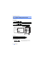 13
13
-
 14
14
-
 15
15
-
 16
16
-
 17
17
-
 18
18
-
 19
19
-
 20
20
-
 21
21
-
 22
22
-
 23
23
-
 24
24
-
 25
25
-
 26
26
-
 27
27
-
 28
28
-
 29
29
-
 30
30
-
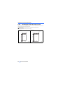 31
31
-
 32
32
-
 33
33
-
 34
34
-
 35
35
-
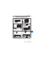 36
36
-
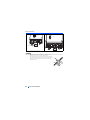 37
37
-
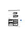 38
38
-
 39
39
-
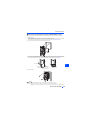 40
40
-
 41
41
-
 42
42
-
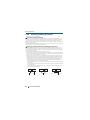 43
43
-
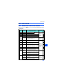 44
44
-
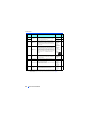 45
45
-
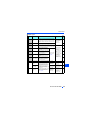 46
46
-
 47
47
-
 48
48
-
 49
49
-
 50
50
-
 51
51
-
 52
52
-
 53
53
-
 54
54
-
 55
55
-
 56
56
-
 57
57
-
 58
58
-
 59
59
-
 60
60
-
 61
61
-
 62
62
-
 63
63
-
 64
64
-
 65
65
-
 66
66
-
 67
67
-
 68
68
-
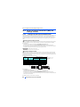 69
69
-
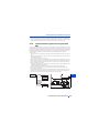 70
70
-
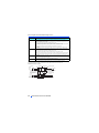 71
71
-
 72
72
-
 73
73
-
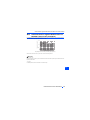 74
74
-
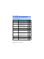 75
75
-
 76
76
-
 77
77
-
 78
78
-
 79
79
-
 80
80
-
 81
81
-
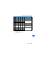 82
82
-
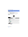 83
83
-
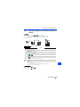 84
84
-
 85
85
-
 86
86
-
 87
87
-
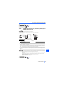 88
88
-
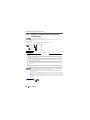 89
89
-
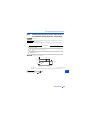 90
90
-
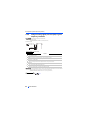 91
91
-
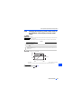 92
92
-
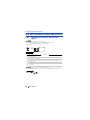 93
93
-
 94
94
-
 95
95
-
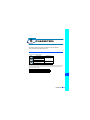 96
96
-
 97
97
-
 98
98
-
 99
99
-
 100
100
-
 101
101
-
 102
102
-
 103
103
-
 104
104
-
 105
105
-
 106
106
-
 107
107
-
 108
108
-
 109
109
-
 110
110
-
 111
111
-
 112
112
-
 113
113
-
 114
114
-
 115
115
-
 116
116
-
 117
117
-
 118
118
-
 119
119
-
 120
120
-
 121
121
-
 122
122
-
 123
123
-
 124
124
-
 125
125
-
 126
126
-
 127
127
-
 128
128
-
 129
129
-
 130
130
-
 131
131
-
 132
132
-
 133
133
-
 134
134
-
 135
135
-
 136
136
-
 137
137
-
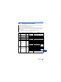 138
138
-
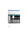 139
139
-
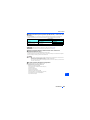 140
140
-
 141
141
-
 142
142
-
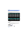 143
143
-
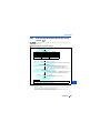 144
144
-
 145
145
-
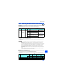 146
146
-
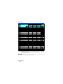 147
147
-
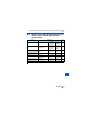 148
148
-
 149
149
-
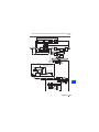 150
150
-
 151
151
-
 152
152
-
 153
153
-
 154
154
-
 155
155
-
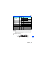 156
156
-
 157
157
-
 158
158
-
 159
159
-
 160
160
-
 161
161
-
 162
162
-
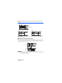 163
163
-
 164
164
-
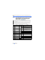 165
165
-
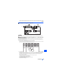 166
166
-
 167
167
-
 168
168
-
 169
169
-
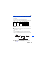 170
170
-
 171
171
-
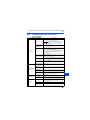 172
172
-
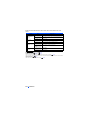 173
173
-
 174
174
-
 175
175
-
 176
176
-
 177
177
-
 178
178
-
 179
179
-
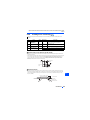 180
180
-
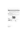 181
181
-
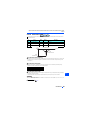 182
182
-
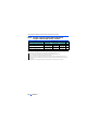 183
183
-
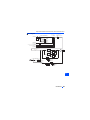 184
184
-
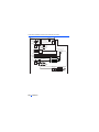 185
185
-
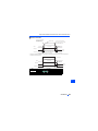 186
186
-
 187
187
-
 188
188
-
 189
189
-
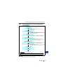 190
190
-
 191
191
-
 192
192
-
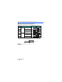 193
193
-
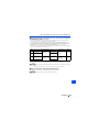 194
194
-
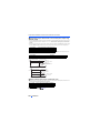 195
195
-
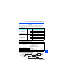 196
196
-
 197
197
-
 198
198
-
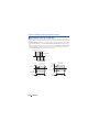 199
199
-
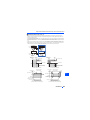 200
200
-
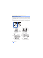 201
201
-
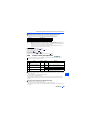 202
202
-
 203
203
-
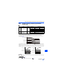 204
204
-
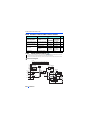 205
205
-
 206
206
-
 207
207
-
 208
208
-
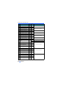 209
209
-
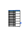 210
210
-
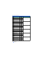 211
211
-
 212
212
-
 213
213
-
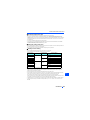 214
214
-
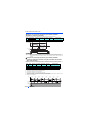 215
215
-
 216
216
-
 217
217
-
 218
218
-
 219
219
-
 220
220
-
 221
221
-
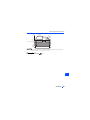 222
222
-
 223
223
-
 224
224
-
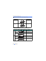 225
225
-
 226
226
-
 227
227
-
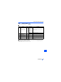 228
228
-
 229
229
-
 230
230
-
 231
231
-
 232
232
-
 233
233
-
 234
234
-
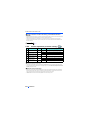 235
235
-
 236
236
-
 237
237
-
 238
238
-
 239
239
-
 240
240
-
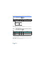 241
241
-
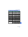 242
242
-
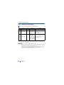 243
243
-
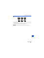 244
244
-
 245
245
-
 246
246
-
 247
247
-
 248
248
-
 249
249
-
 250
250
-
 251
251
-
 252
252
-
 253
253
-
 254
254
-
 255
255
-
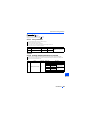 256
256
-
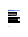 257
257
-
 258
258
-
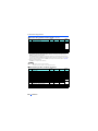 259
259
-
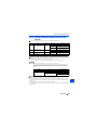 260
260
-
 261
261
-
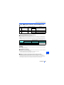 262
262
-
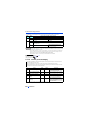 263
263
-
 264
264
-
 265
265
-
 266
266
-
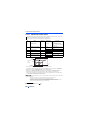 267
267
-
 268
268
-
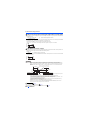 269
269
-
 270
270
-
 271
271
-
 272
272
-
 273
273
-
 274
274
-
 275
275
-
 276
276
-
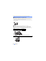 277
277
-
 278
278
-
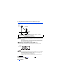 279
279
-
 280
280
-
 281
281
-
 282
282
-
 283
283
-
 284
284
-
 285
285
-
 286
286
-
 287
287
-
 288
288
-
 289
289
-
 290
290
-
 291
291
-
 292
292
-
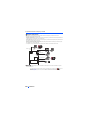 293
293
-
 294
294
-
 295
295
-
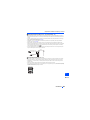 296
296
-
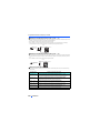 297
297
-
 298
298
-
 299
299
-
 300
300
-
 301
301
-
 302
302
-
 303
303
-
 304
304
-
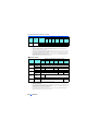 305
305
-
 306
306
-
 307
307
-
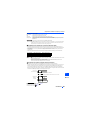 308
308
-
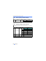 309
309
-
 310
310
-
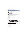 311
311
-
 312
312
-
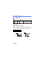 313
313
-
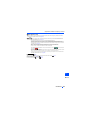 314
314
-
 315
315
-
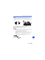 316
316
-
 317
317
-
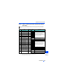 318
318
-
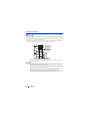 319
319
-
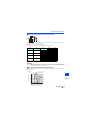 320
320
-
 321
321
-
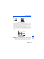 322
322
-
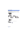 323
323
-
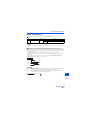 324
324
-
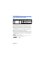 325
325
-
 326
326
-
 327
327
-
 328
328
-
 329
329
-
 330
330
-
 331
331
-
 332
332
-
 333
333
-
 334
334
-
 335
335
-
 336
336
-
 337
337
-
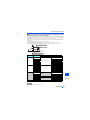 338
338
-
 339
339
-
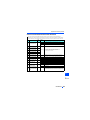 340
340
-
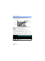 341
341
-
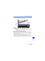 342
342
-
 343
343
-
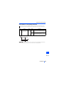 344
344
-
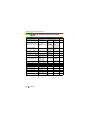 345
345
-
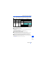 346
346
-
 347
347
-
 348
348
-
 349
349
-
 350
350
-
 351
351
-
 352
352
-
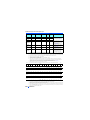 353
353
-
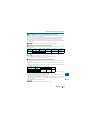 354
354
-
 355
355
-
 356
356
-
 357
357
-
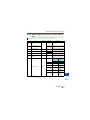 358
358
-
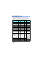 359
359
-
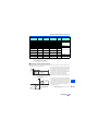 360
360
-
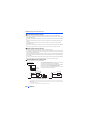 361
361
-
 362
362
-
 363
363
-
 364
364
-
 365
365
-
 366
366
-
 367
367
-
 368
368
-
 369
369
-
 370
370
-
 371
371
-
 372
372
-
 373
373
-
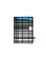 374
374
-
 375
375
-
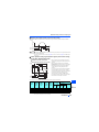 376
376
-
 377
377
-
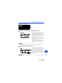 378
378
-
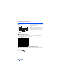 379
379
-
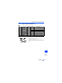 380
380
-
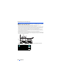 381
381
-
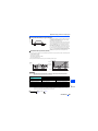 382
382
-
 383
383
-
 384
384
-
 385
385
-
 386
386
-
 387
387
-
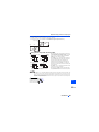 388
388
-
 389
389
-
 390
390
-
 391
391
-
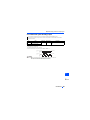 392
392
-
 393
393
-
 394
394
-
 395
395
-
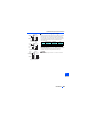 396
396
-
 397
397
-
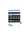 398
398
-
 399
399
-
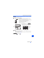 400
400
-
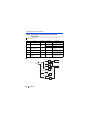 401
401
-
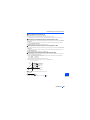 402
402
-
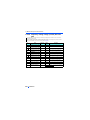 403
403
-
 404
404
-
 405
405
-
 406
406
-
 407
407
-
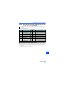 408
408
-
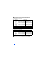 409
409
-
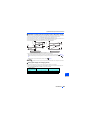 410
410
-
 411
411
-
 412
412
-
 413
413
-
 414
414
-
 415
415
-
 416
416
-
 417
417
-
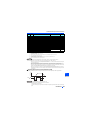 418
418
-
 419
419
-
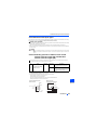 420
420
-
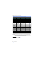 421
421
-
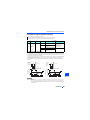 422
422
-
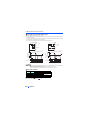 423
423
-
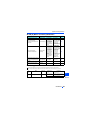 424
424
-
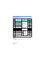 425
425
-
 426
426
-
 427
427
-
 428
428
-
 429
429
-
 430
430
-
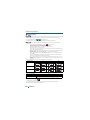 431
431
-
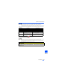 432
432
-
 433
433
-
 434
434
-
 435
435
-
 436
436
-
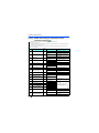 437
437
-
 438
438
-
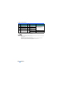 439
439
-
 440
440
-
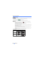 441
441
-
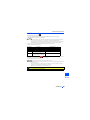 442
442
-
 443
443
-
 444
444
-
 445
445
-
 446
446
-
 447
447
-
 448
448
-
 449
449
-
 450
450
-
 451
451
-
 452
452
-
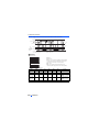 453
453
-
 454
454
-
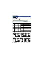 455
455
-
 456
456
-
 457
457
-
 458
458
-
 459
459
-
 460
460
-
 461
461
-
 462
462
-
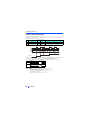 463
463
-
 464
464
-
 465
465
-
 466
466
-
 467
467
-
 468
468
-
 469
469
-
 470
470
-
 471
471
-
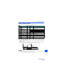 472
472
-
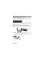 473
473
-
 474
474
-
 475
475
-
 476
476
-
 477
477
-
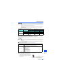 478
478
-
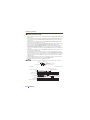 479
479
-
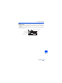 480
480
-
 481
481
-
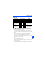 482
482
-
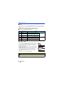 483
483
-
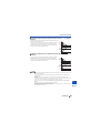 484
484
-
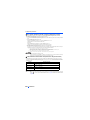 485
485
-
 486
486
-
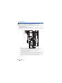 487
487
-
 488
488
-
 489
489
-
 490
490
-
 491
491
-
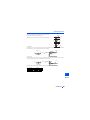 492
492
-
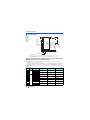 493
493
-
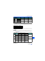 494
494
-
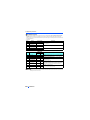 495
495
-
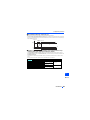 496
496
-
 497
497
-
 498
498
-
 499
499
-
 500
500
-
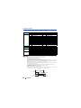 501
501
-
 502
502
-
 503
503
-
 504
504
-
 505
505
-
 506
506
-
 507
507
-
 508
508
-
 509
509
-
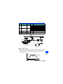 510
510
-
 511
511
-
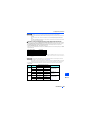 512
512
-
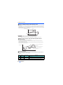 513
513
-
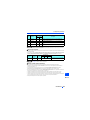 514
514
-
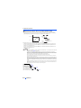 515
515
-
 516
516
-
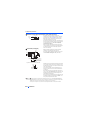 517
517
-
 518
518
-
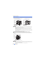 519
519
-
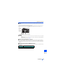 520
520
-
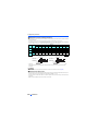 521
521
-
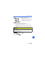 522
522
-
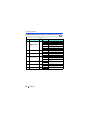 523
523
-
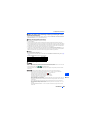 524
524
-
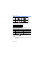 525
525
-
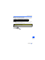 526
526
-
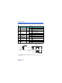 527
527
-
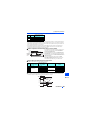 528
528
-
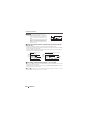 529
529
-
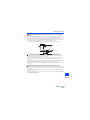 530
530
-
 531
531
-
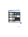 532
532
-
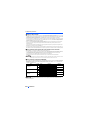 533
533
-
 534
534
-
 535
535
-
 536
536
-
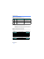 537
537
-
 538
538
-
 539
539
-
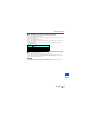 540
540
-
 541
541
-
 542
542
-
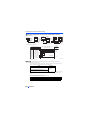 543
543
-
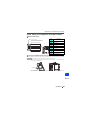 544
544
-
 545
545
-
 546
546
-
 547
547
-
 548
548
-
 549
549
-
 550
550
-
 551
551
-
 552
552
-
 553
553
-
 554
554
-
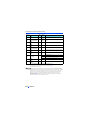 555
555
-
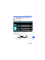 556
556
-
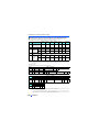 557
557
-
 558
558
-
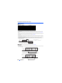 559
559
-
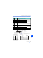 560
560
-
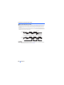 561
561
-
 562
562
-
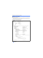 563
563
-
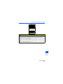 564
564
-
 565
565
-
 566
566
-
 567
567
-
 568
568
-
 569
569
-
 570
570
-
 571
571
-
 572
572
-
 573
573
-
 574
574
-
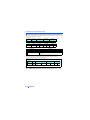 575
575
-
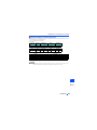 576
576
-
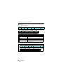 577
577
-
 578
578
-
 579
579
-
 580
580
-
 581
581
-
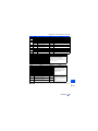 582
582
-
 583
583
-
 584
584
-
 585
585
-
 586
586
-
 587
587
-
 588
588
-
 589
589
-
 590
590
-
 591
591
-
 592
592
-
 593
593
-
 594
594
-
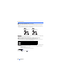 595
595
-
 596
596
-
 597
597
-
 598
598
-
 599
599
-
 600
600
-
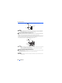 601
601
-
 602
602
-
 603
603
-
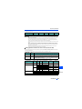 604
604
-
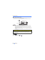 605
605
-
 606
606
-
 607
607
-
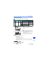 608
608
-
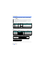 609
609
-
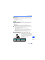 610
610
-
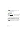 611
611
-
 612
612
-
 613
613
-
 614
614
-
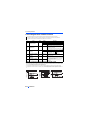 615
615
-
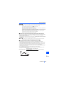 616
616
-
 617
617
-
 618
618
-
 619
619
-
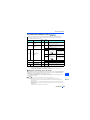 620
620
-
 621
621
-
 622
622
-
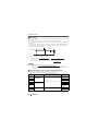 623
623
-
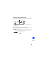 624
624
-
 625
625
-
 626
626
-
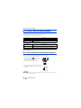 627
627
-
 628
628
-
 629
629
-
 630
630
-
 631
631
-
 632
632
-
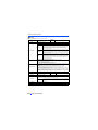 633
633
-
 634
634
-
 635
635
-
 636
636
-
 637
637
-
 638
638
-
 639
639
-
 640
640
-
 641
641
-
 642
642
-
 643
643
-
 644
644
-
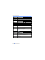 645
645
-
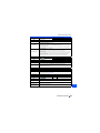 646
646
-
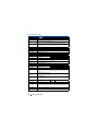 647
647
-
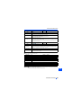 648
648
-
 649
649
-
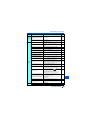 650
650
-
 651
651
-
 652
652
-
 653
653
-
 654
654
-
 655
655
-
 656
656
-
 657
657
-
 658
658
-
 659
659
-
 660
660
-
 661
661
-
 662
662
-
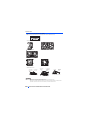 663
663
-
 664
664
-
 665
665
-
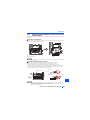 666
666
-
 667
667
-
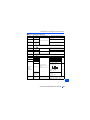 668
668
-
 669
669
-
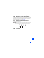 670
670
-
 671
671
-
 672
672
-
 673
673
-
 674
674
-
 675
675
-
 676
676
-
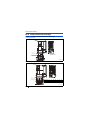 677
677
-
 678
678
-
 679
679
-
 680
680
-
 681
681
-
 682
682
-
 683
683
-
 684
684
-
 685
685
-
 686
686
-
 687
687
-
 688
688
-
 689
689
-
 690
690
-
 691
691
-
 692
692
-
 693
693
-
 694
694
-
 695
695
-
 696
696
-
 697
697
-
 698
698
-
 699
699
-
 700
700
-
 701
701
-
 702
702
-
 703
703
-
 704
704
-
 705
705
-
 706
706
-
 707
707
-
 708
708
-
 709
709
-
 710
710
-
 711
711
-
 712
712
-
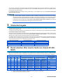 713
713
-
 714
714
-
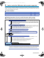 715
715
-
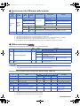 716
716
-
 717
717
-
 718
718
-
 719
719
-
 720
720
-
 721
721
-
 722
722
-
 723
723
-
 724
724
-
 725
725
-
 726
726
-
 727
727


Mitsubishi Electric FR-A860 (600V CLASS Owner's manual
- Category
- Power adapters & inverters
- Type
- Owner's manual
Ask a question and I''ll find the answer in the document
Finding information in a document is now easier with AI
Related papers
-
Mitsubishi Electric F800 User manual
-
Mitsubishi Electric FR-A862 User manual
-
-
-
-
-
-
-
-
Other documents
-
Hitachi INVERTER SJ700-2 User manual
-
Hitachi SJ700B-075H User manual
-
Toshiba Welding System VF-A7 User manual
-
Hitachi SJ100-005NFE User manual
-
-
Sharp SJ300 Series User manual
-
Hitachi SJ700D-550L User manual
-
-
-