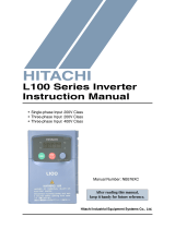
Hitachi SJ100-005NFE User manual

Type
User manual
HITACHI
SJ100 Series Inverter
Instruction Manual
Single-phase Input 200V Class
Three-phase Input 200V Class
Three-phase Input 400V Class
After reading this manual,
keep it handy for future reference.
Hitachi, Ltd.
Tokyo Japan
Manual Number: NB583XB
Glossary and
Bibliography
In This Appendix.... page
— Glossary ........................................................... 2
— Bibliography ..................................................... 8
A
Glossary
Appendix A
A–2
Glossary
Ambient Temperature
The air temperature in the chamber in which a powered electronic
unit resides. A unit’s heat sinks rely on a lower ambient temperature
in order to dissipate heat away from sensitive electronics.
Auto-tuning
The ability of a controller to execute a procedure that interacts with
a load to determine the proper coefficients to use in the control
algorithm. Auto-tuning is a common feature of process controllers
with PID loops. Hitachi inverters feature auto tuning to determine
motor parameters for optimal commutation. Auto-tuning is avail-
able as a special command from a digital operator panel. See also
digital operator panel.
Base Frequency
The power input frequency for which an AC induction motor is
designed to operate. Most motors will specify a 50 to 60 Hz value.
The Hitachi inverters have a programmable base frequency, so you
must ensure that parameter matches the attached motor. The term
base frequency helps differentiate it from the carrier frequency. See
also carrier frequency and frequency setting.
Braking Resistor
Some variable speed drives can cause the motor to develop deceler-
ating torque by switching motor wiring so the motor becomes a
generator, connected to an energy-absorbing resistor. See also four-
quadrant operation and dynamic braking.
Break-away Torque
The torque a motor must produce to overcome the static friction of a
load, in order to start the load moving.
Brushes
A sliding electrical connection between a fixed post inside the
motor housing and a ring on the motor shaft. Typically used in DC
motors or low-cost AC motors, brushes route current to windings on
the rotor. AC induction motors with a squirrel-cage design do not
have the need for brushes. See also commutation and squirrel cage.
Carrier Frequency
The frequency of the constant, periodic, switching waveform that
the inverter modulates to generate the AC output to the motor. See
also PWM.
CE
A regulatory agency for governing the performance of electronic
products in Europe. Drive installations designed to have CE
approval must have particular filter(s) installed in the application.
Choke
An inductor which is tuned to react at radio frequencies is called a
“choke,” since it attenuates (chokes) frequencies above a particular
threshold. Tuning is often accomplished by using a movable
magnetic core. In variable-frequency drive systems, a choke
positioned around high-current wiring can help attenuate harmful
harmonics and protect equipment. See also harmonics.
SJ100 Inverter
Appendix A
A3
DC Braking
The inverter DC braking feature stops the AC commutation to the
motor, and sends a DC current through the motor windings in order
to stop the motor. Also called DC injection braking, it has little
effect at high speed, and is used as the motor is nearing a stop.
Dead Band
In a control system, the range of input change for which there is no
perceptible change in the output. In PID loops, the error term may
have a dead band associated with it. Dead band may or may not be
desirable; it depends on the needs of the application.
Digital Operator Panel
For Hitachi inverters, digital operator panel (DOP) refers first to
the operator keypad on the front panel of the inverter. It also
includes hand-held remote keypads, which connect to the inverter
via a cable. Finally, the DOP Plus is a PC-based software simula-
tion of the keypad devices.
Diode
A semiconductor device which has a voltage-current characteristic
that allows current to flow only in one direction, with negligible
leakage current in the reverse direction. See also rectifier.
Duty Cycle
1. The percent of time a square wave of fixed frequency is on (high)
versus off (low). 2. The ratio of operating time of a motor, braking
resistor, etc. to its resting time. This parameter usually is specified
in association with the allowable thermal rise for the device.
Dynamic Braking
The inverter dynamic braking feature shunts the motor-generated
EMF energy into a special braking resistor. The added dissipation
(braking torque) is effective at higher speeds, having almost no
effect as the motor nears a stop.
Error
In process control, the error is the difference between the desired
value or setpoint (SP) and the actual value of a the process variable
(PV). See also process variable and PID Loop.
EMI
Electromagnetic Interference - In motor/drive systems, the switch-
ing of high currents and voltages creates the possibility of generat-
ing radiated electrical noise that may interfere with the operation of
nearby sensitive electrical instruments or devices. Certain aspects of
an installation, such as long motor lead wire lengths, tend to
increase the chance of EMI. Hitachi provides accessory filter
components you can install to decrease the level of EMI.
Four-quadrant
operation
Referring to a graph of torque versus direction, a four-quadrant
drive can turn the motor either forward or reverse, as well as decel-
erate in either direction (see also reverse torque). A load that has a
relatively high inertia and must move in both directions and change
directions rapidly requires four-quadrant capability from its drive.
Free-run Stop
A method of stopping a motor, caused when the inverter simply
turns off its motor output connections. This may allow the motor
and load to coast to a stop, or a mechanical brake may intervene and
shorten the deceleration time.
Glossary
Appendix A
A4
Frequency Setting
While frequency has a broad meaning in electronics, it typically
refers to motor speed for variable-frequency drives (inverters). This
is because the output frequency of the inverter is variable, and is
proportional to the attained motor speed. For example, a motor with
a base frequency of 60 Hz can be speed controlled with an inverter
output varying form 0 to 60 Hz. See also base frequency, carrier
frequency, and slip.
Harmonics
According to Fourier Series mathematics, a periodic (repeating)
function (waveform) can be expressed as a the summation of a
series of pure sine waves of related frequencies. The lowest
frequency is the fundamental, while all the other wave components
are called harmonics. The square waves used in inverters produce
high-frequency harmonics, even though the main goal is to produce
lower-frequency sine waves. These harmonics can be harmful to
electronics (including motor windings) and cause radiated energy
that interferes with nearby electronic devices. A choke is sometimes
used to suppress the transmission of harmonics in an electrical
system. See also choke.
Horsepower
A unit of physical measure to quantify the amount of work done per
unit of time. You can directly convert between horsepower and
Watts as measurements of power.
IGBT
Insulated Gate Bipolar Transistor
(IGBT) - a semiconductor
transistor capable of conducting very large currents when in satura-
tion and capable of withstanding very high voltages when it is off.
This high-power bipolar transistor is the type used in Hitachi invert-
ers.
Inertia
The natural resistance a stationary object to being moved by an
external force. See also momentum.
Intelligent Terminal
A configurable input or output logic function on the Hitachi invert-
ers. Each terminal may be assigned one of several functions.
Inverter
A device that electronically changes DC to AC current through a
alternating process of switching the input to the output, inverted and
non-inverted. A variable speed drive such as the Hitachi SJ100 is
also called an inverter, since it contains three inverter circuits to
generate 3-phase output to the motor.
Isolation Transformer
A transformer with 1:1 voltage ratio that provides electrical isola-
tion between its primary and secondary windings. These are
typically used on the power input side of the device to be protected.
An isolation transformer can protect equipment from a ground fault
or other malfunction of nearby equipment, as well as attenuate
harmful harmonics and transients on the input power.
Jogging Operation
Usually done manually, a jog command from an operators panel
requests the motor/drive system to run indefinitely in a particular
direction, until the machine operator ends the jog operation.
SJ100 Inverter
Appendix A
A5
Momentum
The physical property of a body in motion that causes it to continue
to move in a straight line. In the case of motors, the armature and
shaft are rotating and possesses angular momentum.
Multi-speed Operation
The ability of a motor drive to store preset discrete speed levels for
the motor, and control motor speed according to the currently
selected speed preset. The Hitachi inverters have 16 preset speeds.
Motor Load
In motor terminology, motor load consists of the inertia of the
physical mass that is moved by the motor and the related friction
from guiding mechanisms. See also inertia.
NEC
The National Electric Code is a regulatory document that governs
electrical power and device wiring and installation in the United
States.
NEMA
The National Electric Manufacturers Association. NEMA Codes
are a published series of device ratings standards. Industry uses
these to evaluate or compare the performance of devices made by
various manufacturers to a known standard.
Power Factor
A ratio that expresses a phase difference (timing offset) between
current and voltage supplied by a power source to a load. A perfect
power factor = 1.0 (no phase offset). Power factors less than one
cause some energy loss in power transmission wiring (source to
load).
PID Loop
Proportional - Integral-Derivative - a mathematical model used for
process control. A process controller maintains a process variable
(PV) at a setpoint (SP) by using its PID algorithm to compensate for
dynamic conditions and vary its output to drive the PV toward the
desired value. For variable-frequency drives, the process variable is
the motor speed. See also error.
Process Variable
A physical property of a process which is of interest because it
affects the quality of the primary task accomplished by the process.
For an industrial oven, temperature is the process variable. See also
PID Loop and error.
PWM
Pulse-width modulation: A type of AC adjustable frequency drive
that accomplishes frequency and voltage control at the output
section(inverter) of the drive. The drive output voltage waveform is
at a constant amplitude, and by "chopping" the waveform (pulse-
width-modulating), the average voltage is controlled. The chopping
frequency is sometimes called the carrier frequency.
Reactance
The impedance of inductors and capacitors has two components.
The resistive part is constant, while the reactive part changes with
applied frequency. These devices have a complex impedance
(complex number), where the resistance is the real part and the
reactance is the imaginary part.
Glossary
Appendix A
A6
Rectifier
An electronic device made of one or more diodes which converts
AC power into DC power. Rectifiers are usually used in combina-
tion with capacitors to filter (smooth) the rectified waveform to
closely approximate a pure DC voltage source.
Regenerative Braking
A particular method of generating reverse torque to a motor, an
inverter will switch internally to allow the motor to become a gener-
ator and will store the energy internally and/or deliver the braking
energy back to the power input mains.
Regulation
The quality of control applied to maintain a parameter of interest at
a desired value. Usually expressed as a percent (+/-) from the
nominal, motor regulation usually refers to its shaft speed.
Reverse Torque
The force of available from some types of inverters to change the
direction of rotation of a motor shaft. As such, reverse torque is a
decelerating force on the motor and its external load.
Rotor
The windings of a motor that rotate, being physically coupled to the
motor shaft. See also stator.
Saturation Voltage
For a transistor semiconductor device, it is in saturation when an
increase in input (gate) current no longer results in an increase in
the output (source/drain) current. The saturation voltage is the
voltage from the power source to the transistor output (Vsource to
Vdrain). The ideal saturation voltage is zero.
Sensorless Vector
Control
A technique used in variable-frequency drives to rotate the force
vector in the motor without the use of a shaft position sensor
(angular). Benefits include an increase in torque at the lowest speed
and the cost savings from the lack of a shaft position sensor.
Setpoint (SP)
The setpoint is the desired value of a process variable of interest.
See also Process Variable (PV) and PID Loop.
Single-phase
An AC power source consisting of Hot and Neutral wires. An Earth
Ground connection usually accompanies them. In theory, the
voltage potential on Neutral stays at or near Earth Ground, while
Hot varies sinusoidally above and below Neutral. This power source
is named Single Phase to differentiate it from three-phase power
sources. Some Hitachi inverters can accept single phase input
power, but they all output three-phase power to the motor. See also
three-phase.
Slip
The difference between the theoretical speed of a motor at no load
(determined by its inverter output waveforms) and the actual speed.
Some slip is essential in order to develop torque to the load, but too
much will cause excessive heat in the motor windings and/or cause
the motor to stall.
Squirrel Cage
A nick-name for the appearance of the rotor frame assembly for
an AC induction motor.
SJ100 Inverter
Appendix A
A7
Stator
The windings in a motor that are stationary and coupled to the
power input of the motor. See also rotor.
Tachometer
1. A signal generator usually attached to the motor shaft for the
purpose of providing feedback to the speed controlling device of
the motor. 2. A speed-monitoring test meter which may optically
sense shaft rotation speed and display it on a readout.
Thermal Switch
An electromechanical safety device that opens to stop current flow
when the temperature at the device reaches a specific temperature
threshold. In variable-speed drive systems, thermal switches are
typically installed at or near the motor, in order to protect the
windings from heat damage.
Three-phase
An AC power source with three Hot connections that have phase
offsets of 120 degrees is a 3-phase power source. Usually, Neutral
and Earth Ground wires accompany the three Hot connections.
Loads may be configured in a delta or Y configuration. A Y-
connected load such as an AC induction motor will be a balanced
load; the currents in all the Hot connections are the same. There-
fore, the Neutral connection is theoretically zero. This is why
inverters, which generate 3-phase power for motors, do not gener-
ally have a Neutral connection to the motor. However, the Earth
Ground connection is important for safety reasons, and is provided.
Torque
The rotational force exerted by a motor shaft. The units of measure-
ment consist of the distance (radius from shaft center axis) and
force (weight) applied at that distance. Units are usually given as
pound-feet, ounce-inches, or Newton-meters.
Transistor
A solid state, three-terminal device that provides amplification of
signals and can be used for switching and control. While transistors
have a linear operating range, inverters use them as high-powered
switches. Recent developments in power semiconductors has
produced transistors capable of handling hundreds of volts and tens
of Amperes or more, all with high reliability. The saturation voltage
has been decreasing, resulting in less heat dissipation. Hitachi
inverters use state-of-the-art semiconductors to provide high perfor-
mance and reliability, all in a compact package. See also IGBT and
saturation voltage.
Trip
An event which causes the inverter to stop operation is called a
trip event (as in tripping a circuit breaker). The inverter keeps a
history log of trip events. They also require an action to clear.
Bibliography
Appendix A
A8
Bibliography
Title Author and Publisher
Variable Speed Drive Fundamentals, 2nd Ed. Phipps, Clarence A.
The Fairmont Press, Inc. / Prentice-Hall, Inc. 1997
ISBN 0-13-636390-3
Electronic Variable Speed Drives Brumbach, Michael E.
Delmar Publishers 1997
ISBN 0-8273-6937-9
Hitachi Inverter Technical Guide Book Published by Hitachi, Ltd. Japan 1995
Publication SIG-E002
Drive Parameter
Settings Tables
In This Appendix.... page
— Introduction ...................................................... 2
— Parameter Settings for Keypad Entry............... 2
— Parameter Settings for DOP/DRW/DOP Plus .. 9
B
Introduction
Appendix B
B–2
Introduction
This appendix lists the user-programmable parameters for the SJ100 series inverters and
the default values for European and U.S. product types. The right-most column of the
tables is blank, so you can record values you have changed from the default. This
involves just a few parameters for most applications. The two sections in this appendix
present the parameters in a format oriented toward two different programming devices:
the keypad on the inverter, and
the digital operator panel software (DOP Plus) for the PC
Please refer to the section corresponding to your preferred programming tool.
Parameter Settings for Keypad Entry
SJ100 series inverters provide many functions and parameters which can be configured
by the user. We recommend that you record all parameters which have been edited, in
order to help in troubleshooting or recovery from a loss of parameter data.
Main Profile Parameters
Inverter model
MFG. No.
SJ100
}
This information is printed
on the specification label
located on the right side of
the inverter.
“F” Group Parameters Default Setting
User Setting
Func. Code Name -FE (Europe) -FU (USA)
F01 Output frequency setting 0.0 0.0
F02 Acceleration 1 10.0 10.0
F202 Acceleration 1, 2nd motor 10.0 10.0
F03 Deceleration 1 10.0 10.0
F203 Deceleration 1, 2nd motor 10.0 10.0
F04 Running direction setting 0.0 0.0
SJ100 Inverter
Appendix B
B3
Standard Functions
A Group Parameters Default Setting
User Setting
Func. Code Name -FE (Europe) -FU (USA)
A01 Frequency source setting 01 01
A02 Run command source setting 01 01
A03 Base frequency setting 50.0 60.0
A203 Base frequency setting, 2nd motor 50.0 60.0
A04 Maximum frequency setting 50.0 60.0
A204 Maximum frequency setting, 2nd
motor
50.0 60.0
A11 External frequency output zero
reference
00
A12 External frequency output span refer-
ence
00
A13 External frequency input bias start 0 0
A14 External frequency input bias end 100 100
A15 External frequency offset enable 01 01
A16 External frequency filter time const. 8 8
A20 Multi-speed 0 setting 0 0
A220 Multi-speed 0 setting, 2nd motor 0 0
A21 Multi-speed 1 setting 0 0
A22 Multi-speed 2 setting 0 0
A23 Multi-speed 3 setting 0 0
A24 Multi-speed 4 setting 0 0
A25 Multi-speed 5 setting 0 0
A26 Multi-speed 6 setting 0 0
A27 Multi-speed 7 setting 0 0
A28 Multi-speed 8 setting 0 0
A29 Multi-speed 9 setting 0 0
A30 Multi-speed 10 setting 0 0
A31 Multi-speed 11 setting 0 0
A32 Multi-speed 12 setting 0 0
A33 Multi-speed 13 setting 0 0
A34 Multi-speed 14 setting 0 0
A35 Multi-speed 15 setting 0 0
Parameter Settings for Keypad Entry
Appendix B
B4
A38 Jog frequency setting 1.0 1.0
A39 Jog stop mode 00 00
A41 Torque boost method selection 0 0
A241 Torque boost method selection, 2nd
motor
00
A42 Manual torque boost value 11 11
A242 Manual torque boost value, 2nd
motor
11 11
A43 Manual torque boost frequency
adjustment
10.0 10.0
A243 Manual torque boost frequency
adjustment, 2nd motor
10.0 10.0
A44 V/F characteristic curve selection 02 02
A244 V/F characteristic curve selection,
2nd motor
02 02
A45 V/F gain setting 100 100
A51 DC braking enable 00 00
A52 DC braking frequency setting 0.5 0.5
A53 DC braking wait time 0.0 0.0
A54 DC braking force setting 0 0
A55 DC braking time setting 0.0 0.0
A61 Frequency upper limit setting 0.0 0.0
A62 Frequency lower limit setting 0.0 0.0
A63, A65,
A67
Jump (center) frequency setting 0.0 0.0
A64, A66,
A68
Jump (hysteresis) frequency width
setting
0.5 0.5
A71 PID Function Enable 00 00
A72 PID proportional gain 1.0 1.0
A73 PID integral time constant 1.0 1.0
A74 PID derivative gain 0.0 0.0
A75 PV scale conversion 1.00 1.00
A76 PV source setting 00 00
A81 AVR function select 02 02
A82 AVR voltage select 230/400 230/460
A Group Parameters Default Setting
User Setting
Func. Code Name -FE (Europe) -FU (USA)
SJ100 Inverter
Appendix B
B5
A92 Second acceleration time setting 15.0 15.0
A292 Second acceleration time setting
(2nd motor)
15.0 15.0
A93 Second deceleration time setting 15.0 15.0
A293 Second deceleration time setting
(2nd motor)
15.0 15.0
A94 Select method to use second accel/
decel
00 00
A294 Select method to use second accel/
decel, 2nd motor
00 00
A95 Acc1 to Acc2 frequency transition
point
0.0 0.0
A295 Acc1 to Acc2 frequency transition
point, 2nd motor
0.0 0.0
A96 Dec1 to Dec2 frequency transition
point
0.0 0.0
A296 Dec1 to Dec2 frequency transition
point, 2nd motor
0.0 0.0
A97 Acceleration curve selection 00 00
A98 Deceleration curve setting 00 00
A Group Parameters Default Setting
User Setting
Func. Code Name -FE (Europe) -FU (USA)
Parameter Settings for Keypad Entry
Appendix B
B6
Fine Tuning Functions
B Group Parameters Default Setting
User Setting
Func. Code Name -FE (Europe) -FU (USA)
B01 Selection of restart mode 00 00
B02 Allowable under-voltage power
failure time
1.0 1.0
B03 Delay before motor restart time 1.0 1.0
B12 Level of electronic thermal setting Rated current
for each
inverter
Rated current
for each
inverter
B212 Level of electronic thermal setting,
2nd motor
Rated current
for each
inverter
Rated current
for each
inverter
B13 Electronic thermal characteristic 01 01
B213 Electronic thermal characteristic,
2nd motor
01 01
B21 Overload restriction operation mode 01 01
B22 Overload restriction setting Rated current
x 1.25
Rated current
x 1.25
B23 Deceleration rate at overload restric-
tion
1.0 1.0
B31 Software lock mode selection 01 01
B32 Reactive current setting Rated current
x 0.58
Rated current
x 0.58
B81 Analog frequency meter adjustment 80 80
B82 Start frequency adjustment 0.5 0.5
B83 Carrier frequency setting 5.0 5.0
B84 Initialization mode (parameters or
trip history)
00 00
B85 Country code for initialization 01 02
B86 Frequency scalar conversion factor 1.0 1.0
B87 STOP key enable 00 00
B88 Resume on FRS cancellation mode 00 00
B89 Data select for digital op. OPE-J 01 01
B90 Dynamic braking usage ratio 0.0 0.0
B91 Stop mode selection 00 00
B92 Cooling fan control 00 00
SJ100 Inverter
Appendix B
B7
Intelligent Terminal Functions
C Group Parameters Default Setting
User Setting
Func. Code Name -FE (Europe) -FU (USA)
C01 Terminal 1 function 00 00
C02 Terminal 2 function 01 01
C03 Terminal 3 function 02 16
C04 Terminal 4 function 03 13
C05 Terminal 5 function 18 09
C06 Terminal 6 function 09 18
C11 Terminal 1 active state 00 00
C12 Terminal 2 active state 00 00
C13 Terminal 3 active state 00 00
C14 Terminal 4 active state 00 01
C15 Terminal 5 active state 00 00
C16 Terminal 6 active state 00 00
C21 Terminal 11 function (logical) 01 01
C22 Terminal 12 function (logical) 00 00
C23 Terminal FM function (analog) 00 00
C24 Alarm relay terminal function
(logical)
05 05
C31 Terminal 11 active state 00 00
C32 Terminal 12 active state 00 00
C33 Alarm relay active state 01 01
C41 Overload level setting Inverter rated
current
Inverter rated
current
C42 Frequency arrival setting for accel. 0.0 0.0
C43 Arrival frequency setting for decel. 0.0 0.0
C44 PID deviation level setting 3.0 3.0
C81 Analog meter adj., voltage input Factory-set Factory-set
C82 Analog meter adj., current input Factory-set Factory-set
C91 Debug mode selection 00 00 Do not edit
C92 Core monitor address 0000 0000 Do not edit
C93 Core monitor date ——Do not edit
C94 Core set address d001 d001 Do not edit
C95 Core set date 00 00 Do not edit
Parameter Settings for Keypad Entry
Appendix B
B8
Sensorless Vector Functions
H Group Parameters Default Setting
User Setting
Func. Code Name -FE (Europe) -FU (USA)
H21 Auto-tuning Setting 00 00
H02 Motor data selection 00 00
H202 Motor data selection, 2nd motor 00 00
H03 Motor capacity Specified by
the inverter
capacity
Specified by
the inverter
capacity
H203 Motor capacity, 2nd setting Specified by
the inverter
capacity
Specified by
the inverter
capacity
H04 Motor poles setting 4 4
H204 Motor poles setting, 2nd motor 4 4
H05 Motor constant Kp 20 20
H205 Motor constant Kp, 2nd motor 20 20
H06 Motor stabilization constant 100 100
H206 Motor stabilization constant, 2nd
motor
100 100
H20 Motor constant R1 Factory set Factory set
H220 Motor constant R1, 2nd motor Factory set Factory set
H21 Motor constant R2 Factory set Factory set
H221 Motor constant R2, 2nd motor Factory set Factory set
H22 Motor constant L Factory set Factory set
H222 Motor constant L, 2nd motor Factory set Factory set
H23 Motor constant Io Factory set Factory set
H223 Motor constant Io, 2nd motor Factory set Factory set
H24 Motor Constant J Factory set Factory set
H224 Motor constant J, 2nd motor Factory set Factory set
SJ100 Inverter
Appendix B
B9
Parameter Settings for DOP/DRW/DOP Plus
SJ100 series inverters provide many functions and parameters which can be configured
by the user. We recommend that you record all parameters which have been edited, in
order to help in troubleshooting or recovery from a loss of parameter data.
Monitor Mode Parameters
Inverter model
MFG. No.
SJ100
}
This information is printed
on the specification label
located on the right side of
the inverter.
Monitor Mode Setup Displayed Default Setting
User Setting
Func.
Code
Name -FE (Europe) -FU (USA)
Mon. Frequency setting TM 026.4 0.0Hz TM 031.6 0.0Hz
Acceleration time ACC 0010.0s ACC 0010.0s
Acceleration time, 2nd
motor
2ACC 0010.0s 2ACC 0010.0s
Deceleration time DEC 0010.0s DEC 0010.0s
Deceleration time, 2nd
motor
2DEC 0010.0s 2DEC 0010.0s
Frequency setting F-SET-SELECT TRM F-SET-SELECT TRM
Frequency source select F/R-SELECT TRM F/R-SELECT TRM
Scaled frequency value /Hz01.0 0.00 /Hz01.0 0.00
Output current display Im 0.0A 0.0% Im 0.0A 0.0%
Manual torque boost V-Boost code 11 V-Boost code 11
Manual torque boost,
2nd motor
2V-Boost code 11 2V-Boost code 11
Torque boost frequency
setting
V-Boost F 10.0% V-Boost F 10.0%
Torque boost frequency
setting, 2nd motor
2V-Boost F 10.0% 2V-Boost F 10.0%
Torque boost mode V-Boost Mode 0 V-Boost Mode 0
Torque boost mode, 2nd
motor
2V-Boost Mode 0 2V-Boost Mode 0
Output voltage gain adj. V-Gain 100% V-Gain 100%
Jog frequency Jogging 1.00Hz Jogging 1.00Hz
Jog mode select Jog Mode 0 Jog Mode 0
Parameter Settings for DOP/DRW/DOP Plus
Appendix B
B10
Function Mode Setup
Mon. Analog voltage input
adjustment
ADJ-O 097 ADJ-O 097
Analog current input
adjustment
ADJ-OI 079 ADJ-OI 079
Analog adjustment ADJ 080 ADJ 080
Panel display selection PANEL d01 PANEL d01
Terminal monitor TERM LLL LLLLLL TERM LLL LLLLLL
Accumulation of Run
Mode time since mfg.
RUN 000003H RUN 000003H
Alarm display ERR1 Under.V ERR1 Under.V
ERR1 10.0Hz ERR1 10.0Hz
ERR1 0.2A ERR1 0.2A
ERR1 189.8Vdc ERR1 189.8Vdc
ERR1 RUN 000003H ERR1 RUN 000003H
Total alarm count ERROR COUNT 002 ERROR COUNT 002
Trip history, previous
alarm (example)
ERR2 Under.V ERR2 Under.V
ERR2 10.0Hz ERR2 10.0Hz
ERR2 0.2A ERR2 0.2A
ERR2 189.8Vdc ERR2 189.8Vdc
ERR2 RUN 000003H ERR2 RUN 000003H
Trip history, 2nd
previous alarm
ERR3 # ERR3 #
Monitor Mode Setup Displayed Default Setting
User Setting
Func.
Code
Name -FE (Europe) -FU (USA)
Function Mode Setup Displayed Default Setting
User Setting
Func.
Code
Name -FE (Europe) -FU (USA)
F-00
Base frequency setting F-BASE 050Hz F-BASE 060Hz
F-01
Maximum frequency
setting
F-MAX 050Hz F-MAX 060Hz
F-02
Start frequency adjust-
ment
Fmin 0.5Hz Fmin 0.5Hz
F-03
Motor input voltage AVR AC 230V AVR AC 230V
AVR function for decel-
eration
AVR MODE DOFF AVR MODE DOFF
SJ100 Inverter
Appendix B
B11
F-04
Control method setting CONTROL SLV CONTROL SLV
F-05
Auto-tuning setting AUX AUTO NOR AUX AUTO NOR
Motor date selection AUX DATA NOR AUX DATA NOR
Motor date selection,
2nd motor
2AUXDATA NOR 2AUXDATA NOR
Motor capacity setting AUX K 0.4 kW AUX K 0.4 kW
Motor capacity setting,
2nd motor
2AUXK 0.4 kW 2AUXK 0.4 kW
Motor pole count setting AUX P 4p AUX P 4p
Motor pole count
setting, 2nd motor
2AUXP 4p 2AUXP 4p
Motor constant R1
setting
AUX R1 06.333ô AUX R1 05.700ô
Motor constant R1
setting, 2nd motor
2AUXR1 06.333ô 2AUXR1 05.700ô
Motor constant R2
setting
AUX R2 03.200ô AUX R2 02.773ô
Motor constant R2
setting, 2nd motor
2AUXR2 03.200ô 2AUXR2 02.773ô
Motor constant L setting AUX L 027.50mH AUX L 045.70mH
Motor constant L
setting, 2nd motor
2AUXL 027.50mH 2AUXL 045.70mH
Motor constant IO
setting
AUX I0 001.48A AUX I0 001.50A
Motor constant IO
setting, 2nd motor
2AUXI0 001.48A 2AUXI0 001.50A
Motor constant J setting AUX J 0020.0 AUX J 0020.0
Motor constant J setting,
2nd motor
2AUXJ 0020.0 2AUXJ 0020.0
Motor constant Kp
setting
AUX KP 20 AUX KP 20
Motor constant Kp
setting, 2nd motor
2AUXKP 20 2AUXKP 20
Motor stabilization
constant setting
AUX KCD 100 AUX KCD 100
Motor stabilization
constant, 2nd motor
2AUXKCD 100 2AUXKCD 100
Function Mode Setup Displayed Default Setting
User Setting
Func.
Code
Name -FE (Europe) -FU (USA)
  • Page 1 1
  • Page 2 2
  • Page 3 3
  • Page 4 4
  • Page 5 5
  • Page 6 6
  • Page 7 7
  • Page 8 8
  • Page 9 9
  • Page 10 10
  • Page 11 11
  • Page 12 12
  • Page 13 13
  • Page 14 14
  • Page 15 15
  • Page 16 16
  • Page 17 17
  • Page 18 18
  • Page 19 19
  • Page 20 20
  • Page 21 21
  • Page 22 22
  • Page 23 23
  • Page 24 24
  • Page 25 25
  • Page 26 26
  • Page 27 27
  • Page 28 28
  • Page 29 29
  • Page 30 30
  • Page 31 31
  • Page 32 32
  • Page 33 33
  • Page 34 34
  • Page 35 35
  • Page 36 36
  • Page 37 37
  • Page 38 38
  • Page 39 39
  • Page 40 40
  • Page 41 41
  • Page 42 42
  • Page 43 43
  • Page 44 44
  • Page 45 45
  • Page 46 46
  • Page 47 47
  • Page 48 48
  • Page 49 49
  • Page 50 50
  • Page 51 51
  • Page 52 52
  • Page 53 53
  • Page 54 54
  • Page 55 55
  • Page 56 56
  • Page 57 57
  • Page 58 58
  • Page 59 59
  • Page 60 60
  • Page 61 61
  • Page 62 62
  • Page 63 63
  • Page 64 64
  • Page 65 65
  • Page 66 66
  • Page 67 67
  • Page 68 68
  • Page 69 69
  • Page 70 70
  • Page 71 71
  • Page 72 72
  • Page 73 73
  • Page 74 74
  • Page 75 75
  • Page 76 76
  • Page 77 77
  • Page 78 78
  • Page 79 79
  • Page 80 80
  • Page 81 81
  • Page 82 82
  • Page 83 83
  • Page 84 84
  • Page 85 85
  • Page 86 86
  • Page 87 87
  • Page 88 88
  • Page 89 89
  • Page 90 90
  • Page 91 91
  • Page 92 92
  • Page 93 93
  • Page 94 94
  • Page 95 95
  • Page 96 96
  • Page 97 97
  • Page 98 98
  • Page 99 99
  • Page 100 100
  • Page 101 101
  • Page 102 102
  • Page 103 103
  • Page 104 104
  • Page 105 105
  • Page 106 106
  • Page 107 107
  • Page 108 108
  • Page 109 109
  • Page 110 110
  • Page 111 111
  • Page 112 112
  • Page 113 113
  • Page 114 114
  • Page 115 115
  • Page 116 116
  • Page 117 117
  • Page 118 118
  • Page 119 119
  • Page 120 120
  • Page 121 121
  • Page 122 122
  • Page 123 123
  • Page 124 124
  • Page 125 125
  • Page 126 126
  • Page 127 127
  • Page 128 128
  • Page 129 129
  • Page 130 130
  • Page 131 131
  • Page 132 132
  • Page 133 133
  • Page 134 134
  • Page 135 135
  • Page 136 136
  • Page 137 137
  • Page 138 138
  • Page 139 139
  • Page 140 140
  • Page 141 141
  • Page 142 142
  • Page 143 143
  • Page 144 144
  • Page 145 145
  • Page 146 146
  • Page 147 147
  • Page 148 148
  • Page 149 149
  • Page 150 150
  • Page 151 151
  • Page 152 152
  • Page 153 153
  • Page 154 154
  • Page 155 155
  • Page 156 156
  • Page 157 157
  • Page 158 158
  • Page 159 159
  • Page 160 160

Hitachi SJ100-005NFE User manual

Type
User manual

Ask a question and I''ll find the answer in the document

Finding information in a document is now easier with AI