Page is loading ...

DOC026.53.80437
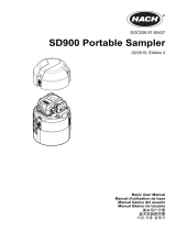
SD900 Portable Sampler
02/2015, Edition 2
User Manual


Table of Contents
Specifications.............................................................................................................. 3
General information.................................................................................................. 4
Safety information........................................................................................................ 5
Use of hazard information.................................................................................... 5
Precautionary labels............................................................................................. 5
Certification........................................................................................................... 5
Product overview......................................................................................................... 6
Product components.................................................................................................... 7
Installation..................................................................................................................... 8
Confined space precautions........................................................................................ 8
Mechanical installation................................................................................................. 8
Site installation guidelines.................................................................................... 8
Install the sampler in a manhole........................................................................... 9
Install the distributor or full-bottle shutoff (optional).............................................. 9
Prepare the sampler............................................................................................. 9
Clean the sample bottles............................................................................... 9
Install a single bottle...................................................................................... 9
Install the first bottle for multiple sample collections..................................... 9
Install multiple bottles.................................................................................. 10
Plumb the sampler...................................................................................... 11
Electrical installation.................................................................................................. 12
Controller connections........................................................................................ 12
Connect a flow meter.......................................................................................... 13
Connect a PC or communications network........................................................ 13
Connect an SDI-12 device.................................................................................. 14
Connect the sampler to power............................................................................ 14
Calculate the pump cycle time............................................................................ 15
Close the cover.......................................................................................................... 16
Set the power to on................................................................................................. 16
User interface and navigation............................................................................ 16
Operation..................................................................................................................... 17
Main menu overview.................................................................................................. 17
Configure the system settings................................................................................... 17
Configure the SDI-12 device.............................................................................. 18
Set up a sampling program........................................................................................ 19
Time based collection......................................................................................... 21
Use variable volume.................................................................................... 21
Do not use variable volume......................................................................... 21
Flow based collection......................................................................................... 21
Use counts for the flow source.................................................................... 21
Use 4–20 mA input for the flow source....................................................... 22
Review or modify program settings.................................................................... 22
Save or load programs....................................................................................... 22
Restore the default settings................................................................................ 22
Constant Time Variable Volume (CTVV) sampling............................................ 23
1

Start or stop a program.............................................................................................. 24
View the program status............................................................................................ 24
Manual operation....................................................................................................... 24
Collect a grab sample......................................................................................... 24
Move the distributor arm..................................................................................... 25
Start or stop the pump........................................................................................ 25
View data................................................................................................................... 25
View the sample history...................................................................................... 25
View the event log.............................................................................................. 26
Event log information................................................................................... 26
Erase the event log..................................................................................... 26
View data from SDI-12 devices.......................................................................... 26
Volume calibration..................................................................................................... 27
Calibrate the liquid sensor.................................................................................. 27
Restore the default calibration............................................................................ 27
Calibrate the sample volume with the liquid sensor........................................... 27
Calibrate the sample volume manually............................................................... 28
Verify the sample volume................................................................................... 28
Full bottle shutoff....................................................................................................... 28
Activate the full bottle shutoff.............................................................................. 29
Enable the full bottle shutoff............................................................................... 29
Full bottle shutoff in non-continuous mode......................................................... 29
Full bottle shut off in continuous mode............................................................... 29
Full bottle shutoff and timed bottle mode.................................................... 30
Full bottle shutoff exception conditions............................................................... 30
Advanced sampling................................................................................................ 30
Send output signal at program completion................................................................ 30
Send output signal with sample cycle (special output).............................................. 31
Operate from an external signal (setpoint sample).................................................... 31
Use an SDI-12 device for setpoint sampling ..................................................... 31
Set multiple start and stop times................................................................................ 32
Collect first flush stormwater samples....................................................................... 33
Set variable intervals................................................................................................. 33
Timed bottle sets....................................................................................................... 34
Maintenance............................................................................................................... 34
Clean the instrument.................................................................................................. 35
Replace the desiccant............................................................................................... 35
Pump maintenance.................................................................................................... 36
Replace the pump tubing.................................................................................... 36
Clean the rotor.................................................................................................... 38
Replace the distributor arm tube................................................................................ 39
Fuse replacement...................................................................................................... 39
Troubleshooting....................................................................................................... 39
General troubleshooting............................................................................................ 39
Error messages......................................................................................................... 40
Diagnostic tests......................................................................................................... 42
Replacement parts and accessories............................................................... 42
Table of Contents
2

Specifications
Specifications are subject to change without notice.
SD900 Portable Sampler
Specification Standard base Compact base Composite base
Dimensions Diameter: 50.5 cm (19.9 in.)
Height: 69.4 cm (27.3 in.)
Diameter: 44.1 cm (17.4 in.)
Height: 61 cm (24 in.)
Diameter: 50.28 cm
(19.8 in.)
Height: 79.75 cm
(31.4 in.)
Weight 15 kg (35.6 lb) with 1-L
polyethylene bottles (24x)
14.8 kg (32.6 lb) with 10-L (2.5 gal)
polyethylene container (1x)
12.2 kg (27 lb) with 575-mL
(19.44 oz) polyethylene
bottles (24x)
12.9 kg (28.3 lb) with 10-L
(2.5 gal) polyethylene
container (1x)
15 kg (36 lb) with 950-
mL (32.12 oz) glass
bottles (12x)
Enclosure Impact-resistant ABS, 3-section construction; double-walled base with 2.54 cm (1 in.)
insulation—direct bottle contact with ice.
Sample
temperature
0–60 °C (32–140 °F)
Strainers 316 stainless steel in standard size, high velocity or low profile for shallow depth applications
and Teflon
®
or 316 stainless steel in standard size
Sample intake
tubing
9.5 mm (3/8 in.) I.D. vinyl or Teflon-lined polyethylene
Sample bottle
capacity
1-L (0.26 gal) polyethylene and/or
350-mL (11.83 oz) glass bottles
(24x)
2.3-L (0.6 gal) polyethylene and/or
1.9-L (0.5 gal) glass bottles (8x)
3.8-L (1 gal) polyethylene and/or
3.8-L (1 gal) glass bottles (4x)
3.8-L (1 gal) polyethylene and/or
3.8-L (1 gal) glass bottles (2x)
21-L (5.5 gal) or 15-L (4 gal)
polyethylene composite container
or 20-L (5.25 gal) polyethylene or
10-L (2.5 gal) polyethylene or 10-L
(2.5 gal) glass (1x)
575-mL (19.44 oz)
polyethylene bottles (24x)
950-mL (32.12 oz) glass
bottles (8x)
10-L (2.5 gal) polyethylene
bottle (1x)
10-L (2.5 gal) glass bottle
(1x)
21-L (5.5 gal)
polyethylene bottle (1x)
SD controller
Specification Details
Dimensions (W x H x D) 29.2 x 17.1 x 26.4 cm (11½ x 6¾ x 10
3
/
8
in.)
Weight 4.2 kg (9.26 lb)
Enclosure PC/ABS blend, NEMA 4X, 6, IP 67
Power requirements 15 VDC supplied by a 8754500 power supply; 15 VDC supplied by an integral
power supply
Overload protection 7 A, DC line fuse for the pump
Operating temperature 0 to 50 °C (32 to 122 °F)
Storage temperature –30 to 60 °C (–22 to 140 °F)
English 3

Specification Details
Storage/operating humidity 100% condensing
Pump Peristaltic high speed, with spring-mounted Nylatron rollers
Pump enclosure IP37
Pump tubing 9.5 mm ID x 15.9 OD mm (
3
/
8
in. ID x
5
/
8
in. OD) silicone
Pump tubing life 20,000 sample cycles with: 1 L (0.3 gal) sample volume, 1 rinse, 6 minute
pacing interval, 4.9 m (16 ft) of
3
/
8
in. intake tube, 4.6 m (15 ft) of vertical lift,
21 °C (70 °F) sample temperature
Vertical sample lift Maximum 8.5 m (28 ft) for: 8.8 m (29 ft) of
3
/
8
-in. vinyl intake tube at sea level
at 20–25 °C (68–77 °F)
Pump flow rate 4.8 L/min (1.25 gpm) at 1 m (3 ft) vertical lift with
3
/
8
-in. intake tube typical
Sample volume Programmable in 10-mL (0.34 oz) increments from 10 to 10,000 mL (3.38 oz
to 2.6 gal)
Sample volume repeatability
(typical)
±5% of 200 mL sample volume using uncalibrated liquid detect with: 4.6 m
(15 ft) vertical lift, 4.9 m (16 ft) of
3
/
8
-in. vinyl intake tube, single bottle, full
bottle shut-off at room temperature and 1524 m (5000 ft) elevation
Sample volume accuracy
(typical)
±10% of 200 mL sample volume using uncalibrated liquid detect with: 4.6 m
(15 ft) vertical lift, 4.9 m (16 ft) of
3
/
8
-in. vinyl intake tube, single bottle, full
bottle shut-off at room temperature and 1524 m (5000 ft) elevation
Sampling modes Pacing: Time-fixed, flow-fixed, time-variable, flow-variable, constant time
variable volume (CTVV).
Refer to Constant Time Variable Volume (CTVV) sampling on page 23.
Distribution: Single bottle composite, multi-bottle composite, multi-bottle
discrete, bottles per sample, samples per bottle, combination of bottles per
sample, samples per bottle
Run modes Continuous or non-continuous with user-entered number of samples
Multiple programs Stores up to three sampling programs
Transfer velocity (typical) 0.9 m/s (2.9 ft/s) with: 4.6 m (15 ft) vertical lift, 4.9 m (16 ft) of
3
/
8
-in. vinyl
intake tubing, 21 °C (70 °F) and 1524 m (5000 ft) elevation
Liquid sensor Ultrasonic. Body: Ultem
®
NSF ANSI standard 51 approved, USP Class VI
compliant
Sample history Up to 510 records
Air purge Air purged automatically before and after each sample. The duration
automatically compensates for varying intake tube lengths.
Event log 510 records
Connections Power, auxiliary, serial communications, distributor, SDI-12
Wetted materials Stainless steel, polyethylene, Teflon, Ultem, silicone
Communications RS232, Modbus, SDI-12
Warranty 1 year
General information
In no event will the manufacturer be liable for direct, indirect, special, incidental or consequential
damages resulting from any defect or omission in this manual. The manufacturer reserves the right to
make changes in this manual and the products it describes at any time, without notice or obligation.
Revised editions are found on the manufacturer’s website.
4
English

Safety information
N O T I C E
The manufacturer is not responsible for any damages due to misapplication or misuse of this product including,
without limitation, direct, incidental and consequential damages, and disclaims such damages to the full extent
permitted under applicable law. The user is solely responsible to identify critical application risks and install
appropriate mechanisms to protect processes during a possible equipment malfunction.
Please read this entire manual before unpacking, setting up or operating this equipment. Pay
attention to all danger and caution statements. Failure to do so could result in serious injury to the
operator or damage to the equipment.
Make sure that the protection provided by this equipment is not impaired. Do not use or install this
equipment in any manner other than that specified in this manual.
Use of hazard information
D A N G E R
Indicates a potentially or imminently hazardous situation which, if not avoided, will result in death or serious injury.
W A R N I N G
Indicates a potentially or imminently hazardous situation which, if not avoided, could result in death or serious
injury.
C A U T I O N
Indicates a potentially hazardous situation that may result in minor or moderate injury.
N O T I C E
Indicates a situation which, if not avoided, may cause damage to the instrument. Information that requires special
emphasis.
Precautionary labels
Read all labels and tags attached to the instrument. Personal injury or damage to the instrument
could occur if not observed. A symbol on the instrument is referenced in the manual with a
precautionary statement.
This is the safety alert symbol. Obey all safety messages that follow this symbol to avoid potential
injury. If on the instrument, refer to the instruction manual for operation or safety information.
This symbol indicates a potential pinch hazard.
Electrical equipment marked with this symbol may not be disposed of in European domestic or public
disposal systems. Return old or end-of-life equipment to the manufacturer for disposal at no charge to
the user.
Certification
Canadian Radio Interference-Causing Equipment Regulation, IECS-003, Class A:
Supporting test records reside with the manufacturer.
This Class A digital apparatus meets all requirements of the Canadian Interference-Causing
Equipment Regulations.
Cet appareil numérique de classe A répond à toutes les exigences de la réglementation canadienne
sur les équipements provoquant des interférences.
FCC Part 15, Class "A" Limits
English
5

Supporting test records reside with the manufacturer. The device complies with Part 15 of the FCC
Rules. Operation is subject to the following conditions:
1. The equipment may not cause harmful interference.
2. The equipment must accept any interference received, including interference that may cause
undesired operation.
Changes or modifications to this equipment not expressly approved by the party responsible for
compliance could void the user's authority to operate the equipment. This equipment has been tested
and found to comply with the limits for a Class A digital device, pursuant to Part 15 of the FCC rules.
These limits are designed to provide reasonable protection against harmful interference when the
equipment is operated in a commercial environment. This equipment generates, uses and can
radiate radio frequency energy and, if not installed and used in accordance with the instruction
manual, may cause harmful interference to radio communications. Operation of this equipment in a
residential area is likely to cause harmful interference, in which case the user will be required to
correct the interference at their expense. The following techniques can be used to reduce
interference problems:
1. Disconnect the equipment from its power source to verify that it is or is not the source of the
interference.
2. If the equipment is connected to the same outlet as the device experiencing interference, connect
the equipment to a different outlet.
3. Move the equipment away from the device receiving the interference.
4. Reposition the receiving antenna for the device receiving the interference.
5. Try combinations of the above.
Product overview
D A N G E R
Chemical or biological hazards. If this instrument is used to monitor a treatment process and/or
chemical feed system for which there are regulatory limits and monitoring requirements related to
public health, public safety, food or beverage manufacture or processing, it is the responsibility of the
user of this instrument to know and abide by any applicable regulation and to have sufficient and
appropriate mechanisms in place for compliance with applicable regulations in the event of malfunction
of the instrument.
C A U T I O N
Fire hazard. This product is not designed for use with flammable liquids.
The SD900 Portable Sampler collects liquid samples at specified intervals and keeps the samples in
bottles or containers. Use the sampler for a wide variety of aqueous applications and for toxic
pollutants and suspended solids. Set up the sampler with different retainers, bottles or containers.
Refer to Figure 1.
6
English

Figure 1 Product overview
1 Compact base 6 Controller connections
2 Standard insulated base 7 Pump
3 Center section 8 Controller
4 Power source 9 Liquid sensor
5 Top cover 10 Standard insulated base for 21-L (5.5 gal)
container
Product components
Make sure that all components have been received. Refer to Figure 2. If any items are missing or
damaged, contact the manufacturer or a sales representative immediately.
Figure 2 Product components
1 Base (Standard, compact or composite) 6 Battery charger (optional)
2 Components for a single-bottle option (bottle and
support can change)
7 AC power supply (optional)
3 Center section with controller 8 Strainer
4 Battery (optional) 9 Intake tubing, vinyl or Teflon-lined
5 Top cover 10 Components for a multiple-bottle option (bottles
and retainers can change)
English 7

Installation
D A N G E R
Multiple hazards. Only qualified personnel must conduct the tasks described in this section of the
document.
Confined space precautions
D A N G E R
Explosion hazard. Training in pre-entry testing, ventilation, entry procedures, evacuation/rescue
procedures and safety work practices is necessary before entering confined spaces.
The information that follows is supplied to help users understand the dangers and risks that are
associated with entry into confined spaces.
On April 15, 1993, OSHA's final ruling on CFR 1910.146, Permit Required Confined Spaces, became
law. This standard directly affects more than 250,000 industrial sites in the United States and was
created to protect the health and safety of workers in confined spaces.
Definition of a confined space:
A confined space is any location or enclosure that has (or has the immediate potential for) one or
more of the following conditions:
• An atmosphere with an oxygen concentration that is less than 19.5% or more than 23.5% and/or a
hydrogen sulfide (H
2
S) concentration that is more than 10 ppm.
• An atmosphere that can be flammable or explosive due to gases, vapors, mists, dusts or fibers.
• Toxic materials which upon contact or inhalation can cause injury, impairment of health or death.
Confined spaces are not designed for human occupancy. Confined spaces have a restricted entry
and contain known or potential hazards. Examples of confined spaces include manholes, stacks,
pipes, vats, switch vaults and other similar locations.
Standard safety procedures must always be obeyed before entry into confined spaces and/or
locations where hazardous gases, vapors, mists, dusts or fibers can be present. Before entry into a
confined space, find and read all procedures that are related to confined space entry.
Mechanical installation
Site installation guidelines
D A N G E R
Explosion hazard. The instrument is not approved for installation in hazardous locations.
Refer to the guidelines that follow for the site location evaluation.
• Obey all the safety precautions if the sampler is installed in a confined space. Refer to Confined
space precautions on page 8.
• Make sure that the temperature at the location is in the specification range. Refer to Specifications
on page 3.
• Install the sampler on a level surface or hang the sampler with the suspension harness, the
support bracket or the spanner bar. Refer to Install the sampler in a manhole on page 9 and to
the applicable installation documentation.
• As near the sample source as possible to decrease analysis delay. Refer to Plumb the sampler
on page 11.
• For limitations on transport velocity and maximum vertical lift, refer to Specifications on page 3.
8
English

Install the sampler in a manhole
Install the sampler above the sample water in a manhole. Install the sampler with a spanner bar or a
support bracket. Install the spanner bar inside the manhole. The spanner bar is supported by
pressure against the walls. The support bracket has the same width as the manhole cover. Install the
support bracket directly below the cover for support. Refer to Replacement parts and accessories
on page 42. Refer to the documentation supplied with the accessories to install the sampler.
Install the distributor or full-bottle shutoff (optional)
The distributor or full-bottle shutoff assembly is typically installed at the factory. Refer to the
distributor or full-bottle shutoff documentation for installation.
Prepare the sampler
Clean the sample bottles
Clean the sample bottles and caps with a brush, water and a mild detergent. Flush the containers
with fresh water followed by a distilled water rinse.
Install a single bottle
Use a single bottle to collect one composite sample. When the bottle is full, the full bottle shut-off
stops the sample program.
1. Clean the sample bottles. Refer to Clean the sample bottles on page 9.
2. Install the sample bottle as shown in Figure 3.
Figure 3 Single bottle installation
1 Polyethylene bottle, 10 L (2.5 gal) (1918) 6 Polyethylene bottle, 21 L (5.5 gal) (6494)
2 Glass bottle, 10 L (2.5 gal) (6559) 7 Compact base (8975)
3 Support (1502) 8 Standard insulated base (8976)
4 Polyethylene bottle, 15 L (4 gal) (1367) 9 Standard insulated base for 21 L (5.5 gal) bottle
(8561)
5 Polyethylene bottle, 19 L (5 gal) (6498)
Install the first bottle for multiple sample collections
Use multiple bottles to collect samples into separate bottles or into more than one bottle. The
distributor moves the sample tube above each bottle. Install the bottles in the sampler base as shown
in Figure 4. Install the first sample bottle (number 1) below the label in the sampler base. Install the
remaining bottles in increasing numbers in the direction shown by the label. Refer to Figure 5
on page 11 for a diagram of necessary components.
English
9

Figure 4 Bottle number 1 installation
1 Bottle number 1 location (compact base) 6 Elastic straps
2 Bottle number 1 location for 24 bottles 7 Standard insulated base for 21 L (5.5 gal) bottle
3 Bottle number 1 location for 8 bottles 8 Standad insulated base
4 Bottle number 1 location for 2 or 4 bottles 9 Compact base
5 Retainer
Install multiple bottles
When multiple bottles are installed, a distributor arm moves the sample tube over each bottle.
Sample collection automatically stops when the specified number of samples have been collected.
1. Clean the sample bottles. Refer to Clean the sample bottles on page 9.
2. Install the first sample bottle (number 1) below the label in the sampler base. Refer to Install the
first bottle for multiple sample collections on page 9.
3. Assemble the sample bottles as shown in Figure 5. For eight or more bottles, make sure that the
first bottle goes next to the bottle one indicator in the clockwise direction.
4. Put the bottle assembly in the sampler. For eight or more bottles, align the wires in the slots in the
bottom tray.
10
English

Figure 5 Multiple bottle installation
1 Positioner/retainer (2347) 8 Glass bottles, 3.8 L (1 gal), (4x) (2216) or
polyethylene bottles, 3.8 L (1 gal), (4x) (2217)
2 Retainer (1422) 9 Glass bottles, 1.9 L (0.5 gal), (8x) (1118) or
polyethylene bottles, 2.3 L (0.61 gal), (8x) (657)
3 Retainer (2190) 10 Polyethylene bottles, 1 L (0.26 gal), (24x) (737)
4 Retainer (2189) 11 Glass bottles, 350 mL (11.83 oz), (24x) (732)
5 Glass bottles, 950 mL (32.12 oz) (8x) (2348) 12 Compact base (8975)
6 Polyethylene bottles, 575 mL (19.44 oz), (24x)
(1369)
13 Standard base (8976)
7 Glass bottles, 3.8 L (1 gal), (2x) (2214) or
polyethylene bottles, 3.8 L (1 gal), (2x) (2215)
Plumb the sampler
Install the strainer in the middle of the sample stream (not near the surface or the bottom) to make
sure that a representative sample is collected. Refer to Figure 6. Refer to Figure 7 for the intake tube
installation.
1. Connect the tubing to the sampler as shown in Figure 7.
Note: Use connection kit 2186 if Teflon-lined tubing is used.
2. Install the intake tube and strainer in the main stream of the sample source where the water is
turbulent and well-mixed.
• Make the intake tube as short as possible.
• Keep the intake tube at a maximum vertical slope so that the tube drains completely between
samples.
Note: If a vertical slope is not possible or if the tube is pressurized, disable the liquid sensor. Calibrate the
sample volume manually. Refer to Calibrate the sample volume manually on page 28.
• Make sure that the intake tube is not pinched.
English
11

Figure 6 Instrument installation
1 Strainer 3 Intake tube
2 Vertical lift
Figure 7 Intake tube installation
Electrical installation
Controller connections
W A R N I N G
Electrical shock hazard. Externally connected equipment must have an applicable country safety
standard assessment.
Figure 8 shows the connections that can be made to the controller.
12
English

Figure 8 Controller connectors
1 Auxiliary device 4 SDI-12 device option
2 Power supply 5 Distributor/full bottle shut-off
3 Serial communications
Connect a flow meter
Connect a flow meter to the controller to start or stop the sampler when the sample flow goes above
or below a specified value.
Items to collect:
• Multi-purpose full cable for Sigma flow meters (or 980 half cable for the model 980 flow meter).
• Optional splitter for additional connections. Two or more splitters can be connected in series.
1. Connect one end of the cable to the flow meter. For the model 980 flow meter, refer to the model
980 flow meter user manual.
2. Connect the other end of the cable to the auxiliary device connector on the controller.
Note: If the flow meter has a 6-pin cable, use the 6-pin to 7-pin adapter cable.
Connect a PC or communications network
Connect a PC or a communications network to the controller to transfer data or to configure the
sampler.
Items to collect:
• Serial cable, 7-pin RS232 to DB-9 (refer to Figure 9). Connections: B to 5 (signal ground); D to
3 (RCD); F to 2 (TXD); G (ground).
1. Connect one end of the serial cable to the communications device or network.
2. Connect the other end of the cable to the serial communications connector on the controller.
Figure 9 Serial communications cable
English 13

Connect an SDI-12 device
N O T I C E
Measurement errors can occur due to electrical transients from sources such as lightning or large electrical
motors. These errors can cause unexpected sample acquisition or a missed sample when the controller is
programmed for setpoint sampling based on sonde measurements. Use a power line filter or connect the
controller to a different branch circuit to reduce the possibility of transients.
The controller supplies power to the SDI-12 device. Use the 15 m (50 ft) cable or the 30 m (100 ft)
cable to connect a sonde to the controller. Refer to Figure 10.
Note: A separate power supply for the sonde is necessary for data logging by the sonde.
The SDI-12 interface is enabled only when a connected device is found by the controller. The scan
for a sensor occurs automatically. The address that is assigned to the SDI-12 device is automatically
detected by the controller.
Figure 10 Sonde connection
1 Sonde 4 SDI-12 connector
2 Sonde bulkhead connector 5 15 or 30 m (50 or 100 ft) cable
3 6-pin cable connector
Connect the sampler to power
D A N G E R
Electrocution hazard. If this equipment is used outdoors or in potentially wet locations, a Ground Fault
Circuit Interrupt (GFCI/GFI) device must be used for connecting the equipment to its main power
source.
D A N G E R
Fire hazard. Install a 15 A circuit breaker in the power line. A circuit breaker can be the local power
disconnect, if located in close proximity to the equipment.
D A N G E R
Electrocution hazard. Protective Earth Ground (PE) connection is required.
W A R N I N G
Electrocution hazard. Make sure that there is easy access to the local power disconnect.
14 English

W A R N I N G
Electric shock hazard. The power supply can overheat when the time between pump cycles is too
short.
N O T I C E
Make sure that the pump cycle time will not cause the power supply to overheat. Refer to Calculate the pump
cycle time on page 15.
Connect the sampler to a battery or to an AC power supply. Refer to the illustrated steps that follow.
Calculate the pump cycle time
The pump must stay off for a minimum time period between sample cycles so that the power supply
does not overheat.
1. Calculate the total amount of time that the pump will run continuously during a sample cycle.
Include all stages: pre-purge, intake rinse, sample, sample retries and post-purge.
2. Find the minimum amount of time that the pump must stay off between sample cycles from
Figure 11.
3. Make sure that the pacing or time interval in the sampler program lets the pump stay off between
sample cycles for the minimum amount of time.
English
15

Figure 11 Pump on and off times at 50 °C (122 ºF)
1 Time (in minutes) that the pump must stay off 3 Example: if the pump is on continuously for
5 minutes, the pump must stay off for 15 minutes.
2 Time (in minutes) that the pump is on continuously
Close the cover
To close the cover, align the latch plates as shown in Figure 12 and close the latches.
Figure 12 Latch plates alignment
Set the power to on
Push the power button to set the power to on or off. Make sure that the power supply (AC power or
battery power) is correctly installed.
User interface and navigation
The controller keypad is shown in Figure 13. Use the MENU key to set up sampling programs,
configure the controller settings or complete the diagnostic tests. Use the arrows, ENTER and BACK
keys to scroll through the menu, make selections and enter values. Look for arrows on the bottom or
side of the display screen to know when more options are available.
16
English

Figure 13 Controller keypad
1 POWER 5 MENU 9 STATUS
2 VOLUME CALIBRATION 6 ENTER 10 RUN/HALT PROGRAM
3 STOP 7 BACK 11 MANUAL OPERATION
4 LED 8 ARROW KEYS
Operation
Main menu overview
The main menu contains four options for sampler operation, monitoring or data management.
Table 1 Sampler menu overview
Menu option Description
Program setup Create, review or set up a sampling program
Status Display the status of the current program
Diagnostics Review and manage data or test the operation of components
System setup Change the controller settings or calibrate the liquid sensor
Configure the system settings
1. Push MENU.
2. Go to SYSTEM SETUP.
3. Change the applicable options.
Option Description
Time/date setup Set the time (24-hour format) and date.
Communication Select the baud rate (19200, 38400, 57600 or 115200) and protocol (Modbus RTU or
ASCII) for the serial port.
English 17

Option Description
Setup base Select the sampler base (All weather refrigerated, refrigerated, portable standard or
portable compact).
Language Select the language of the controller.
Liq sensor cal Calibrate the liquid sensor or set to default.
Set contrast Adjust the contrast of the LCD screen.
Pump duty cycle Change the pump duty cycle. Range: 50% to 100% (default: 100%).
Password setup Set up a password to control access to the program setup and the system setup menus.
Select ENABLE>YES to set a new password or ENABLE>NO to activate the current
password. If the password is set for the first time, use 900900 as the current password.
Tubing life Set a reminder when the pump tubing is to be changed. Go to ENABLE>RESET
CYCLES to reset the pump cycle count to 0. Go to ENABLE>CYCLE LIMIT to change
the number of pump cycles that is used for the reminder. Go to ENABLE>STATUS to
show the current number of pump cycle counts.
SDI–12 (optional) Configure the operation of an SDI–12 device. This option is shown only when a device is
found.
Configure the SDI-12 device
A sensor such as a sonde can connect to the optional SDI-12 interface. The controller can get up to
nine measurements from one SDI-12 sensor. The sensor data can then be used as a trigger in
setpoint sampling applications. Configure the parameter type and unit, and set how often the
SDI-12 device is scanned for new measurement data.
1. Select Menu>System Setup>SDI-12.
Note: The SDI-12 option is only shown when an SDI-12 device is found by the controller.
2. Select one of the options:
Option Description
DISPLAY SONDE Shows information about the device such as the vendor name, model name,
SDI-12 address, protocol version, number of available measurements and the warm-
up time.
CFG PARAMETERS Gives a name and measurement unit to the SDI-12 channel. Each channel is initially
shown with a generic reference indicator in the same order that is set in the
SDI-12 device. Table 2 shows the measurements that are supported by the controller.
Note: It may be necessary to configure the SDI-12 interface for the sonde.
SCAN INTERVAL Sets the time interval when measurement data is refreshed in the controller. Short
time intervals decrease the battery life.
Table 2 Supported measurements
Measurement Unit Resolution
1
Ammonia (NH3) mg/L-N x.xx
Ammonium (NH4+) mg/L-N, mV x.xxxx
Chloride (Cl-) mg/L-N, mV x.xxxx
Chlorophyll µg/L, V x.xx
Conductivity mS/cm, µS/cm x.xxx
Dissolved oxygen (DO) mg/L, % saturation x.xx
1
The number of decimal places shown on the controller display
18 English
/