Page is loading ...


Foreword
This instruction manual is designed to help you gain a thorough understanding of the
operation of the equipment. Teledyne Isco recommends that you read this manual
completely before placing the equipment in service.
Although Teledyne Isco designs reliability into all equipment, there is always the possi-
bility of a malfunction. This manual may help in diagnosing and repairing the malfunc-
tion.
If the problem persists, call or e-mail the Teledyne Isco Technical Service Department
for assistance. Simple difficulties can often be diagnosed over the phone.
If it is necessary to return the equipment to the factory for service, please follow the
shipping instructions provided by the Customer Service Department, including the
use of the Return Authorization Number specified. Be sure to include a note
describing the malfunction. This will aid in the prompt repair and return of the
equipment.
Teledyne Isco welcomes suggestions that would improve the information presented in
this manual or enhance the operation of the equipment itself.
Teledyne Isco is continually improving its products and reserves the right to
change product specifications, replacement parts, schematics, and instruc-
tions without notice.
Contact Information
Customer Service
Phone: (800) 228-4373 (USA, Canada, Mexico)
(402) 464-0231 (Outside North America)
Fax: (402) 465-3022
Email: [email protected]om
Technical Service
Phone: (800) 775-2965 (Analytical)
(800) 228-4373 (Samplers and Flow Meters)
Email: IscoService@teledyne.com
Return equipment to: 4700 Superior Street, Lincoln, NE 68504-1398
Other Correspondence
Mail to: P.O. Box 82531, Lincoln, NE 68501-2531
Email: [email protected]
Web site: www.isco.com
Revised September 15, 2005


6712SR Refrigerated Sampler
Safety
iii
6712SR Refrigerated Sampler
Safet y
General Warnings Before installing, operating, or maintaining this equipment, it is
imperative that all hazards and preventive measures are fully
understood. While specific hazards may vary according to
location and application, take heed in the following general
warnings:
WARNING
This instrument has not been certified for use in
“hazardous locations” as defined by the National Electrical
Code.
WARNING
Avoid hazardous practices! If you use this instrument in
any way not specified in this manual, the protection
provided by the instrument may be impaired; this will
increase your risk of injury.
AVERTISSEMENT
Éviter les usages périlleux! Si vous utilisez cet instrument
d’une manière autre que celles qui sont specifiées dans ce
manuel, la protection fournie de l’instrument peut être
affaiblie; cela augmentera votre risque de blessure.
Hazard Severity Levels This manual applies Hazard Severity Levels to the safety alerts,
These three levels are described in the sample alerts below.
CAUTION
Cautions identify a potential hazard, which if not avoided, may
result in minor or moderate injury. This category can also warn
you of unsafe practices, or conditions that may cause property
damage.
WARNING
Warnings identify a potentially hazardous condition, which
if not avoided, could result in death or serious injury.
DANGER
DANGER – limited to the most extreme situations
to identify an imminent hazard, which if not
avoided, will result in death or serious injury.

6712SR Refrigerated Sampler
Safety
iv
Hazard Symbols The equipment and this manual use symbols used to warn of
hazards. The symbols are explained below.
Hazard Symbols
Warnings and Cautions
The exclamation point within the triangle is a warning sign alerting you of
important instructions in the instrument’s technical reference manual.
The lightning flash and arrowhead within the triangle is a warning sign alert-
ing you of “dangerous voltage” inside the product.
Pinch point. These symbols warn you that your fingers or hands will be seri-
ously injured if you place them between the moving parts of the mechanism
near these symbols.
Symboles de sécurité
Ce symbole signale l’existence d’instructions importantes relatives au pro-
duit dans ce manuel.
Ce symbole signale la présence d’un danger d’électocution.
Risque de pincement. Ces symboles vous avertit que les mains ou les
doigts seront blessés sérieusement si vous les mettez entre les éléments
en mouvement du mécanisme près de ces symboles
Warnungen und Vorsichtshinweise
Das Ausrufezeichen in Dreieck ist ein Warnzeichen, das Sie darauf
aufmerksam macht, daß wichtige Anleitungen zu diesem Handbuch
gehören.
Der gepfeilte Blitz im Dreieck ist ein Warnzeichen, das Sei vor “gefährlichen
Spannungen” im Inneren des Produkts warnt.
Vorsicht Quetschgefahr! Dieses Symbol warnt vor einer unmittelbar dro-
henden Verletzungsgefahr für Finger und Hände, wenn diese zwischen die
beweglichen Teile des gekennzeichneten Gerätes geraten.

v
6712SR Refrigerated Sampler
Table of Contents
Section 1 Introduction
1.1 About This Manual . . . . . . . . . . . . . . . . . . . . . . . . . . . . . . . . . . . . . . . . . . . . . . . . . . 1-1
1.2 About 700 Series Modules. . . . . . . . . . . . . . . . . . . . . . . . . . . . . . . . . . . . . . . . . . . . . 1-2
1.3 SDI-12 Sondes . . . . . . . . . . . . . . . . . . . . . . . . . . . . . . . . . . . . . . . . . . . . . . . . . . . . . . 1-2
1.4 Memory to Store Monitoring Data . . . . . . . . . . . . . . . . . . . . . . . . . . . . . . . . . . . . . . 1-2
1.5 Pump Requirements . . . . . . . . . . . . . . . . . . . . . . . . . . . . . . . . . . . . . . . . . . . . . . . . . 1-3
Section 2 Installation/Preparation
2.1 Preparing the Sampler . . . . . . . . . . . . . . . . . . . . . . . . . . . . . . . . . . . . . . . . . . . . . . . 2-1
2.1.1 Installing the Distributor Shaft Extension . . . . . . . . . . . . . . . . . . . . . . . . . 2-1
2.1.2 Mounting the Controller . . . . . . . . . . . . . . . . . . . . . . . . . . . . . . . . . . . . . . . . 2-1
2.1.3 Installing the Distributor Arm and Discharge Tube . . . . . . . . . . . . . . . . . . 2-2
2.2 Installing Bottle Kits . . . . . . . . . . . . . . . . . . . . . . . . . . . . . . . . . . . . . . . . . . . . . . . . 2-4
2.2.1 Installing Racks . . . . . . . . . . . . . . . . . . . . . . . . . . . . . . . . . . . . . . . . . . . . . . . 2-4
2.2.2 Removing Racks . . . . . . . . . . . . . . . . . . . . . . . . . . . . . . . . . . . . . . . . . . . . . . . 2-6
2.2.3 Installing Composite Bottles . . . . . . . . . . . . . . . . . . . . . . . . . . . . . . . . . . . . . 2-6
2.3 Suction Line. . . . . . . . . . . . . . . . . . . . . . . . . . . . . . . . . . . . . . . . . . . . . . . . . . . . . . . . 2-7
2.3.1 Guidelines for Measuring and Cutting the Suction Line . . . . . . . . . . . . . . 2-7
2.3.2 Attaching Suction Line to Pump Tube . . . . . . . . . . . . . . . . . . . . . . . . . . . . . 2-7
2.4 Strainers . . . . . . . . . . . . . . . . . . . . . . . . . . . . . . . . . . . . . . . . . . . . . . . . . . . . . . . . . . 2-7
2.4.1 Alternative to Strainers . . . . . . . . . . . . . . . . . . . . . . . . . . . . . . . . . . . . . . . . . 2-7
2.5 How Does the Sampler Work? . . . . . . . . . . . . . . . . . . . . . . . . . . . . . . . . . . . . . . . . . 2-8
2.5.1 Measuring Sample Volume . . . . . . . . . . . . . . . . . . . . . . . . . . . . . . . . . . . . . . 2-9
2.6 Installing the Sampler . . . . . . . . . . . . . . . . . . . . . . . . . . . . . . . . . . . . . . . . . . . . . . 2-10
2.6.1 Tips for Routing Suction Line . . . . . . . . . . . . . . . . . . . . . . . . . . . . . . . . . . . 2-10
2.6.2 Intake Placement . . . . . . . . . . . . . . . . . . . . . . . . . . . . . . . . . . . . . . . . . . . . . 2-10
2.6.3 Positioning a Sampler . . . . . . . . . . . . . . . . . . . . . . . . . . . . . . . . . . . . . . . . . 2-10
2.7 Connecting External Instruments . . . . . . . . . . . . . . . . . . . . . . . . . . . . . . . . . . . . . 2-11
2.7.1 Flow Meter . . . . . . . . . . . . . . . . . . . . . . . . . . . . . . . . . . . . . . . . . . . . . . . . . . 2-11
2.7.2 Rain Gauge Connector . . . . . . . . . . . . . . . . . . . . . . . . . . . . . . . . . . . . . . . . . 2-11
2.8 Locking the Sampler . . . . . . . . . . . . . . . . . . . . . . . . . . . . . . . . . . . . . . . . . . . . . . . . 2-13
2.9 Servicing the Sampler. . . . . . . . . . . . . . . . . . . . . . . . . . . . . . . . . . . . . . . . . . . . . . . 2-13
Section 3 Getting Started
3.1 Initial Operation . . . . . . . . . . . . . . . . . . . . . . . . . . . . . . . . . . . . . . . . . . . . . . . . . . . . 3-1
3.1.1 Selecting a Language . . . . . . . . . . . . . . . . . . . . . . . . . . . . . . . . . . . . . . . . . . . 3-3
3.2 Using Menus and Entering Numbers . . . . . . . . . . . . . . . . . . . . . . . . . . . . . . . . . . . 3-3
3.2.1 Selecting Menu Options . . . . . . . . . . . . . . . . . . . . . . . . . . . . . . . . . . . . . . . . 3-3
3.2.2 Entering Numbers . . . . . . . . . . . . . . . . . . . . . . . . . . . . . . . . . . . . . . . . . . . . . 3-3
3.3 Quick View Screens. . . . . . . . . . . . . . . . . . . . . . . . . . . . . . . . . . . . . . . . . . . . . . . . . . 3-4
3.3.1 Paging Through Quick View Screens . . . . . . . . . . . . . . . . . . . . . . . . . . . . . . 3-4
3.3.2 Changing Settings in a Quick View Screen . . . . . . . . . . . . . . . . . . . . . . . . . 3-4
3.4 Clock and Calendar. . . . . . . . . . . . . . . . . . . . . . . . . . . . . . . . . . . . . . . . . . . . . . . . . . 3-5
3.4.1 Setting the Clock and Calendar . . . . . . . . . . . . . . . . . . . . . . . . . . . . . . . . . . 3-6
3.4.2 Menu Screens: Clock Start Times . . . . . . . . . . . . . . . . . . . . . . . . . . . . . . . . . 3-6
3.5 Menu Screens: Site Descriptions and Program Names . . . . . . . . . . . . . . . . . . . . . 3-7

6712SR Refrigerated Sampler
Table of Contents
vi
3.6 Messages . . . . . . . . . . . . . . . . . . . . . . . . . . . . . . . . . . . . . . . . . . . . . . . . . . . . . . . . . . 3-8
3.6.1 Information Messages . . . . . . . . . . . . . . . . . . . . . . . . . . . . . . . . . . . . . . . . . . 3-9
3.6.2 Help Notes . . . . . . . . . . . . . . . . . . . . . . . . . . . . . . . . . . . . . . . . . . . . . . . . . . . 3-9
3.6.3 Warning Messages . . . . . . . . . . . . . . . . . . . . . . . . . . . . . . . . . . . . . . . . . . . . 3-10
3.6.4 Operation Messages . . . . . . . . . . . . . . . . . . . . . . . . . . . . . . . . . . . . . . . . . . . 3-10
3.7 Menu Trees . . . . . . . . . . . . . . . . . . . . . . . . . . . . . . . . . . . . . . . . . . . . . . . . . . . . . . . 3-10
Section 4 Standard Programming
4.1 Switching Between Standard and Extended Modes . . . . . . . . . . . . . . . . . . . . . . . . 4-1
4.2 Language Selection, Units of Length . . . . . . . . . . . . . . . . . . . . . . . . . . . . . . . . . . . . 4-1
4.3 Programming Examples . . . . . . . . . . . . . . . . . . . . . . . . . . . . . . . . . . . . . . . . . . . . . . 4-2
4.4 Pacing. . . . . . . . . . . . . . . . . . . . . . . . . . . . . . . . . . . . . . . . . . . . . . . . . . . . . . . . . . . . . 4-5
4.4.1 Trigger Pacing . . . . . . . . . . . . . . . . . . . . . . . . . . . . . . . . . . . . . . . . . . . . . . . . 4-5
4.5 Distribution . . . . . . . . . . . . . . . . . . . . . . . . . . . . . . . . . . . . . . . . . . . . . . . . . . . . . . . . 4-6
4.5.1 Sequential . . . . . . . . . . . . . . . . . . . . . . . . . . . . . . . . . . . . . . . . . . . . . . . . . . . 4-6
4.5.2 Bottles Per Sample . . . . . . . . . . . . . . . . . . . . . . . . . . . . . . . . . . . . . . . . . . . . 4-6
4.5.3 Samples Per Bottle . . . . . . . . . . . . . . . . . . . . . . . . . . . . . . . . . . . . . . . . . . . . 4-6
4.5.4 Composite . . . . . . . . . . . . . . . . . . . . . . . . . . . . . . . . . . . . . . . . . . . . . . . . . . . . 4-6
4.5.5 Continuous Sampling . . . . . . . . . . . . . . . . . . . . . . . . . . . . . . . . . . . . . . . . . . 4-6
4.6 Start Times . . . . . . . . . . . . . . . . . . . . . . . . . . . . . . . . . . . . . . . . . . . . . . . . . . . . . . . . 4-8
4.6.1 How Do Start Times Work? . . . . . . . . . . . . . . . . . . . . . . . . . . . . . . . . . . . . . . 4-8
4.6.2 Sampler Enable/Disable . . . . . . . . . . . . . . . . . . . . . . . . . . . . . . . . . . . . . . . . 4-9
4.7 Running Programs . . . . . . . . . . . . . . . . . . . . . . . . . . . . . . . . . . . . . . . . . . . . . . . . . 4-10
4.7.1 Run Time Screens . . . . . . . . . . . . . . . . . . . . . . . . . . . . . . . . . . . . . . . . . . . . 4-10
4.7.2 Module Readings . . . . . . . . . . . . . . . . . . . . . . . . . . . . . . . . . . . . . . . . . . . . . 4-11
4.8 Interrupting a Running Program. . . . . . . . . . . . . . . . . . . . . . . . . . . . . . . . . . . . . . 4-12
4.8.1 Stop Program . . . . . . . . . . . . . . . . . . . . . . . . . . . . . . . . . . . . . . . . . . . . . . . . 4-12
4.8.2 Resume Program . . . . . . . . . . . . . . . . . . . . . . . . . . . . . . . . . . . . . . . . . . . . . 4-13
4.8.3 View Data . . . . . . . . . . . . . . . . . . . . . . . . . . . . . . . . . . . . . . . . . . . . . . . . . . . 4-13
4.8.4 Grab Sample . . . . . . . . . . . . . . . . . . . . . . . . . . . . . . . . . . . . . . . . . . . . . . . . 4-13
4.8.5 Pump Tube Alarm . . . . . . . . . . . . . . . . . . . . . . . . . . . . . . . . . . . . . . . . . . . . 4-13
4.8.6 Calibrate Volume . . . . . . . . . . . . . . . . . . . . . . . . . . . . . . . . . . . . . . . . . . . . . 4-13
4.8.7 Cal/Adj Parameters . . . . . . . . . . . . . . . . . . . . . . . . . . . . . . . . . . . . . . . . . . . 4-13
4.8.8 Adjust Pacing . . . . . . . . . . . . . . . . . . . . . . . . . . . . . . . . . . . . . . . . . . . . . . . . 4-13
4.8.9 Adjust Volume . . . . . . . . . . . . . . . . . . . . . . . . . . . . . . . . . . . . . . . . . . . . . . . 4-14
4.8.10 Power Used . . . . . . . . . . . . . . . . . . . . . . . . . . . . . . . . . . . . . . . . . . . . . . . . 4-14
4.9 Other Functions . . . . . . . . . . . . . . . . . . . . . . . . . . . . . . . . . . . . . . . . . . . . . . . . . . . 4-14
4.10 Manual Functions . . . . . . . . . . . . . . . . . . . . . . . . . . . . . . . . . . . . . . . . . . . . . . . . . 4-14
4.11 Grab Samples . . . . . . . . . . . . . . . . . . . . . . . . . . . . . . . . . . . . . . . . . . . . . . . . . . . . 4-15
4.12 Calibrate Volume . . . . . . . . . . . . . . . . . . . . . . . . . . . . . . . . . . . . . . . . . . . . . . . . . 4-16
4.12.1 Calibration Tips . . . . . . . . . . . . . . . . . . . . . . . . . . . . . . . . . . . . . . . . . . . . . 4-16
4.13 Operating the Pump . . . . . . . . . . . . . . . . . . . . . . . . . . . . . . . . . . . . . . . . . . . . . . . 4-17
4.14 Moving the Distributor Arm . . . . . . . . . . . . . . . . . . . . . . . . . . . . . . . . . . . . . . . . . 4-18
4.15 Reports. . . . . . . . . . . . . . . . . . . . . . . . . . . . . . . . . . . . . . . . . . . . . . . . . . . . . . . . . . 4-19
4.15.1 Collecting Reports . . . . . . . . . . . . . . . . . . . . . . . . . . . . . . . . . . . . . . . . . . . 4-19
4.15.2 Viewing the Data . . . . . . . . . . . . . . . . . . . . . . . . . . . . . . . . . . . . . . . . . . . . 4-19
4.15.3 Configuring Reports . . . . . . . . . . . . . . . . . . . . . . . . . . . . . . . . . . . . . . . . . . 4-20
4.15.4 Sampling Results Report . . . . . . . . . . . . . . . . . . . . . . . . . . . . . . . . . . . . . . 4-21
4.15.5 Combined Results Report . . . . . . . . . . . . . . . . . . . . . . . . . . . . . . . . . . . . . 4-21
4.15.6 Summary Report . . . . . . . . . . . . . . . . . . . . . . . . . . . . . . . . . . . . . . . . . . . . 4-21
4.16 System IDs. . . . . . . . . . . . . . . . . . . . . . . . . . . . . . . . . . . . . . . . . . . . . . . . . . . . . . . 4-29
4.17 Programming for 700 Series Modules . . . . . . . . . . . . . . . . . . . . . . . . . . . . . . . . . 4-29
Section 5 Extended Programming
5.1 Extended and Standard Mode . . . . . . . . . . . . . . . . . . . . . . . . . . . . . . . . . . . . . . . . . 5-1
5.2 One-Part and Two-Part Programs . . . . . . . . . . . . . . . . . . . . . . . . . . . . . . . . . . . . . . 5-1

6712SR Refrigerated Sampler
Table of Contents
vii
5.3 Storage for Extended Programs . . . . . . . . . . . . . . . . . . . . . . . . . . . . . . . . . . . . . . . . 5-2
5.3.1 Selecting a Stored Program . . . . . . . . . . . . . . . . . . . . . . . . . . . . . . . . . . . . . . 5-2
5.4 Programming for 700 series Modules. . . . . . . . . . . . . . . . . . . . . . . . . . . . . . . . . . . . 5-4
5.5 Programming SDI-12 Sondes . . . . . . . . . . . . . . . . . . . . . . . . . . . . . . . . . . . . . . . . . . 5-4
5.6 Programming Examples . . . . . . . . . . . . . . . . . . . . . . . . . . . . . . . . . . . . . . . . . . . . . . 5-4
5.6.1 Storm Water Runoff Sampling . . . . . . . . . . . . . . . . . . . . . . . . . . . . . . . . . . . 5-5
5.7 Suction Head . . . . . . . . . . . . . . . . . . . . . . . . . . . . . . . . . . . . . . . . . . . . . . . . . . . . . . 5-12
5.8 Rinses and Retries. . . . . . . . . . . . . . . . . . . . . . . . . . . . . . . . . . . . . . . . . . . . . . . . . . 5-12
5.9 Pacing. . . . . . . . . . . . . . . . . . . . . . . . . . . . . . . . . . . . . . . . . . . . . . . . . . . . . . . . . . . . 5-12
5.9.1 Event Pacing . . . . . . . . . . . . . . . . . . . . . . . . . . . . . . . . . . . . . . . . . . . . . . . . 5-12
5.9.2 Event Paced Sampling . . . . . . . . . . . . . . . . . . . . . . . . . . . . . . . . . . . . . . . . . 5-13
5.9.3 Nonuniform Time Pacing . . . . . . . . . . . . . . . . . . . . . . . . . . . . . . . . . . . . . . 5-15
5.9.4 Nonuniform Clock Time Pacing . . . . . . . . . . . . . . . . . . . . . . . . . . . . . . . . . 5-15
5.9.5 Nonuniform Interval Pacing . . . . . . . . . . . . . . . . . . . . . . . . . . . . . . . . . . . . 5-15
5.9.6 Random Interval Pacing . . . . . . . . . . . . . . . . . . . . . . . . . . . . . . . . . . . . . . . 5-15
5.10 Distribution . . . . . . . . . . . . . . . . . . . . . . . . . . . . . . . . . . . . . . . . . . . . . . . . . . . . . . 5-16
5.10.1 Sequential . . . . . . . . . . . . . . . . . . . . . . . . . . . . . . . . . . . . . . . . . . . . . . . . . 5-16
5.10.2 Bottles Per Sample . . . . . . . . . . . . . . . . . . . . . . . . . . . . . . . . . . . . . . . . . . 5-16
5.10.3 Samples Per Bottle . . . . . . . . . . . . . . . . . . . . . . . . . . . . . . . . . . . . . . . . . . 5-16
5.10.4 Composite . . . . . . . . . . . . . . . . . . . . . . . . . . . . . . . . . . . . . . . . . . . . . . . . . . 5-16
5.10.5 Multiple Bottle Compositing . . . . . . . . . . . . . . . . . . . . . . . . . . . . . . . . . . . 5-16
5.10.6 Time Switching . . . . . . . . . . . . . . . . . . . . . . . . . . . . . . . . . . . . . . . . . . . . . 5-16
5.10.7 Continuous Sampling . . . . . . . . . . . . . . . . . . . . . . . . . . . . . . . . . . . . . . . . 5-17
5.11 Flow Proportional Sample Volumes. . . . . . . . . . . . . . . . . . . . . . . . . . . . . . . . . . . 5-19
5.11.1 Calculating Variable Sample Volume Settings . . . . . . . . . . . . . . . . . . . . 5-20
5.11.2 Calculations when Using an External Flow Meter . . . . . . . . . . . . . . . . . 5-21
5.11.3 Calculations when Using a 700 Series Flow Module . . . . . . . . . . . . . . . . 5-22
5.12 Sampler Enable. . . . . . . . . . . . . . . . . . . . . . . . . . . . . . . . . . . . . . . . . . . . . . . . . . . 5-22
5.12.1 Sampler Enable . . . . . . . . . . . . . . . . . . . . . . . . . . . . . . . . . . . . . . . . . . . . . 5-24
5.13 Sampler Enable Responses. . . . . . . . . . . . . . . . . . . . . . . . . . . . . . . . . . . . . . . . . . 5-25
5.13.1 Once Enabled Stay Enabled . . . . . . . . . . . . . . . . . . . . . . . . . . . . . . . . . . . 5-25
5.13.2 Repeatable Enable . . . . . . . . . . . . . . . . . . . . . . . . . . . . . . . . . . . . . . . . . . . 5-25
5.13.3 Sample at Enable or Disable . . . . . . . . . . . . . . . . . . . . . . . . . . . . . . . . . . . 5-25
5.13.4 Delay To Start Of Sampling . . . . . . . . . . . . . . . . . . . . . . . . . . . . . . . . . . . 5-26
5.13.5 “Dry Period” Option . . . . . . . . . . . . . . . . . . . . . . . . . . . . . . . . . . . . . . . . . . 5-26
5.13.6 Resetting the Sample Interval at Enable . . . . . . . . . . . . . . . . . . . . . . . . . 5-26
5.14 Pauses/Resumes . . . . . . . . . . . . . . . . . . . . . . . . . . . . . . . . . . . . . . . . . . . . . . . . . . 5-27
5.15 Running Programs . . . . . . . . . . . . . . . . . . . . . . . . . . . . . . . . . . . . . . . . . . . . . . . . 5-27
5.15.1 Run Time Screens . . . . . . . . . . . . . . . . . . . . . . . . . . . . . . . . . . . . . . . . . . . 5-27
5.15.2 Interrupting a Running Program . . . . . . . . . . . . . . . . . . . . . . . . . . . . . . . 5-27
5.16 Sampling Reports . . . . . . . . . . . . . . . . . . . . . . . . . . . . . . . . . . . . . . . . . . . . . . . . . 5-28
5.17 Other Functions . . . . . . . . . . . . . . . . . . . . . . . . . . . . . . . . . . . . . . . . . . . . . . . . . . 5-28
5.18 Software Options. . . . . . . . . . . . . . . . . . . . . . . . . . . . . . . . . . . . . . . . . . . . . . . . . . 5-28
5.18.1 Liquid Detector Enable/Disable . . . . . . . . . . . . . . . . . . . . . . . . . . . . . . . . 5-28
5.18.2 Programming Style . . . . . . . . . . . . . . . . . . . . . . . . . . . . . . . . . . . . . . . . . . 5-29
5.18.3 Measurement Interval . . . . . . . . . . . . . . . . . . . . . . . . . . . . . . . . . . . . . . . . 5-29
5.18.4 Dual Sampler Mode . . . . . . . . . . . . . . . . . . . . . . . . . . . . . . . . . . . . . . . . . . 5-29
5.18.5 Pre-sample and Post-sample Purge Counts . . . . . . . . . . . . . . . . . . . . . . . 5-31
5.18.6 Serial Output . . . . . . . . . . . . . . . . . . . . . . . . . . . . . . . . . . . . . . . . . . . . . . . 5-32
5.18.7 Program Lock . . . . . . . . . . . . . . . . . . . . . . . . . . . . . . . . . . . . . . . . . . . . . . . 5-34
5.19 Hardware Setup . . . . . . . . . . . . . . . . . . . . . . . . . . . . . . . . . . . . . . . . . . . . . . . . . . 5-35
5.19.1 SDI-12 Sonde Setup . . . . . . . . . . . . . . . . . . . . . . . . . . . . . . . . . . . . . . . . . . 5-35
5.19.2 Rain Gauge Setup . . . . . . . . . . . . . . . . . . . . . . . . . . . . . . . . . . . . . . . . . . . 5-35
5.19.3 I/O Pin Programming . . . . . . . . . . . . . . . . . . . . . . . . . . . . . . . . . . . . . . . . 5-36
5.19.4 Refrigerator Temperature . . . . . . . . . . . . . . . . . . . . . . . . . . . . . . . . . . . . . 5-36
5.19.5 Analog Output . . . . . . . . . . . . . . . . . . . . . . . . . . . . . . . . . . . . . . . . . . . . . . 5-37
5.19.6 Dialout Alarms . . . . . . . . . . . . . . . . . . . . . . . . . . . . . . . . . . . . . . . . . . . . . . 5-37
5.19.7 Pager Numbers . . . . . . . . . . . . . . . . . . . . . . . . . . . . . . . . . . . . . . . . . . . . . 5-39
5.19.8 Digital Modem Text Messaging . . . . . . . . . . . . . . . . . . . . . . . . . . . . . . . . 5-39

6712SR Refrigerated Sampler
Table of Contents
viii
5.20 Memory . . . . . . . . . . . . . . . . . . . . . . . . . . . . . . . . . . . . . . . . . . . . . . . . . . . . . . . . . 5-40
5.21 Pressurized Lines . . . . . . . . . . . . . . . . . . . . . . . . . . . . . . . . . . . . . . . . . . . . . . . . . 5-41
5.22 Command Driven Operation. . . . . . . . . . . . . . . . . . . . . . . . . . . . . . . . . . . . . . . . . 5-42
5.23 Command Driven Sampler Responses . . . . . . . . . . . . . . . . . . . . . . . . . . . . . . . . . 5-43
Section 6 SDI-12 Sondes
6.1 SDI-12 Data Parameters . . . . . . . . . . . . . . . . . . . . . . . . . . . . . . . . . . . . . . . . . . . . . 6-1
6.2 Scanning For Sondes. . . . . . . . . . . . . . . . . . . . . . . . . . . . . . . . . . . . . . . . . . . . . . . . . 6-2
6.3 Teledyne Isco Ready Sondes . . . . . . . . . . . . . . . . . . . . . . . . . . . . . . . . . . . . . . . . . . . 6-3
6.4 Other SDI-12 Sondes. . . . . . . . . . . . . . . . . . . . . . . . . . . . . . . . . . . . . . . . . . . . . . . . . 6-3
6.5 Sonde Setup - Storing Parameter Data . . . . . . . . . . . . . . . . . . . . . . . . . . . . . . . . . . 6-4
6.6 Sonde Calibration and Validation . . . . . . . . . . . . . . . . . . . . . . . . . . . . . . . . . . . . . . 6-5
6.6.1 The Calibration Screens . . . . . . . . . . . . . . . . . . . . . . . . . . . . . . . . . . . . . . . . 6-6
6.6.2 The Validation Screen . . . . . . . . . . . . . . . . . . . . . . . . . . . . . . . . . . . . . . . . . . 6-6
6.7 Disconnecting Sondes . . . . . . . . . . . . . . . . . . . . . . . . . . . . . . . . . . . . . . . . . . . . . . . . 6-7
Section 7 Remote Operation
7.1 Computer Operation . . . . . . . . . . . . . . . . . . . . . . . . . . . . . . . . . . . . . . . . . . . . . . . . . 7-1
7.1.1 Menu Control . . . . . . . . . . . . . . . . . . . . . . . . . . . . . . . . . . . . . . . . . . . . . . . . . 7-2
7.1.2 External Program Control . . . . . . . . . . . . . . . . . . . . . . . . . . . . . . . . . . . . . . . 7-3
7.1.3 Remote Control of Sampler Keypad . . . . . . . . . . . . . . . . . . . . . . . . . . . . . . . 7-7
7.2 Telephone Commands. . . . . . . . . . . . . . . . . . . . . . . . . . . . . . . . . . . . . . . . . . . . . . . . 7-7
Section 8 Maintenance
8.1 Maintenance Checklist . . . . . . . . . . . . . . . . . . . . . . . . . . . . . . . . . . . . . . . . . . . . . . . 8-1
8.2 Cleaning Guidelines . . . . . . . . . . . . . . . . . . . . . . . . . . . . . . . . . . . . . . . . . . . . . . . . . 8-1
8.2.1 Refrigerator . . . . . . . . . . . . . . . . . . . . . . . . . . . . . . . . . . . . . . . . . . . . . . . . . . 8-1
8.2.2 Controller . . . . . . . . . . . . . . . . . . . . . . . . . . . . . . . . . . . . . . . . . . . . . . . . . . . . 8-1
8.2.3 Sample Bottles . . . . . . . . . . . . . . . . . . . . . . . . . . . . . . . . . . . . . . . . . . . . . . . . 8-2
8.2.4 Suction Line, Pump Tube, and Discharge Tube . . . . . . . . . . . . . . . . . . . . . . 8-2
8.2.5 Strainer . . . . . . . . . . . . . . . . . . . . . . . . . . . . . . . . . . . . . . . . . . . . . . . . . . . . . 8-2
8.2.6 Air Filter . . . . . . . . . . . . . . . . . . . . . . . . . . . . . . . . . . . . . . . . . . . . . . . . . . . . . 8-2
8.2.7 Condenser . . . . . . . . . . . . . . . . . . . . . . . . . . . . . . . . . . . . . . . . . . . . . . . . . . . . 8-2
8.3 Cleaning Protocols for Priority Pollutants. . . . . . . . . . . . . . . . . . . . . . . . . . . . . . . . 8-2
8.3.1 Teledyne Isco Glass Sample Bottles . . . . . . . . . . . . . . . . . . . . . . . . . . . . . . . 8-3
8.3.2 Vinyl Suction Line . . . . . . . . . . . . . . . . . . . . . . . . . . . . . . . . . . . . . . . . . . . . . 8-3
8.3.3 Teflon Suction Line . . . . . . . . . . . . . . . . . . . . . . . . . . . . . . . . . . . . . . . . . . . . 8-3
8.3.4 Teledyne Isco Pump Tube . . . . . . . . . . . . . . . . . . . . . . . . . . . . . . . . . . . . . . . 8-3
8.4 Maintenance Screens . . . . . . . . . . . . . . . . . . . . . . . . . . . . . . . . . . . . . . . . . . . . . . . . 8-4
8.4.1 Set Clock . . . . . . . . . . . . . . . . . . . . . . . . . . . . . . . . . . . . . . . . . . . . . . . . . . . . . 8-4
8.4.2 Pump Tube Alarm . . . . . . . . . . . . . . . . . . . . . . . . . . . . . . . . . . . . . . . . . . . . . 8-5
8.4.3 Internal Battery Warning . . . . . . . . . . . . . . . . . . . . . . . . . . . . . . . . . . . . . . . 8-6
8.4.4 Diagnostics . . . . . . . . . . . . . . . . . . . . . . . . . . . . . . . . . . . . . . . . . . . . . . . . . . . 8-6
8.5 Replacing the Pump Tube. . . . . . . . . . . . . . . . . . . . . . . . . . . . . . . . . . . . . . . . . . . . . 8-8
8.6 Opening the Controller Case . . . . . . . . . . . . . . . . . . . . . . . . . . . . . . . . . . . . . . . . . 8-11
8.7 Replacing the Desiccant . . . . . . . . . . . . . . . . . . . . . . . . . . . . . . . . . . . . . . . . . . . . . 8-11
8.8 Replacing the Internal Battery . . . . . . . . . . . . . . . . . . . . . . . . . . . . . . . . . . . . . . . 8-13
8.9 Error Messages . . . . . . . . . . . . . . . . . . . . . . . . . . . . . . . . . . . . . . . . . . . . . . . . . . . . 8-15
8.10 Pump Tube Warning. . . . . . . . . . . . . . . . . . . . . . . . . . . . . . . . . . . . . . . . . . . . . . . 8-15
8.11 Servicing the Refrigerator . . . . . . . . . . . . . . . . . . . . . . . . . . . . . . . . . . . . . . . . . . 8-16
Appendix A Menu Flowcharts

6712SR Refrigerated Sampler
Table of Contents
ix
Appendix B Material Safety Data Sheets
Appendix C General Safety Procedures
C.1 Hazards . . . . . . . . . . . . . . . . . . . . . . . . . . . . . . . . . . . . . . . . . . . . . . . . . . . . . . . . . . . C-1
C.1.1 Adverse Atmosphere . . . . . . . . . . . . . . . . . . . . . . . . . . . . . . . . . . . . . . . . . . . C-1
C.1.2 Deteriorated Rungs . . . . . . . . . . . . . . . . . . . . . . . . . . . . . . . . . . . . . . . . . . . . C-1
C.1.3 Traffic . . . . . . . . . . . . . . . . . . . . . . . . . . . . . . . . . . . . . . . . . . . . . . . . . . . . . . . C-1
C.1.4 Falling Objects . . . . . . . . . . . . . . . . . . . . . . . . . . . . . . . . . . . . . . . . . . . . . . . C-2
C.1.5 Sharp Edges . . . . . . . . . . . . . . . . . . . . . . . . . . . . . . . . . . . . . . . . . . . . . . . . . . C-2
C.1.6 Lifting Injuries . . . . . . . . . . . . . . . . . . . . . . . . . . . . . . . . . . . . . . . . . . . . . . . C-2
C.2 Planning . . . . . . . . . . . . . . . . . . . . . . . . . . . . . . . . . . . . . . . . . . . . . . . . . . . . . . . . . . C-2
C.3 Adverse Atmospheres . . . . . . . . . . . . . . . . . . . . . . . . . . . . . . . . . . . . . . . . . . . . . . . . C-2
C.4 Entering Manholes . . . . . . . . . . . . . . . . . . . . . . . . . . . . . . . . . . . . . . . . . . . . . . . . . . C-2
C.4.1 Traffic Protection . . . . . . . . . . . . . . . . . . . . . . . . . . . . . . . . . . . . . . . . . . . . . . C-3
C.4.2 Removing the Covers . . . . . . . . . . . . . . . . . . . . . . . . . . . . . . . . . . . . . . . . . . C-3
C.4.3 Other Precautions . . . . . . . . . . . . . . . . . . . . . . . . . . . . . . . . . . . . . . . . . . . . . C-3
C.4.4 Emergencies . . . . . . . . . . . . . . . . . . . . . . . . . . . . . . . . . . . . . . . . . . . . . . . . . C-3
C.4.5 Field Equipment . . . . . . . . . . . . . . . . . . . . . . . . . . . . . . . . . . . . . . . . . . . . . . C-4
C.4.6 Lethal Atmospheres in Sewers . . . . . . . . . . . . . . . . . . . . . . . . . . . . . . . . . . . C-4
Appendix D Replacement Parts
Appendix E Accessories List
E.1 Order Information . . . . . . . . . . . . . . . . . . . . . . . . . . . . . . . . . . . . . . . . . . . . . . . . . . E-1
E.2 Samplers . . . . . . . . . . . . . . . . . . . . . . . . . . . . . . . . . . . . . . . . . . . . . . . . . . . . . . . . . . E-1
E.3 Bottle Kits . . . . . . . . . . . . . . . . . . . . . . . . . . . . . . . . . . . . . . . . . . . . . . . . . . . . . . . . . E-1
E.4 Bottle Racks, Retaining Rings, Discharge Tubes, Distributor Arm . . . . . . . . . . . E-2
E.5 Bulk Sets of Bottles with Lids . . . . . . . . . . . . . . . . . . . . . . . . . . . . . . . . . . . . . . . . . E-2
E.6 Pump Tubes, Suction Line, Strainers . . . . . . . . . . . . . . . . . . . . . . . . . . . . . . . . . . . E-3
E.7 Data Collection Devices and Cables . . . . . . . . . . . . . . . . . . . . . . . . . . . . . . . . . . . . E-3
E.8 12-Volt Power Sources . . . . . . . . . . . . . . . . . . . . . . . . . . . . . . . . . . . . . . . . . . . . . . . E-4
E.9 Modules, Rain Gauges, & Interfacing Instruments . . . . . . . . . . . . . . . . . . . . . . . . E-4
E.10 SDI-12 Data Acquisition Connect Cables . . . . . . . . . . . . . . . . . . . . . . . . . . . . . . . E-4
List of Illustrations
2-1 Mounting the Controller . . . . . . . . . . . . . . . . . . . . . . . . . . . . . . . . . . . . . . . . . . . . . 2-2
2-2 Installing the Bottle Racks . . . . . . . . . . . . . . . . . . . . . . . . . . . . . . . . . . . . . . . . . . . 2-5
2-3 Installing the 24-bottle, 12-bottle, and 8-bottle Kits . . . . . . . . . . . . . . . . . . . . . . . 2-5
2-4 Installing the 2-bottle Kit . . . . . . . . . . . . . . . . . . . . . . . . . . . . . . . . . . . . . . . . . . . . 2-6
2-5 Identifying the Sampler Components . . . . . . . . . . . . . . . . . . . . . . . . . . . . . . . . . . . 2-9
3-1 Menu Tree for Standard Programming . . . . . . . . . . . . . . . . . . . . . . . . . . . . . . . . . 3-11
4-1 Sample Distribution . . . . . . . . . . . . . . . . . . . . . . . . . . . . . . . . . . . . . . . . . . . . . . . . . 4-7
4-2 Start Time Diagram . . . . . . . . . . . . . . . . . . . . . . . . . . . . . . . . . . . . . . . . . . . . . . . . 4-10
4-3 Running a Program . . . . . . . . . . . . . . . . . . . . . . . . . . . . . . . . . . . . . . . . . . . . . . . . 4-11
4-4 Taking a Grab Sample . . . . . . . . . . . . . . . . . . . . . . . . . . . . . . . . . . . . . . . . . . . . . 4-15
4-5 Report: Program Settings . . . . . . . . . . . . . . . . . . . . . . . . . . . . . . . . . . . . . . . . . . . 4-24
4-6 Report: Sampling Results . . . . . . . . . . . . . . . . . . . . . . . . . . . . . . . . . . . . . . . . . . . 4-25
4-7 Report: Combined Results . . . . . . . . . . . . . . . . . . . . . . . . . . . . . . . . . . . . . . . . . . . 4-26
4-8 Report: Combined Results (continued) . . . . . . . . . . . . . . . . . . . . . . . . . . . . . . . . . 4-27
4-9 Report: Summary . . . . . . . . . . . . . . . . . . . . . . . . . . . . . . . . . . . . . . . . . . . . . . . . . . 4-28
5-1 Sample Distribution . . . . . . . . . . . . . . . . . . . . . . . . . . . . . . . . . . . . . . . . . . . . . . . . 5-18
5-2 Factors Affecting Flow-Weighted Variable-Volume Samples . . . . . . . . . . . . . . . 5-20

6712SR Refrigerated Sampler
Table of Contents
x
5-3 Variable-Volume Scenario . . . . . . . . . . . . . . . . . . . . . . . . . . . . . . . . . . . . . . . . . . . 5-21
5-4 Start Time Diagram for Sampler Enable Settings . . . . . . . . . . . . . . . . . . . . . . . . 5-23
5-5 Event Mark Timing Diagram . . . . . . . . . . . . . . . . . . . . . . . . . . . . . . . . . . . . . . . . 5-31
5-6 Password Protected Functions . . . . . . . . . . . . . . . . . . . . . . . . . . . . . . . . . . . . . . . 5-35
6-1 SDI-12 Sonde Parameters . . . . . . . . . . . . . . . . . . . . . . . . . . . . . . . . . . . . . . . . . . . . 6-2
8-1 Removing and Replacing the Pump Tube . . . . . . . . . . . . . . . . . . . . . . . . . . . . . . . 8-10
8-2 Placing the Pump Tube in the Liquid Detector . . . . . . . . . . . . . . . . . . . . . . . . . . 8-10
8-3 Opening the Controller . . . . . . . . . . . . . . . . . . . . . . . . . . . . . . . . . . . . . . . . . . . . . 8-12
8-4 Main Circuit Board Connections . . . . . . . . . . . . . . . . . . . . . . . . . . . . . . . . . . . . . . 8-13
A-1 6712 Menu Tree for Standard Programming . . . . . . . . . . . . . . . . . . . . . . . . . . . . . A-1
A-2 Standard Programming: Programming Screens . . . . . . . . . . . . . . . . . . . . . . . . . . A-2
A-3 Standard and Extended Programming: Start Times . . . . . . . . . . . . . . . . . . . . . . . A-3
A-4 Standard Programming: Quick View; Programming Screens . . . . . . . . . . . . . . . . A-4
A-5 Standard Programming: Quick View; Start Times . . . . . . . . . . . . . . . . . . . . . . . . A-5
A-6 View Report . . . . . . . . . . . . . . . . . . . . . . . . . . . . . . . . . . . . . . . . . . . . . . . . . . . . . . . A-6
A-7 Maintenance Screens . . . . . . . . . . . . . . . . . . . . . . . . . . . . . . . . . . . . . . . . . . . . . . . . A-7
A-8 Manual Functions Screens . . . . . . . . . . . . . . . . . . . . . . . . . . . . . . . . . . . . . . . . . . . A-8
A-9 Extended Programming: Programming Screens . . . . . . . . . . . . . . . . . . . . . . . . . . A-9
A-10 Extended Programming: Equipment Setup . . . . . . . . . . . . . . . . . . . . . . . . . . . A-10
A-11 Extended Programming: Pacing and Distribution . . . . . . . . . . . . . . . . . . . . . . A-11
A-12 Extended Programming: Event Conditions . . . . . . . . . . . . . . . . . . . . . . . . . . . . A-12
A-13 Extended Programming: Programmed Sampler Enable . . . . . . . . . . . . . . . . . A-13
A-14 Extended Programming: Quick View; Programming Screens . . . . . . . . . . . . . A-14
A-15 Extended Programming: Quick View; Equipment Set-Up . . . . . . . . . . . . . . . . A-15
A-16 Extended Programming: Quick View; Pacing and Distribution . . . . . . . . . . . A-16
A-17 Extended Programming: Quick View; Programmed Sampler Enable . . . . . . . A-17
A-18 Extended Programming: Normal View; Software Options . . . . . . . . . . . . . . . . A-18
A-19 Extended Programming: Quick View; Software Options . . . . . . . . . . . . . . . . . A-19
A-20 Extended Programming: Normal View; Hardware . . . . . . . . . . . . . . . . . . . . . . A-20
A-21 Extended Programming: Quick View; Hardware . . . . . . . . . . . . . . . . . . . . . . . A-21
A-22 Analog and Dialout Screens . . . . . . . . . . . . . . . . . . . . . . . . . . . . . . . . . . . . . . . . A-22
A-23 Analog Output and Dialout Quick View Screens . . . . . . . . . . . . . . . . . . . . . . . A-22
A-24 SDI-12 Sonde Screens . . . . . . . . . . . . . . . . . . . . . . . . . . . . . . . . . . . . . . . . . . . . . A-23
List of Tables
1-1 6712SR Sampler Features . . . . . . . . . . . . . . . . . . . . . . . . . . . . . . . . . . . . . . . . . . . . 1-3
1-2 6712SR Sampler Construction Materials . . . . . . . . . . . . . . . . . . . . . . . . . . . . . . . . 1-7
1-3 Technical Specifications for the 6712SR Refrigerated Sampler . . . . . . . . . . . . . . 1-7
1-4 Connector Specifications . . . . . . . . . . . . . . . . . . . . . . . . . . . . . . . . . . . . . . . . . . . . 1-13
2-1 Distributor Arm Positions and Discharge Tube Lengths for Bottle Kits . . . . . . . 2-3
2-2 Selecting the Right Strainer . . . . . . . . . . . . . . . . . . . . . . . . . . . . . . . . . . . . . . . . . . 2-8
2-3 Connecting Teledyne Isco Instruments to the Sampler . . . . . . . . . . . . . . . . . . . . 2-12
3-1 About the Keypad . . . . . . . . . . . . . . . . . . . . . . . . . . . . . . . . . . . . . . . . . . . . . . . . . . . 3-2
4-1 Standard Program: Sample Every 15 Minutes, One Sample Per Bottle . . . . . . . 4-2
4-2 Standard Program: Flow-Paced Sampling, Two Bottles Per Sample . . . . . . . . . . 4-3
4-3 Reports: Program Events, Source Codes, and Error Codes . . . . . . . . . . . . . . . . . 4-22
4-4 Programming Example With 730 Module Installed . . . . . . . . . . . . . . . . . . . . . . . 4-30
4-5 Programming Example With 750 Module Installed . . . . . . . . . . . . . . . . . . . . . . . 4-33
5-1 Selecting a Stored Extended Program . . . . . . . . . . . . . . . . . . . . . . . . . . . . . . . . . . 5-3
5-2 Storm Water Runoff Sampling . . . . . . . . . . . . . . . . . . . . . . . . . . . . . . . . . . . . . . . . 5-6
5-3 Event Paced Sampling . . . . . . . . . . . . . . . . . . . . . . . . . . . . . . . . . . . . . . . . . . . . . . 5-13
5-4 Sampler Enable . . . . . . . . . . . . . . . . . . . . . . . . . . . . . . . . . . . . . . . . . . . . . . . . . . . 5-24
5-5 Serial Data Codes . . . . . . . . . . . . . . . . . . . . . . . . . . . . . . . . . . . . . . . . . . . . . . . . . . 5-33
7-1 6712 Remote Menu Commands . . . . . . . . . . . . . . . . . . . . . . . . . . . . . . . . . . . . . . . . 7-2
7-2 Serial Data Codes . . . . . . . . . . . . . . . . . . . . . . . . . . . . . . . . . . . . . . . . . . . . . . . . . . . 7-5
7-3 Remote Control of Sampler Keypad . . . . . . . . . . . . . . . . . . . . . . . . . . . . . . . . . . . . 7-7

6712SR Refrigerated Sampler
Table of Contents
xi
7-4 6712 Remote Commands . . . . . . . . . . . . . . . . . . . . . . . . . . . . . . . . . . . . . . . . . . . . . 7-8
8-1 Setting the Clock and Calendar . . . . . . . . . . . . . . . . . . . . . . . . . . . . . . . . . . . . . . . 8-4
8-2 Resetting the Pump Counter . . . . . . . . . . . . . . . . . . . . . . . . . . . . . . . . . . . . . . . . . . 8-5
8-3 Checking and Replacing the Internal Battery . . . . . . . . . . . . . . . . . . . . . . . . . . . . 8-6
C-1 Hazardous Gases . . . . . . . . . . . . . . . . . . . . . . . . . . . . . . . . . . . . . . . . . . . . . . . . . . . C-6

6712SR Refrigerated Sampler
Table of Contents
xii

1-1
6712SR Refrigerated Sampler
Section 1 Introduction
The 6712SR Refrigerated Sampler is an integral part of Teledyne
Isco’s comprehensive sampling system. The system includes the
6712SR and 6712SR Refrigerated Samplers, the 6712 Compact
Sampler, and the 6712 Standard Sampler.
The 6712SR is ideally suited for permanent installation in a wide
variety of indoor and outdoor environments. Constructed from
durable, corrosion resistant materials, the 6712SR withstands
the hostile environments of industrial and municipal monitoring
sites. However, do not install in locations where the refrigerator’s
lower compartment could become submerged.
The 6712SR accepts a variety of sequential and composite bottle
kits. Like all samplers in the 6712 series, it is compatible with a
variety of Teledyne Isco instruments.
1.1 About This Manual This manual contains the information you will need to install,
program, operate, and maintain a 6712SR refrigerated sampler.
There are eight sections and five appendices:
• Section 1, Introduction lists the features and specifica-
tions of the 6712SR refrigerated sampler.
• Section 2, Installation/Preparation steps you through
installing the sampler and preparing it for use.
• Section 3, Getting Started describes features that are
common to both standard and extended programming
modes.
• Section 4, Standard Programming shows how to
program your sampler using standard programming
mode.
• Section 5, Extended Programming shows how to
program your sampler using extended programming
mode.
• Section 6, SDI-12 Sondes provides information on
setting up sondes to work with the 6712SR.
• Section 7, Remote Operation explains how the 6712
controller can be operated remotely from external
devices.
• Section 8, Maintenance covers the basic maintenance
required to keep your sampler in top operating
condition.
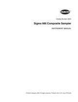
6712 Front Panel

6712SR Refrigerated Sampler
Section 1 Introduction
1-2
The appendices are:
• Appendix A, Menu Flowcharts
• Appendix B, Material Safety Data Sheets
• Appendix C, General Safety Procedures
• Appendix D, Replacement Parts
• Appendix E, Accessories List
1.2 About 700 Series
Modules
The bay on the controller’s side accepts any of Teledyne Isco’s 700
Series Modules. The 700 Series includes:
• 701 pH Parameter Module for monitoring pH and
temperature.
• 710 Ultrasonic Module for monitoring a flow stream’s
level and flow rate with an ultrasonic level sensor.
• 720 Submerged Probe Module for monitoring a flow
stream’s level and flow rate with a submerged probe.
• 730 Bubbler Flow Module for monitoring a flow stream’s
level and flow rate with a bubbler system.
• 750 Area Velocity Module for monitoring a flow stream’s
level, velocity, and flow rate.
• 780 4-20mA Input Module for interfacing to
non-Teledyne Isco devices with 4 to 20 milliampere
output signals.
The modules are optional accessories, and are not required for
operation. However, the modules offer a number of advantages:
they are an economical way to combine flow-rate or parameter
monitoring with sampling, and you can program the samplers
and modules as a single unit. Finally, the samplers store the
readings in memory.
1.3 SDI-12 Sondes As an option, the sampler accepts up to 16 parameters from up to
ten sensors with SDI-12 addresses from 0 - 9 (refer to SDI-12
Sonde Readings, page 1-10, for specific parameters).
The data parameters used by the sensing device (sonde) and
recording device (sampler) must match. Certain vendors’ sondes
have enhanced commands that facilitate “plug and play” setup.
These Teledyne Isco Ready sondes can tell the 6712SR what
values they have, their order, and units of measure. Other sondes
can be used, but require manual setup to identify proper data
types for each data value reported.
1.4 Memory to Store
Monitoring Data
The samplers contain enough memory to store five sampling pro-
grams, sampling data, Teledyne Isco 700 Series Module readings,
and SDI-12 parameter readings. You can view the readings on
your sampler’s display.
You can also retrieve the readings and reports so the information
can be processed on a personal computer. Readings and reports
may be collected with a computer running Teledyne Isco’s
Flowlink™ software. Flowlink can download the information
through a direct connection, a modem connection (when the

6712SR Refrigerated Sampler
Section 1 Introduction
1-3
sampler is equipped with the optional dial-out modem), or from a
581 Rapid Transfer Device (RTD). The RTD is a quick and simple
way to transfer the data from the field to your computer. Reports
are easily collected with Teledyne Isco’s Samplink software.
1.5 Pump Requirements The pump requires a pump tube made specifically for the 6712
and 6700 Series samplers. These pump tubes are easily recog-
nized by their blue alignment collars. The 6712 pump tubing is
the same as that for Teledyne Isco’s 6700 Series samplers, but
different from Teledyne Isco’s earlier model samplers, such as the
3700 Series. Other types of pump tubing will not work in
the 6712SR. Refer to Replacing the Pump Tube on page 8-8.
Table 1-1 6712SR Sampler Features
GENERAL FEATURES
Top Cover
•Protects pump, power source, and controller.
•Lockable latches.
Controller Only
(does not include
refrigerator)
•Contains a rechargeable desiccant to prevent moisture damage to the
electronics, pump, and distributor systems.
•Control panel sloped 15 degrees for easy reading.
•Keys labeled with large, vivid icons.
•80-character display (4 lines by 20 columns).
•Display has selectable backlight:
Always on or always off.
Timed, switching off when keypad is inactive for 60 seconds.
•Memory for program and data storage.
•Flash memory for easy software upgrades.
•NEMA 4X and 6 (IP67) ratings.
Refrigerator
•The 6712SR requires 120 volts AC, 60 Hz, or optional 230 volts Ac, 50 Hz. A
built-in 12 volt DC power converter powers the controller.
•The power supply and solid state thermostat are sealed inside the
refrigerator’s base. However, electrical connections for the fan and
compressor are not sealed.
•A forced air condensing coil and front ventilation let you place the unit close
to a wall or in a corner.
•The oversized wrap-around evaporator plate cools the sampling
compartment quickly and efficiently. Heaters on the plate let the sampler
continue to operate in cold temperatures. The evaporator plate is
self-defrosting.
•Food-grade ABS plastic interior will not support bacterial growth or leach
plasticizers into the sample.
Adjustable
Distributor Arm
•A single distributor arm adjusts quickly to fit all bottle kits. Easily removed
for composite sampling.
Discharge Tube and Support
Spring
•Routes sample liquid from pump tube, through distributor arm to sample bottle.
Composite Tube Guide for
Composite Sampling
•Keeps discharge tube in place over composite bottles.

6712SR Refrigerated Sampler
Section 1 Introduction
1-4
Compatible
Teledyne Isco Products
• 581 Rapid Transfer Device • 1640 Liquid Level Actuator
• 674 Rain Gauge • 2100 Series Flow Modules
• 700 Series Modules • 4100 Series Flow Loggers
• SDI-12 Sondes • 4200 Series Flow Meters
• Refrigerator Temperature Sensor • Flowlink, Samplink
Real-Time Displays As the sampler runs a sampling program, it displays the program’s status.
The status display may include such information as the time of the next
sample, the number of the next bottle, or whether the sampler is disabled or
stopped. If the sampler encounters an error while running the program, it
displays a message alerting you to the problem.
Programming for Modules Program the modules from the sampler’s control panel. The module’s
program settings become part of the sampling program.
Setup for SDI-12 Sondes Calibrate and program SDI-12 sondes from the sampler’s control panel. The
program settings become part of the sampling program. See Section 6.
Memory for Stored Programs
and Readings
512 kilobytes of battery-backed RAM (Random Access Memory), to store:
•Five sampling programs.
•A sampling report from the most recently run program. It records as many as
1000 sampling events; events can be the program start time, enable time,
sample event information, etc.
•700 Series module readings. The readings can be: level, flow rate, velocity, pH,
temperature, or the data collected by the 4-20 mA module.
•Rain gauge and refrigerator temperature readings.
•SDI-12 sonde readings.
Five Reports Available
•The Program Settings report, listing current program settings.
•The Sampling Results report, listing the events occurring during the program.
•The Combined Results report, combining sampling events with readings from a
rain gauge, module, or SDI -12 sonde.
•The Module Summary report, summarizing flow rate or parameter readings.
•The Rainfall Summary report, listing a summary of rainfall readings.
Serial Data Output
ASCII data output from the interrogator port.
Units of Measure A variety of metric and English units of measure for length, flow rate, flow
volume, and temperature.
External Sampler Enable Teledyne Isco flow meters and flow loggers have a programmable sampler
enable feature that lets them send an electronic signal to a 6712SR that
enables (starts) or disables (stops) a running sampling program.
Dual Sampler Mode Dual Sampler Mode operates two samplers.
Command Driven Operation
Operate sampler functions using RS-232 communications.
Warning Messages
•Pump Tube Warning. The 6712SR displays a warning to inspect the tube.
•Internal Battery Warning. From the Maintenance screen, the 6712SR displays a
warning when it is time to replace the internal battery. The internal battery
preserves stored data when the 6712SR is without external power.
Table 1-1 6712SR Sampler Features (Continued)

6712SR Refrigerated Sampler
Section 1 Introduction
1-5
Optional Dialout Modem The 6712 controller can be ordered with a factory-installed 2400 baud dialout
modem. With the modem you can:
•connect to the sampler and download data using Flowlink software.
•program the sampler to call a contact list when an “alarm” condition exists.
•use the Remote Commands to control the sampler’s operation from a remote
location. See Section 5.
On-Line Help Notes When programming the sampler, press the [?] (Help) key for a brief help
note. All help topics appear in the index.
Two Programming Levels Standard programming lets you set up typical sampling programs quickly.
Extended programming includes all features available in standard
programming plus additional features.
SAMPLE DELIVERY SYSTEM FEATURES
Peristaltic Pump
•Benefits: Liquid moves continuously under pumped flow. The pump has no
metering chambers or gravity fed internal tubing to trap sediment or residual
liquid. Sample liquid contacts only the strainer, suction line, tube coupling,
pump tube, bulkhead fitting, and sample bottles.
LD90 Liquid Detector
•Non wetted Detection: Sample liquid never touches the detector.
Two Line Purges in Sampling
Cycle
The sampling cycle always includes a pre-sample purge and post-sample
purge that clears the suction line of residual liquid.
Easy Grab Samples Simply disconnect the pump tube from the bulkhead fitting on the center
section, and place the pump tube over your sample container.
Vinyl and Teflon
®
Suction Lines
•
3
/8-inch ID (Inside Diameter) vinyl line.
•
3
/8-inch ID Teflon
®
lined with polyethylene jacket.
STANDARD PROGRAMMING FEATURES
Pacing
•Uniform Time Pacing: Sampling at regular time intervals.
•Flow Pacing: Sampling at regular flow-volume intervals.
Distribution Methods
•Composite: Samples deposited in a single large bottle.
•Sequential: Only one sample placed in each bottle.
•Samples Per Bottle: Multiple samples placed in each bottle.
•Bottles Per Sample: One sample deposited in multiple bottles.
Three Flexible
Start-Time Settings
•Start Immediately: Starts the sampling program immediately.
•Delayed Start: Starts the sampling program after a user-definable delay
of 1 to 999 minutes.
•Clock Time: Starts the sampling program at a user-definable time on one
or more days of the week.
Option for a Continuous
Running Program
•Continuous Sampling: When sample bottles are regularly replaced, the
sample distribution can restart with the first bottle set after the last bottle
set is filled, without interrupting the running program.
Table 1-1 6712SR Sampler Features (Continued)

6712SR Refrigerated Sampler
Section 1 Introduction
1-6
EXTENDED PROGRAMMING FEATURES
Pacing
•Uniform Time Pacing: Sampling at regular time intervals.
•Nonuniform Time Pacing: Sampling at irregular time intervals.
•Random Interval Pacing: Sampling at unique random time intervals
generated by the controller.
•Flow Pacing: Sampling at regular flow-volume intervals.
•Event Pacing: Sampling each time a user-definable event occurs.
Flow Proportional
Sample Volumes
Allows for sample sizes to be based on flow. (This option is available only
with uniform time pacing.)
Distribution Methods
•Composite: Samples deposited in a single large bottle.
•Sequential: Only one sample placed in each bottle.
•Samples Per Bottle: Multiple samples placed in each bottle
•Bottles Per Sample: One sample deposited in multiple bottles
•Multiple Bottle Compositing: A combination of samples per bottle and
bottles per sample distribution methods.
•Time Switched Bottles or Bottle sets: Control the sample distribution
using clock times.
Programmable Sampler
Enable
A 6712SR sampler can be programmed to enable or disable a running
sampling program when readings received from a connected rain gauge,
module, or SDI-12 Sonde meet certain conditions.
Pauses and Resumes Create intermittent sampling schedules.
Two-Part Programming Two-part programming lets you set up a sampling program that divides the
bottles into two groups, filling each group according to separate pacing,
distribution, sampler enable, and pause and resume settings. This is ideal for
storm-water run-off sampling.
Auto Suction Head or Fixed
Suction Head
The suction head, is the vertical distance from the flow stream to the liquid
detector. Extended programming has two settings.
•Auto-Suction Head: The head is automatically determined.
•Fixed Suction Head: A user-definable measurement for the head.
Suction Line Rinses Program setting for the number of times (0 to 3) that the 6712 rinses the
suction line before drawing a sample.
Sampling Retries Program setting for the number of times (0 to 3) that the 6712 attempts to
sample if it fails to deliver the entire sample volume.
Three Flexible
Start Time Settings
•Run Immediately: Starts the sampling program immediately.
•Delayed Start: Starts the sampling program after a user-definable delay
of 1 to 999 minutes.
•Clock Time: Starts the sampling program at a user-definable time on one
or more days of the week.
Option for a Continuous
Running Program
Continuous Sampling: When sample bottles are regularly replaced, the
sample distribution can restart with the first bottle set after the last bottle
set is filled, without interrupting the running program.
Table 1-1 6712SR Sampler Features (Continued)
/