Page is loading ...


IB 6.1.12.1-1C
2
ABB
TABLE OF CONTENTS
INTRODUCTION .............................................................................................................5
Application ...............................................................................................................................................................5
Designation...............................................................................................................................................................5
Safety Issues .............................................................................................................................................................5
Receiving, Handling, and Storage ..........................................................................................................................5
OPERATING FEATURES AND FUNCTION...................................................................7
Anti-pump Lockout Relay (EO) .............................................................................................................................7
Automatic Spring Discharge (EO) .........................................................................................................................7
Automatic Trip Indicator........................................................................................................................................7
Automatic Trip Alarm Contacts (Optional)..........................................................................................................7
Automatic Trip Lockout (Optional).......................................................................................................................7
Close Button (EO)....................................................................................................................................................7
Close Handle (MO)..................................................................................................................................................7
Close Lever (EO) .....................................................................................................................................................7
Contact Position Indicator......................................................................................................................................7
Lifting Yoke (Optional)...........................................................................................................................................7
Locking Hasp ...........................................................................................................................................................7
Maintenance Handle (EO) ......................................................................................................................................8
Motor Disconnect Switch (EO)...............................................................................................................................8
Nameplate.................................................................................................................................................................8
Racking Mechanism ................................................................................................................................................8
Stored Energy Indicator (EO) ................................................................................................................................8
Trip Buttons .............................................................................................................................................................8
OPERATING DEVICES................................................................................................... 9
Auxiliary Switches ...................................................................................................................................................9
Control Relay Device...............................................................................................................................................9
Magnetic Latch Device............................................................................................................................................9
Shunt Trip Device....................................................................................................................................................9
Overcurrent Trip Devices .......................................................................................................................................9
Electromechanical Overcurrent Trip......................................................................................................................9
Solid-state Overcurrent Trip ..................................................................................................................................9
Microelectronic Overcurrent Trip..........................................................................................................................9
Undervoltage Trip Device (Optional) ..................................................................................................................10
CIRCUIT BREAKER OPERATION ............................................................................... 11
Racking...................................................................................................................................................................11
Courtesy of NationalSwitchgear.com

IB 6.1.12.1-1C
3
ABB
Charging Operation ..............................................................................................................................................11
Electrically Operated Mechanism........................................................................................................................11
Manually Operated Mechanism...........................................................................................................................12
Closing Operation..................................................................................................................................................12
Electrically Operated Mechanism........................................................................................................................12
Manually Operated Mechanism...........................................................................................................................12
Opening Operation ................................................................................................................................................12
Slow-close Procedure.............................................................................................................................................12
Electrically Operated Mechanism........................................................................................................................12
Manually Operated Mechanism...........................................................................................................................13
INSTALLATION AND REMOVAL.................................................................................14
Stationary Type......................................................................................................................................................14
Draw-out Type .......................................................................................................................................................14
MAINTENANCE ............................................................................................................ 15
Inspection ...............................................................................................................................................................15
Arc Chutes ...........................................................................................................................................................15
Contact Structure .................................................................................................................................................16
Control Circuitry..................................................................................................................................................16
Disconnects..........................................................................................................................................................16
Fasteners ..............................................................................................................................................................16
Lubrication...........................................................................................................................................................16
Structural Insulation.............................................................................................................................................17
Setting Adjustments ..............................................................................................................................................17
Contact Structure .................................................................................................................................................17
Control Relay Device ..........................................................................................................................................20
Close Latch Release Rod Travel..........................................................................................................................20
Trip Latch Engagement .......................................................................................................................................20
Tripper Bar Travel ...............................................................................................................................................20
Shunt Trip Device................................................................................................................................................21
Magnetic Latch Device........................................................................................................................................22
Electro-Mechanical Overcurrent Trip Device (OD) ............................................................................................22
Solid-state Overcurrent Trip Device....................................................................................................................23
Microelectronic Overcurrent Trip Device ...........................................................................................................23
Operational Checks ...............................................................................................................................................23
Draw-out Shutter and Racking ............................................................................................................................23
Auto Spring Discharge ........................................................................................................................................23
Electrical Charging, Closing, and Opening .........................................................................................................23
Trip-free Mechanism ...........................................................................................................................................23
Anti-pump Circuit (EO).......................................................................................................................................23
Magnetic Latch Release.......................................................................................................................................23
Trip Latch Drag Force .........................................................................................................................................24
Current Path Resistance.......................................................................................................................................24
Insulation Withstand............................................................................................................................................24
Courtesy of NationalSwitchgear.com

IB 6.1.12.1-1C
4
ABB
Renewal Parts ........................................................................................................................................................24
These instructions do not purport to cover all details or variations or to provide for every possible contingency to be met in connection with
installation, operation, or maintenance. Should further information be desired or should particular problems arise which are not covered
sufficiently for the purchaser's purpose, the matter should be referred to the nearest District Office.
Courtesy of NationalSwitchgear.com

IB 6.1.12.1-1C
5
ABB
INTRODUCTION
Application
This instruction bulletin describes the features,
operation, and maintenance of K-Line circuit breakers
of 225 ampere through 2000 ampere frame sizes.
Familiarize personnel with this bulletin before placing
any circuit breakers into service.
These instructions apply to circuit breakers operated
under the conditions listed in the ANSI Standard
C37.13-1990 Section 2 (Service Conditions).
Abnormal service conditions may require a derating of
the circuit breaker or a modification to its application.
For issues not addressed in this bulletin, contact the
factory as indicated on the rear cover.
Designation
A K-Line type designation identifies the circuit breaker
accordingly by its rated continuous current, form of
overcurrent protection, and physical construction.
Reference the type and design ratings as shown on
the circuit breaker nameplate.
K-Lines are used on AC and DC systems in two and
three pole arrangements. Installation is stationary
(STAT) or draw-out (DO) mounted. The energy
charged in closing springs is either supplied manually
(MO) with a single stroke handle, or electrically (EO)
with a spring charging motor.
Overcurrent protection is available with an
electromechanical (OD), solid-state electronic (Power
Shield), or microelectronic (MPSC-2000) trip system.
ABB trip systems are direct acting; actuating power is
obtained from the protected power system rather than
relying on an external source.
Note: The MPSC-2000 trip device has superceded the
MPS and MPS-C trip devices.
Note: DC service protection is available only with an
electromechanical trip system.
Several combinations of options may be present on a
given circuit breaker. Consult the factory with
questions regarding non-standard options.
Safety Issues
Throughout the manual, there are three terms that
must be heeded, for the following safety reasons:
CAUTION
Not adhering to these instructions may result in equipment
damage or malfunction.
WARNING
Not adhering to these instructions may result in serious injury
and equipment damage.
DANGER
Not adhering to these instructions may result in life threatening
injury and permanent equipment damage.
All circuit breakers have been equipped with safety
interlock systems that must never be defeated:
• Interference Blocking – physically prevents
installation of a breaker into an incompatible
enclosure.
• Racking Shutter – denies racking handle access
to a breaker unless the breaker is both open and
in one of the three racking positions:
CONNECTED, TEST, or DISCONNECTED.
• Automatic Spring Discharge – discharges
charged closing springs if breaker is racked to
the DISCONNECTED position.
Receiving, Handling, and Storage
Upon receiving your order, examine the cartons for
damage sustained during transit. If rough handling is
evident, immediately file a damage claim with the
carrier and promptly notify the ABB District Sales
Office. ABB disclaims responsibility for damages
sustained after delivery to the carrier; however, we will
lend assistance if notified of a claim.
Unpack circuit breakers after receipt. Delayed
unpacking may hamper a claim for damages not
evident upon receipt. Be careful not to inflict damage
while opening the shipment. Compare the carton
contents against the packing list before discarding
packaging. Promptly notify the ABB Sales Office
concerning any discrepancies. Accompany a claim
with purchase order number, carton number, and a
description of damaged or missing parts. Keep the
circuit breaker upright on a flat surface to avoid
damage to breaker parts.
Install circuit breakers in their permanent location as
soon as possible. Until used, the circuit breaker
should be stored and locked in the DISCONNECTED
position inside its compartment with the door closed.
Both the primary and control circuits are disconnected
in this position. Use a lifting yoke for safe and
convenient installation. If the breaker cannot be
installed in its compartment, then seal it in the original
carton to prevent dirt infiltration. Where conditions of
high humidity prevail, the use of heaters is
recommended during storage.
Courtesy of NationalSwitchgear.com

IB 6.1.12.1-1C
6
ABB
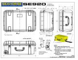
Figure 1d. Primary and Secondary
Disconnects. 1600 Ampere primary
disconnects shown (800 Ampere and
under are typical).
Figure 1c. Escutcheon Panel. Arrangement for an
EO breaker as shown (MO panel is similar).
Ground
Disconnect
Secondary
Disconnect
Primary
Disconnect
Arc Chute
Figure 1a. Type K-1600M Circuit Breaker with Electrically
Operated Mechanism and Draw-out Frame Construction.
Figure 1b. Accessory Racking
and Maintenance Handles.
Racking
Mechanism
Input Drive
(Shutter Closed)
Locking Hasp
Manual Close Lever
(
Mechanical
)
Operations Counter
(
O
p
tional
)
Trip Button
(Mechanical)
Contact Position
Indicator
Circuit Breaker
Nameplate
Close Button
(Electrical)
Trip Button
(Electrical Option)
Auto Trip Indicator
(with optional Lockout
and optional Alarm
Contacts
)
Post Order
Service Decal
Motor
Disconnect
Switch
Stored Energy
Indicator
Accessory Lifting Yoke
Draw-out Arm
Positioning
Pins
Closing Spring
Charging Motor
Control Relay
Device
(
underneath
)
Auxilliary Switch
Bank
Trip Device
(Electronic)
Skirt
Escutcheon
Panel
Interference
Blocking
Figure 1e Disconnects. 2000 Ampere
primary disconnects shown.
Courtesy of NationalSwitchgear.com

IB 6.1.12.1-1C
7
ABB
OPERATING FEATURES AND FUNCTION
The escutcheon panel is the local interface with the
operation of the circuit breaker. On draw-out breakers,
the panel will extend beyond the front door of the
compartment when the breaker is in the TEST and
DISCONNECTED positions.
See the illustrations of Figure 1 for feature location.
Note that not all features are found on a particular
breaker depending on the type designation.
Anti-pump Lockout Relay (EO)
(Not illustrated - internal feature)
The lockout relay functions within the control relay
device. The relay prevents subsequent circuit breaker
closure until the previous close signal is first released
and then reapplied. Anti-pump circuitry prevents
repeated open-close cycling during a trip-free
condition or reclosing onto an automatic trip event.
Automatic Spring Discharge (EO)
(Not illustrated – internal feature)
Electrically operated draw-out breakers are designed
to discharge the closing springs when a breaker is
racked into the DISCONNECTED position. This
internal feature prevents inadvertent breaker closure
while handling the breaker outside of the enclosure.
The spring discharge occurs just before reaching the
DISCONNECTED position. The springs will not store
a new charge until the breaker is moved out of the
DISCONNECTED position.
Note: In early model draw-out breakers [prior 1970],
the closing springs are automatically discharged when
the breaker is pulled to the fully withdrawn position. A
ramp on the cubicle floor drives the close latch
release rod (on the control relay device) as the
breaker is withdrawn from the switchgear.
Automatic Trip Indicator
This is a white indicator marked “RESET”. It is
spring-loaded in the latched position, popping out
upon automatic tripping. The device only indicates
tripping during an automatic event. The cause for
indication should be investigated before resetting the
trip indicator and subsequently re-closing the circuit
breaker. Reset the indicator by physically pushing it
back into its normally latched position. This feature
may be coordinated with a lockout feature.
Automatic Trip Alarm Contacts (Optional)
A microswitch coordinated with the automatic trip
indicator provides remote indication of an automatic
trip event. The trip indicator actuates a roller on the
alarm switch during an overcurrent trip. Resetting the
automatic trip indicator also resets the alarm contacts.
Automatic Trip Lockout (Optional)
Following a fault, the lockout places the circuit breaker
trip-free by holding the tripper bar paddle in the trip
position. The circuit breaker cannot be closed until the
indicator is manually reset on the breaker.
Close Button (EO)
The close push button electrically operates the close
coil (X) in the control relay device. The armature of
this coil actuates the close latch release rod. The rod
actuates the close latches, allowing the closing
springs to operate the breaker mechanism. When no
control power exists, the manual close lever must be
used to close the circuit breaker.
Close Handle (MO)
(Not illustrated)
The T-shaped handle both charges the closing springs
and closes the contacts of a MO circuit breaker in one
sequence. The closing speed is independent of the
handle action. The closing handle also performs the
slow-close operation used for simultaneous contact
adjustment (see Slow-close Procedure).
Close Lever (EO)
The close lever manually closes an EO breaker by
mechanically actuating the close latches. MO breakers
do not have this lever since the mechanism charges
and closes in one operation.
Contact Position Indicator
This mechanical flag indicates the status of the
breaker contacts as either “OPEN” or “CLOSED.”
Lifting Yoke (Optional)
Use a lifting yoke to safely install a breaker into
switchgear. The yoke hooks into the vertical frame
channels as shown in Figure 1a. The bolted
construction allows the yoke to be used for both small
and large frame breakers. If a yoke is unavailable, use
chain hooks in the upper hole of the vertical frame
channels.
Locking Hasp
All K-Line circuit breakers are equipped with a
provision for padlocking the mechanism in an open,
trip-free condition in any of the draw-out positions. The
hasp accepts one or more padlocks. When locked, the
trip-free condition results from the engagement of the
manual trip button linkage.
To lock the breaker open:
1. Trip the breaker open.
2. Depress and hold the mechanical trip button, then
pull the locking hasp outward.
3. Insert lock(s).
When locked, a breaker can neither be racked
between positions nor closed. For EO breakers,
Courtesy of NationalSwitchgear.com

IB 6.1.12.1-1C
8
ABB
attempted closure will only discharge the closing
springs. With MO breakers, the closing handle action
will not engage the closing springs.
Maintenance Handle (EO)
Shown in Figure 1b, the maintenance handle is used
for charging the closing springs of motor-driven
mechanisms when control power is not available. It is
also used for adjusting the simultaneous contact
make during a slow-close operation.
Motor Disconnect Switch (EO)
Used only on electrically charged mechanisms, the
motor disconnect switch (MDS) is wired in series with
the spring charging motor circuit. The switch serves
two functions:
1. Stops the normal sequence of recharging closing
springs following a breaker opening (without de-
energizing the control power source).
2. Isolates the motor from the control wiring when
withstand-voltage testing the control wiring (which
is tested at a higher voltage than the motor itself).
Remember to leave the switch ON after returning a
breaker to service.
Nameplate
The nameplate identifies the rated performance limits
of the circuit breaker as certified per design. Do not
exceed these limits. The nameplate also lists the
circuit breaker model type, frame size, and serial
number. Provide the serial number when contacting
ABB for information.
Racking Mechanism
Utilize a racking handle, as shown in Figure 1b, to
operate the racking mechanism of draw-out circuit
breakers. The racking mechanism moves a draw-out
type circuit breaker between any of three positions:
CONNECTED, TEST, or DISCONNECTED. Position
is indicated by a decal in two places: the left upper
cradle arm (open cubicle door) and on the escutcheon
box right-side (closed cubicle door). The racking
shutter is interlocked with the position of the breaker
contacts to deny handle insertion unless the breaker
is open. Additionally, the circuit breaker is trip-free
between racking positions.
Stored Energy Indicator (EO)
This mechanical flag indicates the stored energy
condition of the closing springs. The two states of the
flag are marked "SPRINGS CHARGED" and
"SPRINGS DISCHARGED."
Trip Buttons
All breakers have a mechanical push button trip for
opening the breaker locally. A second optional trip
button electrically operates the shunt trip for locally
opening the breaker.
Courtesy of NationalSwitchgear.com

IB 6.1.12.1-1C
9
ABB
OPERATING DEVICES
Auxiliary Switches
The switches are furnished in 4 or 8 contact banks.
With the opening and closing of the breaker, a
jackshaft driven linkage operates the rotary switch
contacts between the open and closed position. By
designation, “a” contacts are synchronized with the
breaker contact position (normally open when the
breaker is open). The "b" contacts are arranged
oppositely (closed when the breaker is open). If
desired, an “a” contact can be made into a “b” contact
(and vice versa) by opening the switch and rotating
the contact element 90°.
Control Relay Device
A control relay device is furnished on EO circuit
breakers. The electromechanical device mounts to the
left bottom edge of the mechanism front cover. Three
electrical components are housed:
1. Limit Switch, “LS” – Cycles the closing spring
motor power.
2. Lockout Relay, “Y” – Actuates the anti-pump
circuitry.
3. Latch Release Relay, “X” – Operates the close
latch release rod.
The device base also serves as a terminal block for
much of the circuit breaker wiring. Reference Table
A2 of Appendix A for applicable control
characteristics. Reference Figure A1 of Appendix A
for a control wiring schematic.
Magnetic Latch Device
The magnetic latch device receives a trip signal from
the electronic trip unit. A permanent magnet latches
the device plunger against a compressed spring.
When energized by a trip signal, the device coil
momentarily cancels the magnet’s field, releasing the
plunger and opening the circuit breaker.
Shunt Trip Device
The shunt trip is employed for opening the breaker on
command. It is energized remotely through the
secondary disconnect contacts or locally with the
optional electric push trip button. When energized, the
shunt trip coil actuates the device trip rod, which
strikes the trip latch, opening the breaker. Reference
Table A2 of Appendix A for applicable control
characteristics.
Overcurrent Trip Devices
All overcurrent trip devices must be uniquely
coordinated to the system for which the breaker is
intended to protect. Use appropriate trip settings and
reference the pertinent time-current curves for delay
times. The time delay will fall within the limits of the
graphed time bands, subject to the notes therein.
The tolerance for a trip event at a pickup setting is:
• Long-time: ± 10%
• Short-time: ± 15%
• Instantaneous: ± 20%
• Ground: ± 15% (not available with OD)
Refer to Tables B1, B2, B3, and B4 of Appendix B for
standard device types, testing, and applicable time-
current curve references. For non-standard trip
devices not listed, consult ABB.
Electromechanical Overcurrent Trip
These devices are commonly referred to as “OD” (oil
displacement) devices because many have a long-
time delay element that utilizes a dashpot. The
device consists of a primary current coil assembly,
laminated iron circuit, and mechanical parts that
actuate the calibrated device. The coil assembly
mounts in series with the current path of each phase.
Magnetic flux develops in the iron circuit and across
an air gap at one end of a pivoting leg. Each trip
element: long-time, short-time, and instantaneous
has an adjustable tripping current level (pickup). At
the currents marked on the nameplate, the device is
calibrated to “pick up” the open pivoting leg. The
resulting motion trips the breaker through tripper bar
actuation. Tripping is delayed by dashpot oil
displacement for long-time overcurrent events. A
mechanical gearbox delays tripping for short-time
overcurrent events. No intentional delay was
designed for instantaneous overcurrent events.
Solid-state Overcurrent Trip
The Power Shield
solid-state overcurrent trip
system uses analog circuitry to monitor system
power. Each breaker phase has two sensors: a
power sensor to supply the trip system and a current
sensor for producing current proportional to the
primary circuit. During an automatic trip event, the
trip device signals the magnetic latch to open the
circuit breaker.
In addition to long-time, short-time, and
instantaneous protection, the introduction of a solid-
state trip device made ground fault protection
available. The functions have selectable time delay
and tripping thresholds. Combinations of tripping
elements are specific to the device type.
Microelectronic Overcurrent Trip
The Micro Power Shield
designs employ digital
circuitry and software driven microelectronics to
protect system power. Having a similar physical
arrangement and function as the solid-state trip
system, the microelectronic trip systems use one
sensor to both power the trip system and provide a
Courtesy of NationalSwitchgear.com

IB 6.1.12.1-1C
1
0
ABB
current signal for fault monitoring. Systems with
communications ability also offer voltage, current,
and power imbalance information.
MPS (Discontinued)
The first of the microelectronic systems, protection
settings were made with switches on the face of the
device. Combinations of long-time, short-time,
instantaneous, and ground trip events were specific
to each device type.
MPS-C (Discontinued)
The MPS-C incorporated a communications interface
with the MPS device. A Network Interface Module is
needed to communicate with the trip device. Like the
MPS trip system, permutations of long-time, short-
time, instantaneous, and ground trip events were
specific to each device type.
MPSC-2000
The MPSC-2000 combined all tripping elements in
one device. Instantaneous or short-time (not both
together), ground, and I
2
t elements are defeatable to
obtain desired coordination. Instead of mechanical
switches, the MPSC-2000 utilizes a LCD for device
interface. Menus allow the user to view real-time
metering information, review protection settings,
modify protection settings with password
authorization, and review operational history. Fault
event history and device settings are recorded in
non-volatile EPROM memory.
MPS-C and MPSC-2000 units can be tested with the
BTSB (Bench-top Trip Simulator for Breakers) both
on and off the breaker. Tested on the breaker, the
BTSB can also operate the magnetic latch as part of
the fault simulation. When testing the MPS-C, the
BTSB interactively guides the user through the test
sequence. When testing the MPSC-2000, the BTSB
runs all tests unassisted and restores the original
settings after test. Results are stored in non-volatile
memory and may be reviewed on-screen or sent to a
printer. The test set also has a port for downloading
future software upgrades.
Undervoltage Trip Device (Optional)
The undervoltage trip device automatically trips the
circuit breaker when the supplied voltage decreases
to between 30% and 60% of the rated voltage. The
device resets when the supplied voltage restores to
80% of its nominal value. This device can be
furnished either for instantaneous trip operation or
with an adjustable time delay, actuating between 1.5
to 15 seconds.
The device coils normally operate continuously to
keep the device armature picked-up. Following
undervoltage drop-out, the breaker remains trip-free
until voltage is restored and the device picks-up
again. Undervoltage devices normally open a
breaker through tripper bar actuation, but may be
configured (non-standard) to trip the latch directly.
Refer to Table A3 of Appendix A for device
characteristics.
Courtesy of NationalSwitchgear.com

IB 6.1.12.1-1C
1
1
ABB
CIRCUIT BREAKER OPERATION
In principle, all K-Line circuit breakers cycle through
three stages of operation: charging, closing, and
opening. The charging and closing stages differ
between MO and EO mechanisms in that a MO
mechanism does not intermediately store charged
closing spring energy.
Racking
Draw-out breakers are racked between positions of
DISCONNECTED, TEST, and CONNECTED.
Reference the decal either on the escutcheon box
right-side (door closed) or on the left cradle arm (door
open). Using the decal as a reference, the breaker is
properly in position when the racking shutter closes
after handle removal.
Within the breaker, an index cam interlocks the
racking mechanism with the breaker contact position.
The shutter prohibits racking handle access to the
drive input until the breaker is opened. Additionally,
the shutter must fully close in each position, because
the interlocking places the mechanism trip-free
between draw-out positions. For EO breakers,
attempted closure will discharge the charged closing
springs without driving the breaker mechanism. With
MO breakers, the closing handle will not even engage
the closing springs. The interlocking prevents
connecting or disconnecting a closed breaker with an
energized circuit.
Placing a draw-out breaker into service:
1. Open the breaker.
2. With the breaker mounted on extended rails, turn
the racking handle fully CCW (counter-clockwise).
Push the breaker into the cubicle. The draw-out
arm roller on both sides of the breaker engages
with the track of the cradle.
3. Turn the racking handle CW (clockwise); placing
the breaker into the TEST position. Make pre-
operative checks.
4. Completely turn the handle CW until the racking
mechanism stops, placing the breaker in the
CONNECTED position. A momentary resistance
to motion will be noticed as the spring-loaded
disconnects engage the cubicle stabs.
Removing a draw-out breaker from service:
1. Place the motor disconnect switch (if equipped) in
the OFF position to prevent subsequent closing
spring recharging after breaker opening. Open the
breaker.
2. Rotate the handle CCW, placing the breaker in
the TEST position.
3. Rack fully CCW into the DISCONNECTED
position. If the closing springs are charged, the
automatic spring discharge feature will discharge
the charged closing springs within the last few
turns of the handle.
Charging Operation
The potential energy of charged closing springs close
the circuit breaker contacts. Electrically operated
mechanisms store spring energy until triggered to
close. Manually operated breakers both charge and
close in one sequence.
Electrically Operated Mechanism
The charging motor charges the closing springs.
Under a normal wiring configuration as illustrated in
Figure A1 of Appendix A, the motor will charge the
closing springs of an open breaker having control
power, unless the MDS is positioned OFF. The closing
springs discharge in the process of closing the circuit
breaker. Upon closing, the L/b contact at terminals 1
and 2 opens, preventing power to the motor through
the closed LS/1 charging spring limit switch. Upon
opening, the L/b contact closes and the breaker
immediately recharges its closing springs for re-
closure. Some charging circuits are configured without
the auxiliary switch contact L/b at terminals 1 and 2, in
which case the charging springs immediately recharge
after closing the circuit breaker. An anti-pump relay
within the control relay device prevents repetitive
breaker closure if a close input is maintained during a
trip-free condition.
CAUTION
Do not forget to leave the motor disconnect switch ON after
maintenance, else the breaker cannot be charged electrically
for subsequent closure.
Use the Maintenance Handle accessory to manually
charge the closing springs when control power for the
Figure 2. Maintenance Handle Engagement.
Courtesy of NationalSwitchgear.com

IB 6.1.12.1-1C
1
2
ABB
motor is unavailable. Engage the handle with the drive
carrier as demonstrated in Figure 2. Charge springs
by ratcheting the carrier with a smooth, deliberate
motion. Charge until a latching sound is heard as the
closing springs snap over-center. At this point, the
carrier no longer engages teeth of the driven gear and
the stored energy indicator will display “SPRINGS
CHARGED”.
The loaded action of the drive carrier occasionally
back-drives the motor crank arm into a position that
holds the carrier at partial stroke. The crank arm must
be physically rotated to allow the carrier to cycle and
engage the next tooth of the charging gear. With
Ametek motors, this can be accomplished by forcing
the carrier upward against the resistance of the motor
gearing. Because of the higher gearing torque of the
Ryobi charging motor, resetting the carrier is most
easily accomplished by rotating the motor armature.
DANGER
The motor must be isolated from control power before
attempting to turn the armature. Beware of a hot commutator if
the motor was just operated. Do the following:
• Rack the circuit breaker to the DISCONNECTED position
to isolate it from the control circuit. (Stationary breakers
must have the control circuit de-energized).
• Wearing a glove (measure of safety), rotate the armature
by turning it at the exposed commutator.
Manually Operated Mechanism
Circuit breakers with a MO mechanism are operated
with the T-shaped closing handle. The mechanism
closes the breaker independent of handle operating
speed. In one operation, the closing springs both
charge and then discharge to close the breaker
without an intermediate stored energy condition.
Manually operated mechanisms therefore do not have
a close control circuit, close latching, or an automatic
spring discharge feature.
Closing Operation
Electrically Operated Mechanism
The energy of discharged closing springs drives the
breaker mechanism to close the breaker contacts.
Closure is initiated locally at the escutcheon panel or
remotely by electrical means.
Standard equipment allows closing at the escutcheon
panel using either the mechanical close lever or the
electrical push button close. The close button
actuates the release (close) coil in the control relay
device. Remote closure uses the same release coil
circuit.
Manually Operated Mechanism
Manually operated breakers are closed at the end of
the charging cycle during the continuous handle
motion described in the charging section.
Opening Operation
The loaded contact springs and two charged opening
springs provide the energy for opening the circuit
breaker. Opening is either manual or automatic.
Manual opening is performed locally with the
mechanical push button trip or the optional push
button electric trip. The push button electric trip
actuates the shunt trip device. Remote opening uses
the same shunt trip circuit. Automatic tripping is
initiated with an overcurrent or undervoltage device.
As visualized in Figure 8, depending on the mode of
circuit breaker opening, the secondary trip latch
operates either independently or dependently with
the tripper bar. Shunt tripping and mechanical push
button tripping operate the latch directly without
using the tripper bar. Overcurrent and undervoltage
devices actuate the tripper bar, which in turn rotates
the secondary trip latch. This distinction
discriminates between an intentional opening and an
automatic trip event because the tripper bar also
actuates the automatic trip indicator.
Slow-close Procedure
The purpose of the slow-close procedure is for
checking the travel of the contact assemblies and
adjusting the simultaneous-make between poles.
WARNING
The circuit breaker should be clamped down during the slow-
close procedure to keep it from tilting while manually charging
the closing springs.
Electrically Operated Mechanism
CAUTION
The charging cranks must be reset after the last slow-close
operation or future electrical operation will be impossible (see
steps #8, #9 and #10 below).
1. Charge the closing springs electrically or manually
and observe the closing spring charge indicator.
Turn off the motor disconnect switch.
2. Referencing Figure 3, insert a screwdriver through
the hole in the escutcheon box and depress the
close block pin lever downward.
3. With the close block pin lever held in the down
position, initiate closure with the manual close
lever. Instead of the breaker closing, the spring
load transfers to the close block. The close block
pin lever will remain in the down position.
4. Insert the maintenance handle in the motor drive
carrier as shown in Figure 2. Slowly close the
breaker contacts by actuating the handle.
To repeat the slow-close operation, continue with the
following steps:
5. Re-insert the maintenance handle and complete
the charging cycle until the indicator shows
"SPRlNGS CHARGED" (may already be the case
as in step #4).
Courtesy of NationalSwitchgear.com

IB 6.1.12.1-1C
1
3
ABB
6. Open the breaker with the manual trip button.
7. Resume slow closing with steps #2, #3, and #4.
Referring to the previous warning, reset the charging
cranks for normal electrical operation as follows:
8. Repeat previous steps #5 and #6.
9. Lift manual close lever to close the contacts.
10. Push the manual trip button to open the contacts.
The closing springs are now discharged with the
charging cranks reset. Restore power to the charging
motor with the MDS in the ON position. The
mechanism is ready for electrical operation.
Manually Operated Mechanism
1. On 1600 and 2000 ampere breakers, at each of
the two spring guards, loosely install 1/4” diameter
pins or machine screws as shown in Figure 4 (not
necessary for 800 A and under frame sizes).
2. Insert a screwdriver through the hole in the
escutcheon box and mechanism housing
assembly (right-hand side when facing the front of
the circuit breaker.)
3. Using the top of the hole as the fulcrum and a
screwdriver or rod as a lever, depress the hold-up
latch. At the same time, pull the operating handle
forward enough to engage the slow-close latching,
then work the handle in one stroke to move the
contacts through the open-to-close range.
WARNING
Keep a firm grip of the handle, which is loaded with the energy
of the mechanism when slow closing.
4. Remove the two 1/4” diameter pins or machine
screws installed in step #1 after the slow-close
operation is complete, else the mechanism cannot
be charged and closed in the normal operating
mode.
Note: The step #1 operation, as illustrated in Figure
4, is not necessary for adjusting the simultaneous-
make. However, without the temporary pins, the
breaker will not latch closed.
Figure 4. Temporary Screws. Installed for
slow-close latching 1600 and 2000 frame
size MO breakers.
Figure 3. Slow-close Lever on EO
breakers. Located on the escutcheon box
right-side. Depress lever with a screwdriver.
Figure 5. Slow-close Lever on MO
breakers. Located on the escutcheon box
right-side. Depress lever with a screwdriver.
Courtesy of NationalSwitchgear.com

IB 6.1.12.1-1C
1
4
ABB
INSTALLATION AND REMOVAL
NOTE: If a breaker with OD devices has been
shipped or stored on its back, then oil in the dashpot
might have been displaced and an air bubble trapped
under the piston. Before installing the breaker, with
the breaker in the upright position, exercise the long-
time armature of each breaker phase (the 5/8” wide
armature) several times until resistance to motion has
increased. Resistance indicates that air entrapment
has cleared and the oil dashpot is functioning
properly.
CAUTION
Do not lift the breaker by the primary disconnects. Use a chain
and hooks in the top hole of the vertical frame channels or a
lifting yoke. Be careful not to damage the disconnects when
installing or removing a breaker in the switchgear.
Stationary Type
DANGER
When installing or removing stationary breakers, the supply for
primary and control circuits must be de-energized at all times.
Testing of stationary circuit breakers must be done with the
primary supply circuit de-energized.
A lifting yoke should be used to move the breaker to
the switchboard. Other handling means may be
required to move the breaker into position inside the
switchboard.
Draw-out Type
When moving between positions, confirm that the
racking shutter closes fully after removing the handle.
If it closed partially, then the breaker is not yet fully in
position.
For initial installation of draw-out breakers into the
CONNECTED position, the supply for the primary
circuit should be de-energized (even though the
breaker will be open). Perform any operational tests in
the TEST position.
Proceed as follows to install and connect a circuit
breaker in its compartment:
1. The circuit breaker must be in the open position,
the racking mechanism cranked fully in the CCW
direction against its stop, and the motor disconnect
switch (EO circuit breakers) in the OFF position.
2. Open the compartment door and pull out the right-
hand and left-hand cradle rail to the fully extended
and latched position.
3. Using a lifting yoke, lower the circuit breaker so
that the positioning pins, two on each side of
breaker, rest in the cut-out sections of each rail.
4. Remove the lifting yoke and push the circuit
breaker toward the compartment. The breaker will
slide on its positioning pins to the rear of the cut-
out sections in the rails. An additional push will
overcome the two cradle latches allowing the
circuit breaker to move into the DISCONNECTED
position. The draw-out arm of both sides will make
initial cradle engagement.
5. Lift the racking shutter, insert the racking handle,
and crank CW. Rack from the DISCONNECTED
position into the TEST position. Make operational
checks as described in the Maintenance Section
before placing the breaker in the CONNECTED
position for online service.
Proceed as follows to rack a CONNECTED circuit
breaker into the TEST position:
1. With the compartment door closed, trip the circuit
breaker open.
2. Lift the racking shutter and insert the racking
handle. Rack CCW until the decal on the right-
hand side of the escutcheon indicates the TEST
position. NOTE: This position was designed for
making operational checks. The control circuit is
energized, but the primary disconnects are not
connected.
Proceed as follows to disconnect and remove a circuit
breaker from its compartment:
1. Turn the motor disconnect switch OFF. If closed,
open the breaker. Draw-out CCW until the racking
mechanism reaches its stop. If the mechanism is
charged, expect an automatic spring discharge just
before reaching the fully DISCONNECTED
position (EO breakers).
2. Pull the circuit breaker forward until both cubicle
rails are in the fully extended and latched position.
3. Position a lifting yoke. To keep the yoke hooked
into the breaker, partially lift the circuit breaker
weight.
4. With a positive pull, slide the breaker forward on its
positioning pins in the track of both rails. Notice
that the track for the positioning pins has a locking
action in both ends of the cut-out. If the breaker is
slid too far forward, it will remain secured in the
rails.
5. Lift the circuit breaker from the rails.
6. Release the latch on each rail and push the rails
back into the compartment. Keep the compartment
door closed.
Courtesy of NationalSwitchgear.com

IB 6.1.12.1-1C
1
5
ABB
MAINTENANCE
This section provides guidelines applicable under the
normal operating conditions referenced in the
Introductory section. Where unusual service
conditions exist, ABB presumes that these conditions
were considered at the time of order, the equipment
supplied was designed for the special application, and
an appropriate supplemental maintenance program
had been developed.
Maintenance frequency should be based on factors
that influence the circuit breaker operating condition
over a period of service. The operating condition is
predominantly a function of the circuit duty and the
circuit breaker environment. The merit of a
maintenance schedule should be based on service
records specific to the breaker’s application. ABB
recommends the schedule shown in Table 1 until a
service history is established for the circuit breaker.
Perform maintenance before the number of
operations or time elapsed since the last maintenance
interval, whichever comes first. This schedule may be
altered at the user’s discretion based on actual
performance. On a new circuit breaker, ABB
recommends inspection within the first year of service,
regardless of the number of operations.
In addition to Table 1, inspect a breaker after short-
circuit interruption as soon as possible. Examine the
arc chutes, the condition of the contacts, and check
the contact pressure before continued service.
ABB recommends circuit breaker refurbishment when
the circuit breaker achieves its designed mechanical
endurance limit or the period of service as shown in
Table 2
Table 2. Full Refurbishment Schedule
Frame Size
Total
Operations
Service Period
(Years)
225, 600, & 800 12,500 10
1600 & 2000 4000 10
Maintenance programs should consist of inspection,
cleaning, adjustments, and operational checks as
recommended or when affected by other adjustments.
Adjustment is not required for most devices unless
removal of another device so affects it.
DANGER
Beware of electrical hazards. Remove a circuit breaker from
service (CONNECTED) before attempting any maintenance
activities. Draw-out circuit breakers must be withdrawn to the
TEST position before any operational checks and withdrawn
from the cubicle for inspection, adjustment, or repair.
Stationary breakers must be de-energized from the primary
circuit before any operational testing and also from the control
circuit before any inspections or repair.
WARNING
Beware of mechanical hazards. Stay clear of moving parts and
take precaution with the use of tools when operating the circuit
breaker. Notice whether or not the breaker is open or closed by
observing the contact position indicator. Check the charge
status of the closing springs by observing the stored energy
indicator. A charged breaker has the potential to inadvertently
close; likewise, a closed breaker may surprisingly open.
WARNING
Do not work on a draw-out circuit breaker withdrawn on
extended cubicle rails.
To minimize down-time, stock commonly needed
spare parts as suggested in the Renewal Parts
section.
Inspection
Inspect the general condition of the breaker and
enclosure. Initial observations are worth recording for
subsequent troubleshooting and a general feel for the
adequacy of the maintenance program. Inspect the
enclosure floor for broken hardware or fallen parts.
After initial assessment within the enclosure, rack the
circuit breaker out for further inspection.
Arc Chutes
The chutes are secured with a screw and a poly-glass
retainer as mounted between the poles. Check the
Table 1. Maintenance Schedule Based on Circuit Duty and Circuit Breaker Environment.
Load Current Switching
(Duty ≤ Continuous Current Rating)
Motor Starting or
Capacitor and Reactor
Switching
Clean Environment Typical Environment Any Environment
Frame Size
Operations Years Operations Years Operations Years
225, 600, & 800 1750 5 1000 3 1000 3
1600 & 2000 500 5 300 3 300 3
Courtesy of NationalSwitchgear.com

IB 6.1.12.1-1C
1
6
ABB
tightness of these retainers at the recommended
maintenance intervals. Install chutes as follows:
1. Remove the electronic trip unit to access the
retaining hardware (if applicable).
2. Remove the screws and retainers. Tilt each arc
chute forward at the top and lift to remove.
3. Install in reverse order. Do not overtighten the
screws to avoid breaking the retainer or chutes.
Tighten screws to a maximum of:
Frame Size Maximum Torque
225, 600, & 800 35 lb-in
1600 & 2000 75 lb-in
Look at the damage that service has impacted on the
chutes. Examine the arc chute exterior and the arcing
chamber. Soot, uniform erosion, and discoloration are
normal observations associated with arcing.
Replace a chute when any:
• The stationary arc runner has significant erosion.
• Arc splitters have burn-through holes.
• Moldings have broken functional features that
retain arc splitters or baffle parts.
• Shell moldings have mating surface defects that
may allow interruting gases to escape (flashover
potential).
Clean outside shell and arcing chamber region with a
clean cloth and denatured alcohol.
Contact Structure
Examine contact members for cracks and erosion.
Replace members with body cracks or broken
sintered contacts. Consider replacement of an arcing
contact member when the thickness of the sintered
arcing material has eroded to less than 50% of its
new thickness. Replace a main contact member if it
has erosion that cannot be dressed sufficiently to re-
establish a smooth surface. Likewise, inspect the
condition of the stationary contacts for erosion.
Check the mating primary disconnect surface of the
terminal studs for signs of burning.
If contacts need conditioning:
1. Avoid getting debris into the mechanism during
the cleaning and dressing process.
2. Remove bulk residue on contacts with a lint-free
cloth. Remove small burrs on contacts by filing
along the contour of the contact. Clean with
denatured alcohol.
3. Re-establish proper contact pressure and
simultaneous-make.
Control Circuitry
Inspect wiring for damaged insulation. Clean any
grease from the insulation. Check that wire routings
are protected from sharp edges. Confirm that lugs
and terminals are securely fastened. Confirm correct
wiring with preoperative checks that use the
connected device. If an electrical malfunction is
detected, compare the physical wiring configuration
against the schematic diagram of Figure A1 of
Appendix A. Test dielectric integrity with a Withstand-
Voltage Test as outlined in the Insulation Withstand
section.
Disconnects
Inspect the primary disconnects for corrosion and
signs of over-heating. Remove the old NO-OX-ID “A-
Special” grease using a petroleum solvent (as
suggested by Sanchem) followed by a clean cloth
and denatured alcohol. Confirm that assemblies
were not damaged while servicing the breaker.
Reapply the NO-OX-ID “A-Special” only to the
switchgear end of the primary disconnect assemblies
where sliding contact occurs.
Inspect the secondary assemblies for a broken
plastic housing. Wipe clean, but do not lubricate the
secondary disconnect contacts. Identification of the
contacts can be determined from Figure A2 of
Appendix A.
Fasteners
Check the circuit breaker for loose, broken, or missing
fasteners. Locking type fasteners should be replaced
when removed. Torque hardware when indicated in
the bulletin.
Lubrication
Inspect existing grease to determine whether it should
be replaced. Discolored grease indicates oxidation
and contamination. Dry, caked grease has no
lubricating qualities and must be replaced.
As supported by service history and periodic
endurance testing, use only the greases approved by
ABB for use in K-Line circuit breakers. The approved
greases and application are as follows:
1. NO-OX-ID “A-Special” grease manufactured by
Sanchem, Inc. is a corrosion and water inhibitive
coating applied to the mating and working
surfaces of primary current path parts. Maintain
application on the primary disconnects, contact
structures, and any other primary current path
parts during maintenance intervals. Do not apply
NO-OX-ID “A-Special” to any secondary circuitry.
CAUTION
Do not apply NO-OX-ID grease on the parting surfaces of the
main or arcing contacts; may increase the interface resistance,
as well as, collect contaminating debris. The wiping action and
contact pressure were designed to maintain the interface.
2. Anderol 757 synthetic grease manufactured by
Huls America, Inc. is applied to moving surfaces
and for packing bearings.
Courtesy of NationalSwitchgear.com

IB 6.1.12.1-1C
1
7
ABB
3. Mobil 28 grease as an alternative to Anderol 757
(for refurbishment only). ABB strongly
recommends using only one type of grease
throughout the breaker.
CAUTION
Anderol 757 and Mobil 28 are substantially incompatible
greases. Before relubricating parts with either grease,
thoroughly remove the existing lubricant. Furthermore, parts
ordered for replacement are lubricated with Anderol 757, which
must be removed before use with Mobil 28 lubricant.
CAUTION
Do not apply grease to the latching or roller surfaces of either
the primary or secondary trip latches. The working surfaces
were designed without grease that will otherwise collect
debris.
When operated by the schedule of Table 1, K-Line
circuit breakers should not need renewed application
of grease to parts between scheduled maintenance
intervals. Reapply grease when parts are removed,
replaced, or cleaned. Wipe away excess grease
outside of working surfaces. If the service
environment has unduly contaminated the lubricant,
then cleaning and reapplication may be necessary.
Proper re-lubrication requires disassembly and
thorough cleaning before applying new grease.
Thoroughly wash used bearings to remove old
lubricant or debris. Thoroughly wash new bearings to
remove the packaged grease, which may be
incompatible with the grease applied. Dry bearings
before packing with fresh grease.
Do not apply any lubrication to cadmium plated
current path parts of special cadmium plated
breakers.
CAUTION
When mechanism cleaning and re-lubrication is required, do
not use solvents. Solvents introduce foreign debris into
bearings, strip remaining lubricant from working surfaces, and
can leave a binding residue. A mechanism with contaminated
grease should be completely refurbished.
CAUTION
DO NOT apply light machine oil or thin spray lubricants to
lubricate any mechanism part.
CAUTION
DO NOT attempt to re-lubricate the spring charging motor
gearbox; it is sealed and should not require re-packing.
CAUTION
DO NOT lubricate, clean, or spray the magnetic latch device
with any substance.
Structural Insulation
Insulated parts should be checked for damage. Glass-
polyester insulation may be cleaned with a clean cloth
and denatured alcohol. While cleaning parts, avoid
getting alcohol on points of lubrication. Test the
insulation dielectric as described in the Insulation
Withstand section.
Setting Adjustments
The breaker control devices utilize self-locking
hardware that should not be routinely adjusted;
otherwise, the locking feature becomes increasingly
compromised.
Device settings are factory established and will not
normally need subsequent readjustment unless the
device is malfunctioning, removed, replaced, or
indirectly affected by other device adjustments.
Several device settings work dependently on the latch
and tripper bar. Should the latch engagement or
tripper bar travel be adjusted, reestablish the setting of
all affected devices.
Contact Structure
Contact structure adjustment is a routine maintenance
item and must be checked at every service interval.
Contact adjustment is an iterative process of both
pressure and simultaneous-make adjustments. The
measurement may vary slightly each time that it is
checked. Avoid undue “searching” which will wear the
locking material of the adjustment stud. If an adjusting
stud appears not to hold the contact pressure setting
while making operational checks, then apply “blue”
Loctite to the threads and consider replacing the part.
Adjust pressure accordingly by turning the adjustment
screw in the direction shown in Figure 6d.
Perform any contact structure adjustment as described
in the Slow-close Procedure section.
CAUTION
The contacts are set on a closed breaker. Keep clear of
potential moving parts should you inadvertently trip the
breaker during adjustment.
225 Ampere Frames
1. Same as step #1 for the 600 and 800 ampere
frames.
2. Contact pressure is established by adjusting the
stud for 1-3/4” ± 1/32” open-air gap as
dimensioned at A in Figure 6a. Any adjustment of
contact pressure must be followed by the
simultaneous-make adjustment in step #3.
3. Same as step #3 for the 600 and 800 ampere
frames.
If for any reason the contact structure is removed from
the breaker, upon assembly, reapply clean NO-OX-ID
“A-Special” to the ends of the contact bushing. Torque
the hinge-joint nut between 15 and 25 lb-ft to maintain
the continuous current rating of the circuit breaker.
Courtesy of NationalSwitchgear.com

IB 6.1.12.1-1C
1
8
ABB
600 and 800 Ampere Frames
(K-600, K-800, K-600S, K-800S, and K-800M)
1. The hex portion of the adjustment stud must be
centered within 1/16” between the yoke and the
pushrod insulator.
2. Contact pressure is established on a closed
breaker with the adjustment stud for a 5/64” to
3/32” gap at A in the upper window of the contact
carrier on each side as shown in Figure 6b. The
most proficient way is to slide 5/64” and 3/32”
diameter wires (go and no-go) bent at 90° up and
down in the slot. Close the circuit breaker. Using
the side with the larger gap, set the gap to accept
the “Go” gauge but reject the “No-Go” gauge.
Open and again slow-close the circuit breaker to
recheck the pressure. Follow each adjustment of
contact pressure by a making adjustment in step
#3. After completing step #3, the adjusted poles
may have a pressure setting greater than 3/32”;
this results in more contact pressure on these
poles, which is acceptable.
3. Slow-close the contact structure until the arcing
contacts of one pole just touch. At this point, the
arcing contacts of the other two poles should be within
1/32” of touching (same idea for a two pole breaker).
If not within 1/32”, then turn the adjustment stud of
these two poles in the direction to increase pressure
until all three poles touch within 1/32”. Should the
pressure be too excessive to allow the breaker to
latch closed, return to the first making pole, decrease
its pressure by 1/8 revolution (CW), and recheck the
simultaneous-make. Repeat in increments of about
1/8 revolution for no more than 1/2 revolution of the
adjusting stud on the first make pole, until the breaker
latches closed.
If for any reason the contact structure is removed from
the breaker, upon assembly, reapply clean NO-OX-ID
“A-Special” to the ends of the contact bushing. Torque
the nut of the hinge joint between 15 and 25 lb-ft to
maintain the continuous current rating of the circuit
breaker.
1600 A and 2000 A Circuit Breakers
(K-1600, K2000, K1600S, K2000S, K-1600M, and
K2000M)
The main contact adjustment is to be made with the
breaker in the latched closed position. Contact
pressure is established by turning the adjustment stud
until a go-gauge will just fit the space A at the rear of
the moving main contacts as illustrated in Figure 6c.
Set at 3/4” [+0”, -1/64”].
After making this adjustment in contact pressure,
open the circuit breaker, re-close the circuit breaker
normally, and recheck the gap A. Readjust if
necessary.
Open the circuit breaker and slow-close the contacts
until the arcing contacts of one pole just touch. The
remaining poles should then be adjusted for
simultaneous-make by advancing the adjustment stud
until all poles touch within 1/32” of one another. The
contact pressure will increase on the adjusted poles
as evidenced by a pressure setting of less than 3/4”;
this results in more contact pressure on these poles,
which is acceptable.
For 2000 ampere breakers (tulip style primary
disconnects), if the primary disconnect stud is
removed, retorque the stud to 110 lb-ft.
Courtesy of NationalSwitchgear.com

IB 6.1.12.1-1C
1
9
ABB
A
Torque
Hinge Joint
Contact Pressure
Adjustment Gap
Transfer Contact
Member
Pushrod
Insulator
Yoke
A
Contact Pressure
Adjustment Gap
Torque
Hinge Joint
Arc Runner
Assy
Moving Arc
Contact Member
Adjustment
Stud
Upper Terminal
Current Studs
(Upper & Lower
Halves)
Moving Main
Contact Member
Upper Terminal
(stab portion)
Stationary Arc
Contact Member
Moving Arc
Contact Member
A
Adjustment Stud
Arc Runner Assy
Moving Main
Contact Member
Stationary Main Contact
(Upper Terminal)
Stationary Main Contact
(Lower Terminal)
Contact Pressure
Increase
Contact Pressure
Decrease
Figure 6a. 225 Ampere Contact Structure. Left-hand
view drawn in the closed position. Similar structure to
Figure 6b, except the moving arc contact member
serves as the moving main contact member. Notice that
the upper terminal is comprised of one stud. Contact
p
ressure is established b
y
o
p
en-air
g
a
p
A.
Figure 6b. 600 and 800 Ampere Contact Structure.
Left-hand view, drawn in the closed position. Contact
pressure is established by gap A on a closed breaker.
Figure 6c. 1600 and 2000 Ampere Contact Structure (except 2000 A
Upper Terminal). Left-hand view drawn in the closed position. Contact
pressure is established with gap A on a closed breaker.
Figure 6d. Contact Pressure
Adjustment. Viewed from left
side as illustrated in each
structure.
Courtesy of NationalSwitchgear.com

IB 6.1.12.1-1C
2
0
ABB
Control Relay Device
The control relay device is adjusted before leaving the
factory. It is recommended that no attempt be made to
adjust the internal relays and contacts of this device in
the field. If replacement of the control device is
required, adjust the close latch release rod travel after
installing the new control relay device.
Close Latch Release Rod Travel
The release rod is externally integrated on the left
side of the control relay device. Make this adjustment
whenever the close latches are replaced or the control
relay device is replaced.
1. Reverse the release rod CCW (viewed from the
striking head) and check that the circuit breaker
will not close by attempting to close it electrically or
manually by pushing the release rod through its full
range of travel.
2. Charge the closing springs. Push up and hold the
release rod at full travel. Advance the release rod
CW until the circuit breaker closes.
3. From the closing threshold, advance the release
rod an additional 1-1/2 revolutions CW.
To ensure a properly matched style of latches, ABB
recommends replacing both the secondary and
primary close latches as a set.
Trip Latch Engagement
This adjustment affects the setting for the tripper bar,
shunt trip device, magnetic latch device, OD devices,
and the undervoltage device. Do not adjust the trip
latch setting unless the mechanism malfunctions or is
refurbished. The screws for adjusting the trip latch
engagement (“bite”) and the tripper bar travel are
located on the right-hand mechanism housing. Access
the screws from the top of the breaker. To adjust the
latch engagement, proceed as follows:
WARNING
This adjustment is made on a closed breaker. Keep hands and
tools clear of moving parts while setting the device.
Furthermore, the breaker may trip before the point anticipated.
1. If the circuit breaker will not latch closed, reverse
the inner adjusting screw CCW enough to ensure
latch engagement.
2. Close the circuit breaker.
3. Slowly advance the adjusting screw CW until the
trip latches release and trip the breaker open.
4. Reverse the adjusting screw 2 revolutions CCW
further to establish sufficient trip latch
engagement.
Tripper Bar Travel
This adjustment sets an appropriate amount of play
between the tripper bar and the secondary trip latch.
Without this play, incidental shock vibration may
subject the breaker to nuisance tripping. The adjusting
screw for the tripper bar engagement is located
adjacent to the latch engagement adjusting screw.
Proceed as follows to adjust the tripper bar latch
engagement:
1. Reverse the adjusting screw (CCW) to assure
excessive tripper bar travel.
2. Close the circuit breaker.
3. Slowly advance the adjusting screw CW until the
latch just releases, tripping the circuit breaker
open.
4. Reverse the adjusting screw 3-1/2 revolutions
CCW.
Close Latch
Release Rod
Secondary
Close Latch
Primary
Close Latch
Control Relay
Device
Charging Cycle
Limit Switch
Primary Close
Latch Roller
Figure 7. Close Latching System on EO Mechanisms. Left-
hand view. Shown in the char
g
ed and latched
p
osition.
Courtesy of NationalSwitchgear.com
/