Grundfos Unilift KP 150 Installation And Operating Instructions Manual

Type
Installation And Operating Instructions Manual

This manual is also suitable for

Unilift KP 150, KP 250, KP 350
Installation and operating instructions
GRUNDFOS INSTRUCTIONS
Other languages
http://net.grundfos.com/qr/i/96894217
English (GB)
2
English (GB) Installation and operating instructions
Original installation and operating instructions
These installation and operating instructions
describe Grundfos Unilift KP 150, KP 250 and
KP 350.
Sections 1-4 give the information necessary to be
able to unpack, install and start up the product in a
safe way.
Sections 5-9 give important information about the
product, as well as information on service, fault
finding and disposal of the product.
CONTENTS
Page
1. General information
1.1 Hazard statements
The symbols and hazard statements below may
appear in Grundfos installation and operating
instructions, safety instructions and service
instructions.
The hazard statements are structured in the
following way:
1. General information
2
1.1 Hazard statements
2
1.2 Notes
3
2. Receiving the product
3
2.1 Inspecting the product
3
3. Installing the product
3
3.1 Location
3
3.2 Mechanical installation
4
3.3 Electrical connection
6
4. Starting up the product
7
4.1 Unilift KP-A
7
4.2 Unilift KP-AV
7
4.3 Unilift KP-M
7
5. Product introduction
8
5.1 Intended use
8
5.2 Pumped liquids
8
5.3 Identification
9
6. Servicing the product
10
6.1 Maintaining the product
10
6.2 Cleaning the pump
10
6.3 Service kits
12
6.4 Contaminated pumps
12
7. Fault finding the product
13
8. Technical data
15
8.1 Storage temperature
15
8.2 Operating conditions
15
8.3 Sound pressure level
15
9. Disposing of the product
15
Read this document before installing the
product. Installation and operation must
comply with local regulations and accepted
codes of good practice.
This appliance can be used by children
aged from 8 years and above and persons
with reduced physical, sensory or mental
capabilities or lack of experience and
knowledge if they have been given
supervision or instruction concerning use
of the appliance in a safe way and
understand the hazards involved.
Children shall not play with the appliance.
Cleaning and user maintenance shall not
be made by children without supervision.
DANGER
Indicates a hazardous situation which, if
not avoided, will result in death or serious
personal injury.
WARNING
Indicates a hazardous situation which, if
not avoided, could result in death or
serious personal injury.
CAUTION
Indicates a hazardous situation which, if
not avoided, could result in minor or
moderate personal injury.
SIGNAL WORD
Description of hazard
Consequence of ignoring the warning.
- Action to avoid the hazard.
English (GB)
3
1.2 Notes
The symbols and notes below may appear in
Grundfos installation and operating instructions,
safety instructions and service instructions.
2. Receiving the product
2.1 Inspecting the product
Check that the product received is in accordance
with the order.
Check that the voltage and frequency of the product
match voltage and frequency of the installation site.
3. Installing the product
3.1 Location
3.1.1 Minimum space for Unilift KP-A
The pit, basin or tank must be sized according to the
relation between the water flow to the pit, basin or
tank and the pump performance.
When the pump is installed in a permanent
installation with a float switch, the minimum
dimensions of the pit, basin or tank must be as
shown in fig. 1 to ensure free movability of the float
switch. The float switch is set to the minimum free
cable length. See section 3.2.5 Start and stop levels.
Fig. 1 Minimum installation dimensions, Unilift
KP-A
Observe these instructions for explosion-
proof products.
A blue or grey circle with a white graphical
symbol indicates that an action must be
taken.
A red or grey circle with a diagonal bar,
possibly with a black graphical symbol,
indicates that an action must not be taken
or must be stopped.
If these instructions are not observed, it
may result in malfunction or damage to the
equipment.
Tips and advice that make the work easier.
WARNING
Falling objects
Death or serious personal injury
- Keep the product in a stable position
during unpacking.
- Wear personal protective equipment.
CAUTION
Toxic material
Minor or moderate personal injury
- The product will be classified as
contaminated if used for a liquid which
is injurious to health or toxic.
- Wear personal protective equipment.
Installation must be carried out by
specially trained persons and according to
local regulations.
According to EN 60335-2-41/A2:2010, this
product with 5 m of mains cable may be
used only for indoor applications.
Always have at least 3 m free cable above
liquid level. This limits the installation
depth to 7 m for pumps with 10 m cable
and to 2 m for pumps with 5 m cable.
TM03 4445 2106
‹‹‹‹‹‹‹‹‹‹‹‹
‹‹‹‹‹‹‹‹‹‹‹
‹‹‹‹‹‹‹‹‹‹
‹‹‹‹‹‹‹‹‹‹
‹‹‹‹‹‹‹‹‹
‹‹‹‹‹‹‹‹
‹‹‹‹‹‹‹‹‹
‹‹‹‹‹‹‹‹‹
‹‹‹‹‹‹‹‹
‹‹
‹‹
‹‹
‹‹
H
B
400 mm
350 mm
English (GB)
4
3.1.2 Minimum space for Unilift KP-AV
For pumps with a vertical level switch, the minimum
installation dimensions of the pit, basin or tank must
be as shown in fig. 2.
Fig. 2 Minimum installation dimensions, Unilift
KP-AV
3.1.3 Minimum space for Unilift KP-M
The pump requires no more space than the physical
dimensions of the pump. See the Appendix.
3.2 Mechanical installation
3.2.1 Foundation
Place the pump on a plate or on bricks so that the
inlet strainer is free of sludge, mud or similar
materials. See fig. 3.
Fig. 3 Pump placed on a plate
3.2.2 Lifting the pump
Lift the pump using the pump handle. Do not lift the
pump by the power cable or by the outlet pipe or
hose.
If the pump is installed in a well or tank, lower and lift
it by means of a wire or chain fastened to the pump
handle.
3.2.3 Positioning the pump
Unilift KP-A and Unilift KP-M can be used in vertical
position with the outlet pointing upwards. The pumps
may also be used in horizontal or tilted position with
the outlet as the highest point. See fig. 4.
During operation, the inlet strainer must always be
completely covered by the pumped liquid.
Fig. 4 How to position Unilift KP-A and Unilift
KP-M
When the pipe or hose has been connected, place
the pump in its operating position.
Position the pump so that the pump inlet will not be
blocked or partly blocked by sludge, mud or similar
materials.
In the case of permanent installation, the pit must be
cleared of sludge, pebbles, etc. before the pump is
installed.
TM01 1109 1098
DANGER
Electric shock
Death or serious personal injury
- Switch off the power supply before
starting any work on the product.
- Make sure that the power supply cannot
be accidentally switched on.
CAUTION
Sharp element
Minor or moderate personal injury
- Wear personal protective equipment.
- Make sure that persons cannot come
into contact with the pump impeller.
Do not install the pump hanging from the
electric cable or the outlet pipe.
••
••
••
ø 250 mm
400 mm
250 mm
400 mm
TM00 1549 0493
Do not pull or lift the product by the power
cable.
TM00 1548 0493
Always place Unillift KP-AV in vertical
position.
‹‹‹‹‹‹‹‹
‹‹‹‹‹‹‹
‹‹‹‹‹‹
‹‹‹‹‹‹
‹‹‹‹‹‹
‹‹‹‹‹
‹‹‹‹‹
‹‹‹‹‹
‹‹
‹‹
‹‹
‹‹
‹‹
‹‹
English (GB)
5
3.2.4 Pipe connection
Fit the outlet pipe or hose in the Rp 1 1/4 outlet.
Steel pipes can be screwed directly into the pump
outlet.
In a permanent installation, fit a union to the outlet
pipe to facilitate mounting and removal. If a hose is
used, fit a hose union.
In a permanent installation with a level switch, fit a
non-return valve to the outlet pipe or hose.
3.2.5 Start and stop levels
Unilift KP-A
For pumps supplied with a float switch, the difference
in level between start and stop can be adjusted by
changing the free cable length between the float
switch and the pump handle.
An increased free cable length will result in fewer
starts and stops and a large difference in level.
A reduced free cable length will result in more
frequent starts and stops and a small difference
in level.
The stop level must be above the pump inlet to
prevent the pump from taking in air.
Fig. 5 Start and stop levels, Unilift KP-A
Unilift KP-AV
The level difference for pumps with a vertical level
switch cannot be adjusted. Start and stop levels
appear from fig. 6.
Fig. 6 Start and stop levels, Unilift KP-AV
TM03 4446 2106
Unilift KP-A start and stop levels
Minimum cable
length (L):
70 mm
Maximum cable
length (L):
150 mm
Pump
type
Start
[mm]
Stop
[mm]
Start
[mm]
Stop
[mm]
KP 150 A
KP 250 A
290 140 335 100
KP 350 A 300 150 345 110
‹‹‹‹‹‹‹‹‹‹‹‹
‹‹‹‹‹‹‹‹‹‹‹‹‹‹
‹‹‹‹‹‹‹‹‹‹‹
‹‹‹‹‹‹‹‹‹‹‹‹
‹‹‹‹‹‹‹‹‹‹‹
‹‹‹‹‹‹‹‹‹‹‹
‹‹‹‹‹‹‹‹‹‹‹
‹‹‹‹‹‹‹‹‹‹
‹‹‹‹‹‹‹‹‹
‹‹‹‹‹‹‹‹‹
‹‹‹‹‹‹‹‹‹
‹‹‹‹‹‹‹‹
‹‹‹‹‹‹‹‹‹
‹‹‹‹‹‹‹‹
‹‹‹‹‹‹‹
L
Start
Stop
TM01 1108 3797
Pump type
Vertical level switch
Start
[mm]
Stop
[mm]
Unilift KP 150 AV
Unilift KP 250 AV
180 100
Unilift KP 350 AV 190 110
Start
Stop
80 mm
100 mm
Start
Stop
English (GB)
6
3.3 Electrical connection
Make sure that the product is suitable for the supply
voltage and frequency available at the installation
site. Voltage and frequency are marked on the pump
nameplate.
The pump must be connected to an external main
switch. If the pump is not installed close to the
switch, the switch must be of a lockable type.
Three-phase pumps must be connected to an
external motor-protective circuit breaker. The rated
current of the motor-protective circuit breaker must
correspond to the electrical data marked on the
pump nameplate.
If a level switch is connected to a three-phase pump,
the motor-protective circuit breaker must be
magnetically operated.
Single-phase and three-phase pumps incorporate
thermal overload protection and require no additional
motor protection. Except for Unilift KP 350, 3 x 200
V, 50 Hz, which must be connected to a motor-
protective circuit breaker.
Three-phase pumps with a float switch, Unilift KP-A,
must be connected to the mains supply by means of
a contactor. See fig. 7.
Fig. 7 Wiring diagram
DANGER
Electric shock
Death or serious personal injury
- Switch off the power supply before
starting any work on the product.
- Make sure that the power supply cannot
be accidentally switched on.
DANGER
Electric shock
Death or serious personal injury
- The installation must be fitted with a
residual-current device (RCD) with a
tripping current less than 30 mA.
DANGER
Electric shock
Death or serious personal injury
- Make sure that the power supply plug
delivered with the product is in
compliance with local regulations.
- The plug must have the same protective
earth (PE) connection system as the
power outlet. If not, use a suitable
adapter if allowed by local regulations.
DANGER
Electric shock
Death or serious personal injury
- Power cables without a plug must be
connected to a supply disconnecting
device incorporated in the fixed wiring
according to the local wiring rules.
All electrical connections must be carried
out by a qualified person in accordance
with local regulations.
Depending on local regulations, a pump
with minimum 10 m of mains cable must
be used if the pump is used as a portable
pump for different applications.
If the motor is overloaded, it will stop
automatically. When the motor has cooled
to normal temperature, it restarts
automatically.
TM00 2011 3793
Yellow and green
Blue
Brown
Black
English (GB)
7
3.3.1 Checking the direction of rotation
Three-phase pumps only
Check the direction of rotation every time the pump
is connected to a new installation.
1. Place the pump on a plane surface.
2. Start and stop the pump.
3. Observe the pump when started. If the pump
gives a slight clockwise jerk, see fig. 8, the
direction of rotation of the motor is correct. If the
jerk is counter-clockwise, interchange two
phases in the mains connection.
Fig. 8 Direction of rotation
If the pump is connected to a pipe system, check the
direction of rotation in this way:
1. Start the pump and check the quantity of water.
2. Stop the pump and interchange two phases in the
mains connection.
3. Start the pump and check the quantity of water.
4. Stop the pump.
5. Compare the results taken under points 1 and 3.
The largest quantity of water indicates the correct
direction of rotation.
4. Starting up the product
1. Before starting the pump, check that the inlet
strainer is fitted to the pump and submerged in
the pumped liquid.
2. Open the isolating valve, if fitted, and check the
level switch setting.
4.1 Unilift KP-A
The pump will start and stop automatically,
depending on the liquid level and the cable length of
the float switch.
Forced operation
If the pump is used for draining liquid below the stop
level of the float switch, the float switch can be held
in a higher position by fastening it to the outlet pipe.
During forced operation, check the liquid level
regularly to avoid dry running.
4.2 Unilift KP-AV
The pump starts and stops automatically depending
on the liquid level.
4.3 Unilift KP-M
The pump is started and stopped via an external
switch.
To avoid dry running, check the liquid level regularly
during operation, for instance via external level
monitoring.
To enable the pump to self-prime during startup, the
liquid level must be at least 30 mm.
The pump can pump down to a liquid level of 15 mm.
TM03 4482 2219
XXXXXXXX
EN 12050-2
IP68
Tmax XXX °C
TYPE XXXXXXX XXXXX
Serial no. XXXX-XX-XXXX X
XXXXXX
Qmax XXXX m
3
/h
Hmax XXX m
Ins. cl. F
Made in HUNGARY
XXX A
U XXXXXXX V XX Hz
DK-8850 Bjerringbro, Denmark
XX m
P1 XXX W
0197
DANGER
Electric shock
Death or serious personal injury
- Do not use the pump in swimming
pools, garden ponds or similar places if
there are people in the water.
The pump may be run briefly to check the
direction of rotation without being
submerged in the pumped liquid.
English (GB)
8
5. Product introduction
Grundfos Unilift KP pumps are available in these
versions:
Fig. 9 Pumps with a level switch
5.1 Intended use
The Grundfos Unilift KP pump is a single-stage
submersible pump designed for pumping grey
wastewater, that is, wastewater from showers, sinks,
washing machines, etc.
The pump is capable of pumping water which
contains a limited quantity of solids, however not
stones and similar materials, without being blocked
or damaged.
The pump is available for automatic as well as
manual operation and can be installed in a
permanent installation or used as a portable pump.
Incorrect application of the pump, for example
resulting in blocking of the pump, and wear are not
covered by the warranty.
5.2 Pumped liquids
The pump is capable of pumping wastewater
containing a limited quantity of spherical particles.
Pumping of spherical particles exceeding the
maximum particle size for the pump may block or
damage the pump.
Maximum particle size: See section 8. Technical
data.
The pump is not suitable for these liquids:
sewage
liquids containing long fibres
flammable liquids (oil, petrol, etc.)
aggressive liquids
liquids containing solids exceeding the pump's
recommended maximum particle size.
Unilift KP-A Automatic start/stop operation via a
float switch.
Unilift KP-AV Automatic start/stop operation via a
vertical level switch.
Unilift KP-M Manual operation via an external
on/off switch, without a level switch.
TM01 1107 1205
Pos. Description
1 Outlet, Rp 1 1/4
2 Handle
3 Cable clamp
4 Inlet strainer
5 Pump sleeve
6 Float switch
7 Vertical level switch
Unilift KP-A with
float switch
Unilift KP-AV with
vertical level switch
Applications
KP 150
KP 250
KP 350
Drainage of flooded cellars or
buildings
●●●
Groundwater lowering ●●●
Pumping of water from drain water
collecting tanks and pits
●●●
Pumping of water from surface
water tanks and pits with inflow from
roof gutters, shafts, tunnels, etc.
●●●
Emptying and filling of swimming
pools, ponds, tanks, etc.
●●●
Pumping of wastewater from
washing machines, baths, sinks, etc.
from cellars up to sewer level
●●●
The pump contains approx. 70 ml of non-
toxic motor liquid which will be mixed with
the pumped liquid in case of a leak.
English (GB)
9
5.3 Identification
5.3.1 Nameplate
Fig. 10 Nameplate example
5.3.2 Type key
TM074470 1719
Pos. Description
1 ID number for Safety Instruction
2 ID number for EN standards
3 Approvals
4 Product type
5 Supply voltage [V]
6 Frequency [Hz]
7 Power input [W]
8 Insulation class
9 Maximum current [A]
10 Insulation class
11
Serial number, factory and production
code (YYWW)
12 Nameplate layout
13 Maximum liquid temperature [°C]
14 Maximum flow rate [m
3
/h]
15 Maximum head [m]
16 Maximum installation depth [m]
96608111
IP68
Tmax XXX °C
TYPE XXXXXXX XXXXX
Serial no. XXXX-XX-XXXX X
XXXXXX
Qmax XXXX m
3
/h
Hmax XXX m
Ins. cl. F
Made in HUNGARY
XXX A
U XXXXXXX V XX Hz
DK-8850 Bjerringbro, Denmark
XX m
P1 XXX W
XXXXXXXX
EN 12050-2
••••
XXXXXXXX
EN 12050-2
••••
4
5
6
7
8
9
10
16
15
14
13
12
11
1
2
3
Example Unilift KP 150 A 1
Type range
Rated motor output P
2
[W]
150
250
350
Level control
A = Automatic operation with float switch
AV =
Automatic operation with vertical level
switch
M = Manual operation without level switch
Motor
1 = single-phase
3 = three-phase
English (GB)
10
6. Servicing the product
1. If the pump has been used for liquids other than
clean water, flush the pump thoroughly with clean
water before carrying out maintenance and
service.
2. Rinse the pump parts in water after dismantling.
6.1 Maintaining the product
Under normal operating conditions, the pump is
maintenance-free.
If the pump has been used for liquids other than
clean water, flush it through with clean water
immediately after use.
If the pump delivers too little water due to deposits or
the like, dismantle and clean the pump.
6.2 Cleaning the pump
If the pump delivers too little water due to deposits or
the like, dismantle and clean the pump.
6.2.1 Cleaning the inlet strainer
1. Disconnect the power supply.
2. Drain the pump.
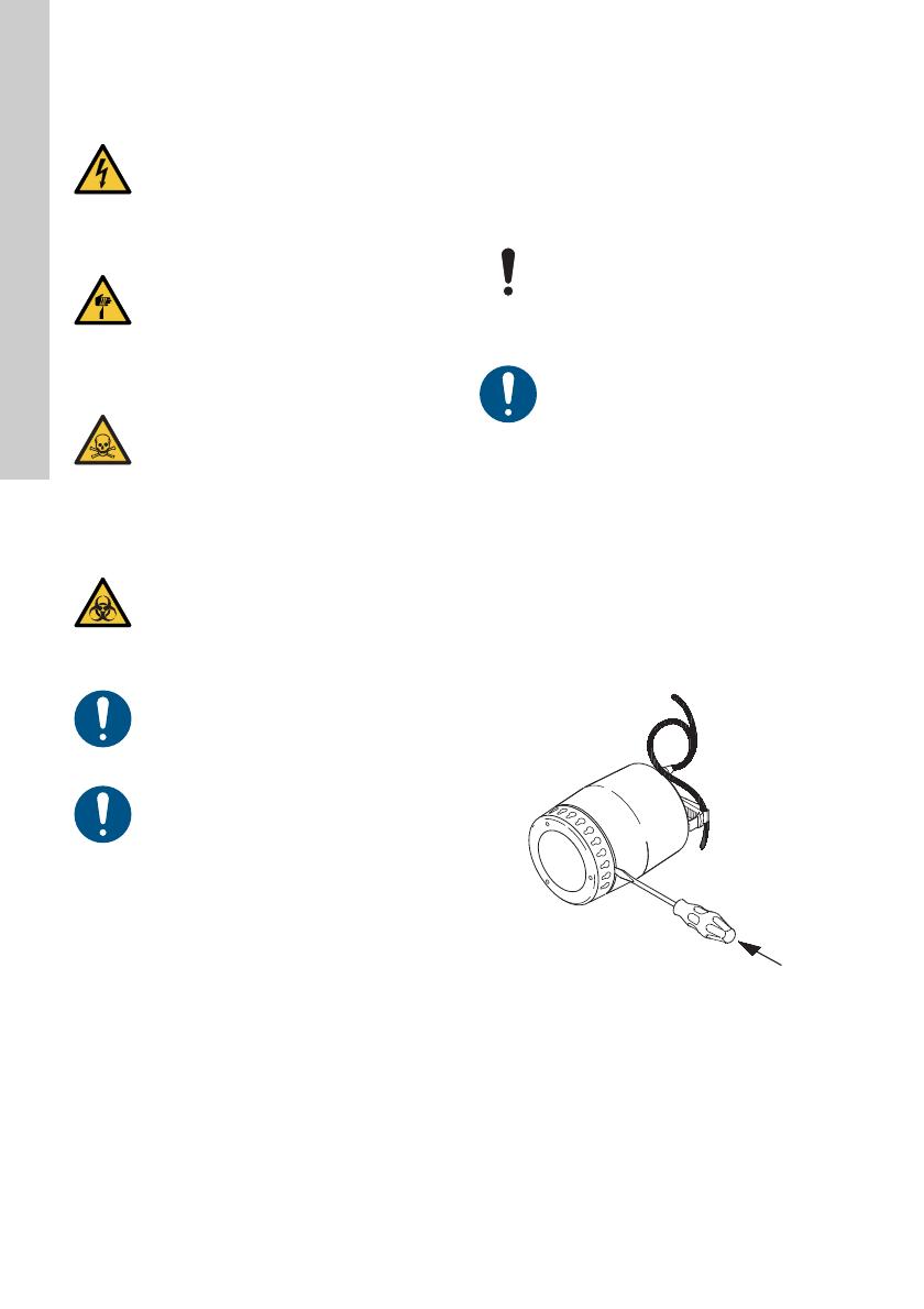
3. Carefully loosen the inlet strainer by inserting a
screwdriver in the recess between the pump
sleeve and the strainer. Use the screwdriver to
push apart the outer casing and the strainer.
Repeat the procedure, working around the pump,
until the strainer is free and can be removed. See
fig. 11.
Fig. 11 How to remove the inlet strainer
4. Remove the inlet strainer, clean and refit it.
DANGER
Electric shock
Death or serious personal injury
- Switch off the power supply before
starting any work on the product.
- Make sure that the power supply cannot
be accidentally switched on.
CAUTION
Sharp element
Minor or moderate personal injury
- Wear personal protective equipment.
CAUTION
Toxic material
Minor or moderate personal injury
- The product will be classified as
contaminated if it has been used for a
liquid which is injurious to health or
toxic.
- Wear personal protective equipment.
CAUTION
Biological hazard
Minor or moderate personal injury
- Flush the product thoroughly with clean
water and rinse the parts in water after
dismantling.
- Wear personal protective equipment.
If the power cable or the level switch is
damaged, it must be replaced by a service
workshop authorised by Grundfos.
Service must be carried out by specially
trained persons.
Furthermore, all rules and regulations
covering safety, health and environment
must be observed.
The pump contains approx. 70 ml of non-
toxic motor liquid which will be mixed with
the pumped liquid in case of a leak.
The inlet strainer and the pump housing
can be dismantled by untrained persons.
Further disassembly of the pump must be
carried out by a specially trained person.
TM03 1167 1205
English (GB)
11
6.2.2 Cleaning the inside of the pump
If the pump still delivers too little water, dismantle the
pump further.
1. Disconnect the power supply.
2. Remove the inlet strainer. See point 3 above.
3. Turn the pump housing 90 ° counterclockwise
using a screwdriver. See the arrow on the pump
housing.
4. Pull off the pump housing. See fig. 12.
Fig. 12 How to remove the pump housing
5. Clean and flush the inside of the pump to remove
possible impurities between the motor and pump
sleeve.
6. Clean the impeller. See fig. 13.
Fig. 13 How to flush the impeller
7. Check that the impeller can rotate freely. If not,
remove the impeller as described below.
8. Unscrew the nut, cross width 13 mm, from the
motor shaft. Use a screwdriver to prevent the
impeller from rotating. See fig. 14.
Fig. 14 How to remove the impeller
9. Clean the impeller and the area around the shaft.
10. Check the impeller, the pump housing and the
sealing part. If necessary, replace defective
parts.
6.2.3 Assembling the pump
Assemble the pump in the reverse order of
dismantling.
Before and during the mounting of the
pump housing, check that the sealing part
is fitted correctly. See fig. 15.
Moisten the sealing part with water to ease
the fitting.
TM03 1168 1205TM03 1169 1205
Pump housing
TM03 1170 1205
Further disassembly of the pump must be
carried out by a specially trained person.
English (GB)
12
6.3 Service kits
The impeller, the inlet strainer and the non-return
valve are replaceable.
Order numbers for the ordering of service kits and
contents of service kits appear from the tables below
and fig. 15.
Fig. 15 Service parts
If other pump components are damaged or defective,
contact the pump supplier.
6.4 Contaminated pumps
The product will be classified as contaminated if it
has been used for a liquid which is injurious to health
or toxic.
If you request Grundfos to service the product,
contact Grundfos with details about the pumped
liquid before returning the product for service.
Otherwise, Grundfos can refuse to accept the
product for service.
Any application for service must include details
about the pumped liquid.
Clean the product in the best possible way before
you return it.
Costs of returning the product are to be paid by the
customer.
Pump type Part number
Impeller kit
Unilift KP 150
Unilift KP 250
Unilift KP 350
015778
015779
015787
Inlet strainer
Unilift KP 150
Unilift KP 250
96548064
Unilift KP 350 96548066
Non-return valve
Unilift KP 150
Unilift KP 250
Unilift KP 350
15220
Service kits Pos. Designation Quantity
Impeller kit
A Impeller 1
BNut 1
C Sealing part 1
Inlet strainer D Inlet strainer 1
TM03 1166 1205
D
C
B
A
If the power cable or the level switch is
damaged, it must be replaced by a service
workshop authorised by Grundfos.
CAUTION
Biological hazard
Minor or moderate personal injury
- Flush the product thoroughly with clean
water and rinse the parts in water after
dismantling.
- Wear personal protective equipment.
English (GB)
13
7. Fault finding the product
DANGER
Electric shock
Death or serious personal injury
- Before starting any work on the product,
make sure that the power supply has
been switched off and that it cannot be
accidentally switched on.
CAUTION
Sharp element
Minor or moderate personal injury
- Wear personal protective equipment.
CAUTION
Toxic material
Minor or moderate personal injury
- The product will be classified as
contaminated if it has been used for a
liquid which is injurious to health or
toxic.
- Wear personal protective equipment.
Fault Cause Remedy
1. The motor does not
start.
a) No power supply. Connect the power supply.
b) The pump was stopped by the
level switch.
Unilift KP-A: Adjust or replace the level
switch.
c) The fuses have blown. Replace the fuses.
d) The motor protection or thermal
relay has tripped.
Wait until the motor protection trips in
again or reset the relay.
e) The impeller is blocked by
impurities.
Clean the impeller.
f) Short circuit in the cable or motor. Replace the defective part.
2. The motor protection
or thermal relay trips
after a short time of
operation.
a) The liquid temperature is too high. The pump starts automatically after
sufficient cooling. If not, use another
pump type. Contact your local
Grundfos supplier or sales support.
b) The impeller is blocked or partly
blocked by impurities.
Clean the pump.
c) Phase failure. Call an electrician.
d) Too low voltage. Call an electrician.
e) The overload setting of the motor-
protective circuit breaker is too
low.
Adjust the setting.
3. The pump runs
constantly or gives
too little water.
a) The pump is partly blocked by
impurities.
Clean the pump.
b) The outlet pipe or valve is partly
blocked by impurities.
Clean the outlet pipe or valve.
c) The impeller is not properly fixed
to the shaft.
Tighten the impeller.
d) Incorrect direction of rotation. See
section 3.3.1 Checking the
direction of rotation.
Reverse the direction of rotation.
e) Incorrect setting of the level
switch.
Adjust the level switch.
f) The pump is too small for the
application.
Replace the pump.
g) The impeller is worn. Replace the impeller.
English (GB)
14
4. The pump runs but
gives no water.
a) The pump is blocked by
impurities.
Clean the pump.
b) The outlet pipe or valve is blocked
by impurities.
Clean the outlet pipe or valve.
c) The impeller is not properly fixed
to the shaft.
Tighten the impeller.
d) There is air in the pump. Vent the pump and the outlet pipe.
e) The liquid level is too low. The
pump inlet is not completely
submerged in the pumped liquid.
Submerge the pump in the liquid or
adjust the level switch.
f) Pumps with float switch: The float
switch does not move freely.
Adjust the float switch. See section
3.2.5 Start and stop levels.
Fault Cause Remedy
English (GB)
15
8. Technical data
8.1 Storage temperature
-20 - +70 °C.
8.2 Operating conditions
8.2.1 Liquid temperature
Minimum 0 °C.
The maximum liquid temperature depends on the
rated voltage of the pump. See the table below.
1)
Voltage variant for Unilift KP 350.
2)
KP 350: 45.
8.3 Sound pressure level
The sound pressure level of the pump is lower than
the limiting values stated in the EC Council Directive
2006/42/EC relating to machinery.
9. Disposing of the product
This product or parts of it must be disposed of in an
environmentally sound way:
1. Use the public or private waste collection service.
2. If this is not possible, contact the nearest
Grundfos company or service workshop.
The crossed-out wheelie bin symbol on
a product means that it must be
disposed of separately from household
waste. When a product marked with this
symbol reaches its end of life, take it to a
collection point designated by the local
waste disposal authorities. The separate collection
and recycling of such products will help protect the
environment and human health.
See also end-of-life information at
www.grundfos.com/product-recycling.
Installation depth
Maximum 10 m below liquid
level
pH value 4-10
Density Maximum 1100 kg/m
3
Viscosity Maximum 1 mm
2
/s
Maximum particle
size
Max. spherical diameter:
10 mm
Technical data See the pump nameplate.
Make sure that there are minimum 3 m
free cable above the liquid level. This limits
the maximum installation depth to 7 m for
pumps with 10 m cable and to 2 m for
pumps with 5 m cable.
Voltage
Maximum liquid
temperature
[°C]
1 x 100 V, 50 Hz
1 x 110 V, 50 Hz
1 x 100-110 V, 50 Hz
1)
1 x 220-230 V, 50 Hz
1 x 220-240 V, 50 Hz, 50 Hz
1)
1 x 230-240 V, 50 Hz
35
40
40
50
50
50
1 x 100 V, 60 Hz
1 x 115 V, 60 Hz
1 x 220 V, 60 Hz
35
50
2)
40
3 x 200 V, 50 Hz
3 x 380-400 V, 50 Hz
1)
3 x 380-415 V, 50 Hz
35
50
50
3 x 200 V, 60 Hz 35
At intervals of at least 30 minutes, the pumps may,
however, run at maximum 70 °C for periods not
exceeding 2 minutes.
Appendix
16
Appendix 1
Dimensions
Unilift KP-AV Unilift KP-M
* Unilift KP 350
TM01 1523 4502
TM00 1642 1093
31
149
236
214
140
215
Rp 1 1/4
148
30
220 (230*)
256 (266*)
148
30
140
Rp 1
220
226
1
4
226 (236*)
220 (230*)
1 1/4
17
Grundfos companies
Argentina
Bombas GRUNDFOS de Argentina S.A.
Ruta Panamericana km. 37.500 Centro
Industrial Garin
1619 Garín Pcia. de B.A.
Phone: +54-3327 414 444
Telefax: +54-3327 45 3190
Australia
GRUNDFOS Pumps Pty. Ltd.
P.O. Box 2040
Regency Park
South Australia 5942
Phone: +61-8-8461-4611
Telefax: +61-8-8340 0155
Austria
GRUNDFOS Pumpen Vertrieb
Ges.m.b.H.
Grundfosstraße 2
A-5082 Grödig/Salzburg
Tel.: +43-6246-883-0
Telefax: +43-6246-883-30
Belgium
N.V. GRUNDFOS Bellux S.A.
Boomsesteenweg 81-83
B-2630 Aartselaar
Tél.: +32-3-870 7300
Télécopie: +32-3-870 7301
Belarus
Представительство ГРУНДФОС в
Минске
220125, Минск
ул. Шафарнянская, 11, оф. 56, БЦ
«Порт»
Тел.: +7 (375 17) 286 39 72/73
Факс: +7 (375 17) 286 39 71
Bosnia and Herzegovina
GRUNDFOS Sarajevo
Zmaja od Bosne 7-7A,
BH-71000 Sarajevo
Phone: +387 33 592 480
Telefax: +387 33 590 465
www.ba.grundfos.com
e-mail: grun[email protected]et.ba
Brazil
BOMBAS GRUNDFOS DO BRASIL
Av. Humberto de Alencar Castelo
Branco, 630
CEP 09850 - 300
São Bernardo do Campo - SP
Phone: +55-11 4393 5533
Telefax: +55-11 4343 5015
Bulgaria
Grundfos Bulgaria EOOD
Slatina District
Iztochna Tangenta street no. 100
BG - 1592 Sofia
Tel. +359 2 49 22 200
Fax. +359 2 49 22 201
email: bulgari[email protected]
Canada
GRUNDFOS Canada Inc.
2941 Brighton Road
Oakville, Ontario
L6H 6C9
Phone: +1-905 829 9533
Telefax: +1-905 829 9512
China
GRUNDFOS Pumps (Shanghai) Co. Ltd.
10F The Hub, No. 33 Suhong Road
Minhang District
Shanghai 201106
PRC
Phone: +86 21 612 252 22
Telefax: +86 21 612 253 33
COLOMBIA
GRUNDFOS Colombia S.A.S.
Km 1.5 vía Siberia-Cota Conj. Potrero
Chico,
Parque Empresarial Arcos de Cota Bod.
1A.
Cota, Cundinamarca
Phone: +57(1)-2913444
Telefax: +57(1)-8764586
Croatia
GRUNDFOS CROATIA d.o.o.
Buzinski prilaz 38, Buzin
HR-10010 Zagreb
Phone: +385 1 6595 400
Telefax: +385 1 6595 499
www.hr.grundfos.com
GRUNDFOS Sales Czechia and
Slovakia s.r.o.
Čajkovského 21
779 00 Olomouc
Phone: +420-585-716 111
Denmark
GRUNDFOS DK A/S
Martin Bachs Vej 3
DK-8850 Bjerringbro
Tlf.: +45-87 50 50 50
Telefax: +45-87 50 51 51
www.grundfos.com/DK
Estonia
GRUNDFOS Pumps Eesti OÜ
Peterburi tee 92G
11415 Tallinn
Tel: + 372 606 1690
Fax: + 372 606 1691
Finland
OY GRUNDFOS Pumput AB
Trukkikuja 1
FI-01360 Vantaa
Phone: +358-(0) 207 889 500
France
Pompes GRUNDFOS Distribution S.A.
Parc d’Activités de Chesnes
57, rue de Malacombe
F-38290 St. Quentin Fallavier (Lyon)
Tél.: +33-4 74 82 15 15
Télécopie: +33-4 74 94 10 51
Germany
GRUNDFOS GMBH
Schlüterstr. 33
40699 Erkrath
Tel.: +49-(0) 211 929 69-0
Telefax: +49-(0) 211 929 69-3799
e-mail: infoservice@grundfos.de
Service in Deutschland:
e-mail: kunde[email protected]
Greece
GRUNDFOS Hellas A.E.B.E.
20th km. Athinon-Markopoulou Av.
P.O. Box 71
GR-19002 Peania
Phone: +0030-210-66 83 400
Telefax: +0030-210-66 46 273
Hong Kong
GRUNDFOS Pumps (Hong Kong) Ltd.
Unit 1, Ground floor
Siu Wai Industrial Centre
29-33 Wing Hong Street &
68 King Lam Street, Cheung Sha Wan
Kowloon
Phone: +852-27861706 / 27861741
Telefax: +852-27858664
Hungary
GRUNDFOS Hungária Kft.
Tópark u. 8
H-2045 Törökbálint,
Phone: +36-23 511 110
Telefax: +36-23 511 111
India
GRUNDFOS Pumps India Private
Limited
118 Old Mahabalipuram Road
Thoraipakkam
Chennai 600 096
Phone: +91-44 2496 6800
Indonesia
PT. GRUNDFOS POMPA
Graha Intirub Lt. 2 & 3
Jln. Cililitan Besar No.454. Makasar,
Jakarta Timur
ID-Jakarta 13650
Phone: +62 21-469-51900
Telefax: +62 21-460 6910 / 460 6901
Ireland
GRUNDFOS (Ireland) Ltd.
Unit A, Merrywell Business Park
Ballymount Road Lower
Dublin 12
Phone: +353-1-4089 800
Telefax: +353-1-4089 830
Italy
GRUNDFOS Pompe Italia S.r.l.
Via Gran Sasso 4
I-20060 Truccazzano (Milano)
Tel.: +39-02-95838112
Telefax: +39-02-95309290 / 95838461
Japan
GRUNDFOS Pumps K.K.
1-2-3, Shin-Miyakoda, Kita-ku,
Hamamatsu
431-2103 Japan
Phone: +81 53 428 4760
Telefax: +81 53 428 5005
Korea
GRUNDFOS Pumps Korea Ltd.
6th Floor, Aju Building 679-5
Yeoksam-dong, Kangnam-ku, 135-916
Seoul, Korea
Phone: +82-2-5317 600
Telefax: +82-2-5633 725
Latvia
SIA GRUNDFOS Pumps Latvia
Deglava biznesa centrs
Augusta Deglava ielā 60, LV-1035, Rīga,
Tālr.: + 371 714 9640, 7 149 641
Fakss: + 371 914 9646
Lithuania
GRUNDFOS Pumps UAB
Smolensko g. 6
LT-03201 Vilnius
Tel: + 370 52 395 430
Fax: + 370 52 395 431
Grundfos companies
Malaysia
GRUNDFOS Pumps Sdn. Bhd.
7 Jalan Peguam U1/25
Glenmarie Industrial Park
40150 Shah Alam
Selangor
Phone: +60-3-5569 2922
Telefax: +60-3-5569 2866
Mexico
Bombas GRUNDFOS de México S.A. de
C.V.
Boulevard TLC No. 15
Parque Industrial Stiva Aeropuerto
Apodaca, N.L. 66600
Phone: +52-81-8144 4000
Telefax: +52-81-8144 4010
Netherlands
GRUNDFOS Netherlands
Veluwezoom 35
1326 AE Almere
Postbus 22015
1302 CA ALMERE
Tel.: +31-88-478 6336
Telefax: +31-88-478 6332
E-mail: info_gnl@grundfos.com
New Zealand
GRUNDFOS Pumps NZ Ltd.
17 Beatrice Tinsley Crescent
North Harbour Industrial Estate
Albany, Auckland
Phone: +64-9-415 3240
Telefax: +64-9-415 3250
Norway
GRUNDFOS Pumper A/S
Strømsveien 344
Postboks 235, Leirdal
N-1011 Oslo
Tlf.: +47-22 90 47 00
Telefax: +47-22 32 21 50
Poland
GRUNDFOS Pompy Sp. z o.o.
ul. Klonowa 23
Baranowo k. Poznania
PL-62-081 Przeźmierowo
Tel: (+48-61) 650 13 00
Fax: (+48-61) 650 13 50
Portugal
Bombas GRUNDFOS Portugal, S.A.
Rua Calvet de Magalhães, 241
Apartado 1079
P-2770-153 Paço de Arcos
Tel.: +351-21-440 76 00
Telefax: +351-21-440 76 90
Romania
GRUNDFOS Pompe România SRL
Bd. Biruintei, nr 103
Pantelimon county Ilfov
Phone: +40 21 200 4100
Telefax: +40 21 200 4101
E-mail: romani[email protected]
Russia
ООО Грундфос Россия
ул. Школьная, 39-41
Москва, RU-109544, Russia
Тел. (+7) 495 564-88-00 (495) 737-30-
00
Факс (+7) 495 564 8811
E-mail grundfos.moscow@grundfos.com
Serbia
Grundfos Srbija d.o.o.
Omladinskih brigada 90b
11070 Novi Beograd
Phone: +381 11 2258 740
Telefax: +381 11 2281 769
www.rs.grundfos.com
Singapore
GRUNDFOS (Singapore) Pte. Ltd.
25 Jalan Tukang
Singapore 619264
Phone: +65-6681 9688
Telefax: +65-6681 9689
Slovakia
GRUNDFOS s.r.o.
Prievozská 4D
821 09 BRATISLAVA
Phona: +421 2 5020 1426
sk.grundfos.com
Slovenia
GRUNDFOS LJUBLJANA, d.o.o.
Leskoškova 9e, 1122 Ljubljana
Phone: +386 (0) 1 568 06 10
Telefax: +386 (0)1 568 06 19
South Africa
Grundfos (PTY) Ltd.
16 Lascelles Drive, Meadowbrook Estate
1609 Germiston, Johannesburg
Tel.: (+27) 10 248 6000
Fax: (+27) 10 248 6002
E-mail: lgrad[email protected]
Spain
Bombas GRUNDFOS España S.A.
Camino de la Fuentecilla, s/n
E-28110 Algete (Madrid)
Tel.: +34-91-848 8800
Telefax: +34-91-628 0465
Sweden
GRUNDFOS AB
Box 333 (Lunnagårdsgatan 6)
431 24 Mölndal
Tel.: +46 31 332 23 000
Telefax: +46 31 331 94 60
Switzerland
GRUNDFOS Pumpen AG
Bruggacherstrasse 10
CH-8117 Fällanden/ZH
Tel.: +41-44-806 8111
Telefax: +41-44-806 8115
Taiwan
GRUNDFOS Pumps (Taiwan) Ltd.
7 Floor, 219 Min-Chuan Road
Taichung, Taiwan, R.O.C.
Phone: +886-4-2305 0868
Telefax: +886-4-2305 0878
Thailand
GRUNDFOS (Thailand) Ltd.
92 Chaloem Phrakiat Rama 9 Road,
Dokmai, Pravej, Bangkok 10250
Phone: +66-2-725 8999
Telefax: +66-2-725 8998
Turkey
GRUNDFOS POMPA San. ve Tic. Ltd.
Sti.
Gebze Organize Sanayi Bölgesi
Ihsan dede Caddesi,
2. yol 200. Sokak No. 204
41490 Gebze/ Kocaeli
Phone: +90 - 262-679 7979
Telefax: +90 - 262-679 7905
E-mail: satis@grundfos.com
Ukraine
Бізнес Центр Європа
Столичне шосе, 103
м. Київ, 03131, Україна
Телефон: (+38 044) 237 04 00
Факс.: (+38 044) 237 04 01
E-mail: ukraine@grundfos.com
United Arab Emirates
GRUNDFOS Gulf Distribution
P.O. Box 16768
Jebel Ali Free Zone
Dubai
Phone: +971 4 8815 166
Telefax: +971 4 8815 136
United Kingdom
GRUNDFOS Pumps Ltd.
Grovebury Road
Leighton Buzzard/Beds. LU7 4TL
Phone: +44-1525-850000
Telefax: +44-1525-850011
U.S.A.
GRUNDFOS Pumps Corporation
9300 Loiret Blvd.
Lenexa, Kansas 66219
Phone: +1-913-227-3400
Telefax: +1-913-227-3500
Uzbekistan
Grundfos Tashkent, Uzbekistan The
Representative Office of Grundfos
Kazakhstan in Uzbekistan
38a, Oybek street, Tashkent
Телефон: (+998) 71 150 3290 / 71 150
3291
Факс: (+998) 71 150 3292
Addresses Revised 15.01.2019
www.grundfos.com
96894217 0819
ECM: 1260503
Trademarks displayed in this material, including but not limited to Grundfos, the Grundfos logo and “be
think innovate” are registered trademarks owned by The Grundfos Group. All rights reserved.
© 2019 Grundfos Holding A/S, all rights reserved.
  • Page 1 1
  • Page 2 2
  • Page 3 3
  • Page 4 4
  • Page 5 5
  • Page 6 6
  • Page 7 7
  • Page 8 8
  • Page 9 9
  • Page 10 10
  • Page 11 11
  • Page 12 12
  • Page 13 13
  • Page 14 14
  • Page 15 15
  • Page 16 16
  • Page 17 17
  • Page 18 18
  • Page 19 19
  • Page 20 20

Grundfos Unilift KP 150 Installation And Operating Instructions Manual

Type
Installation And Operating Instructions Manual
This manual is also suitable for

Ask a question and I''ll find the answer in the document

Finding information in a document is now easier with AI